Embracing the Broken Courtyard

GROUNDS: Generative Prototypes
NEGOTIATED
ARCH7081 Design 11 / MArch Studio Semester 1 2021-2022 Joshua Bolchover + Kent Mundle / Donn Holohan + Jersey Poon The University of Hong Kong / Department of Architecture WU Changrong 3035894216
Embracing the Broken Courtyard
MASS SUSPENDED BY THESE FRAMES THAT EMBRACE AND SUPPORT THE EXISTING BUILDINGS AND BROKEN COURTYARD.

PHASE 1: SPATIAL GENERATOR PHASE 2: SITUATING + ADAPTING PHASE 3:
Content
TRANSFORMATION 04 30 50
4
TRANSFORMATION PHASE 1:
5
1
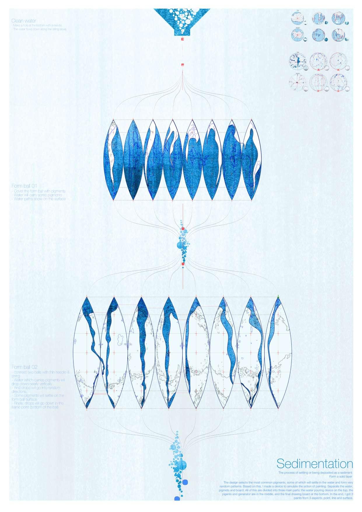
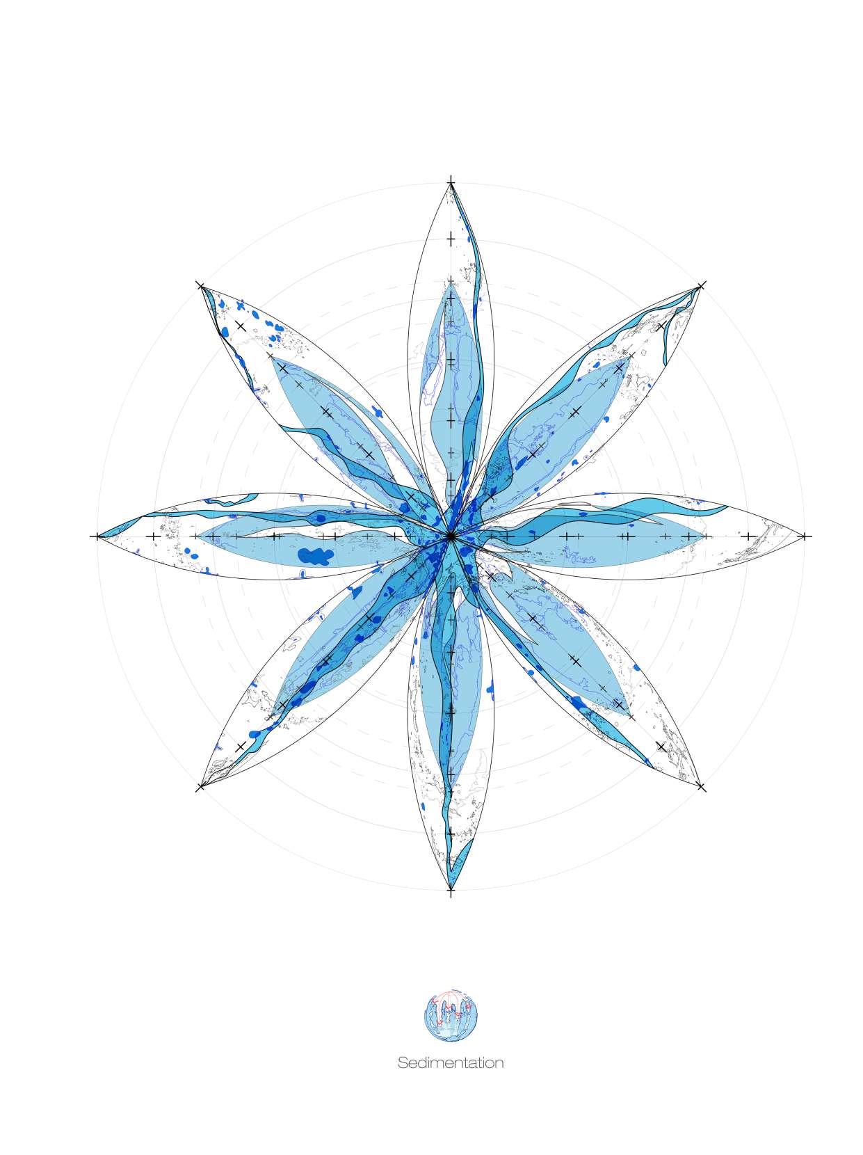
Sedimentation DEVICES AND PROCESS 01
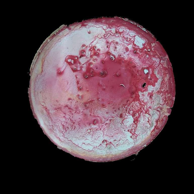
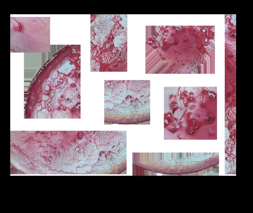
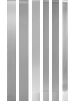
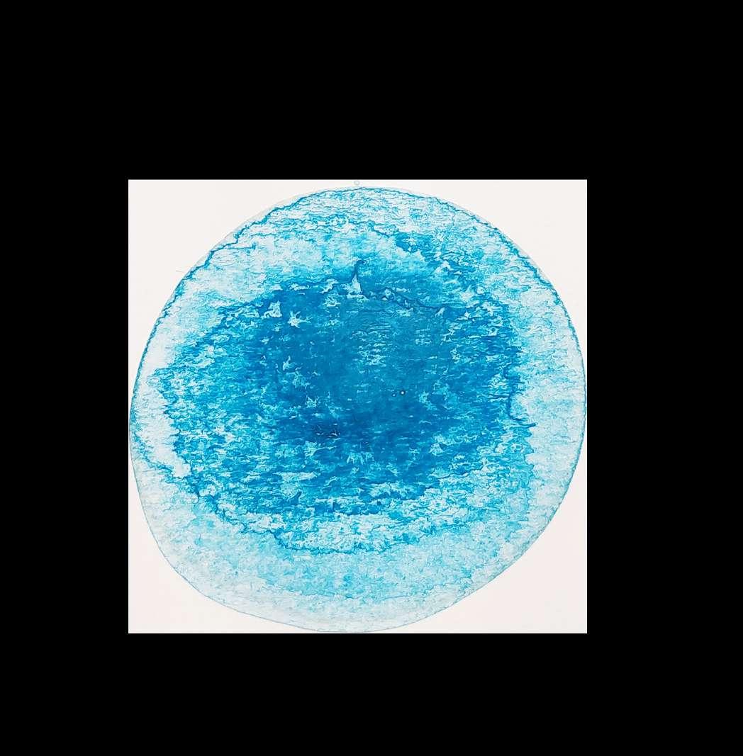
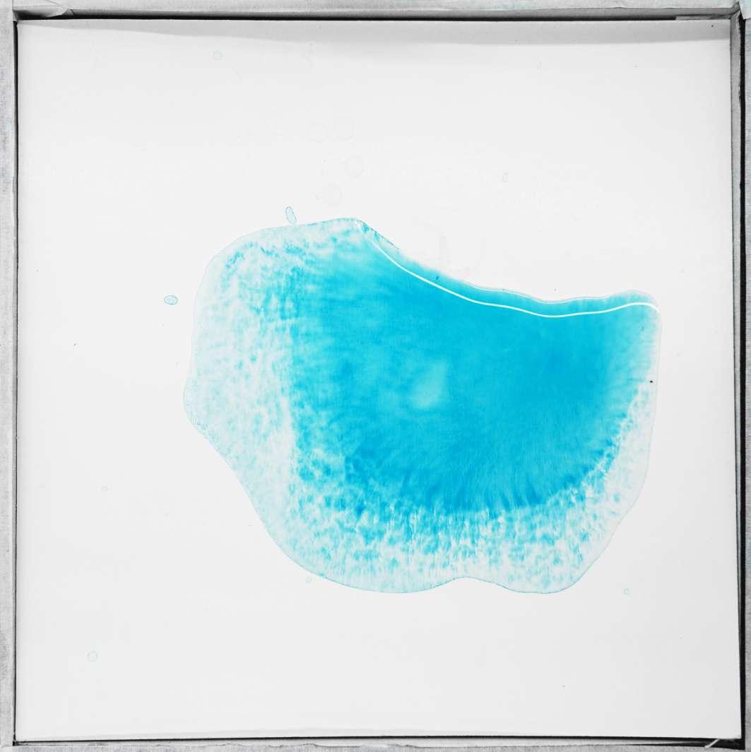
RANDOM PATTERNS
Random patterns created by pigments are pretty abstract. The random patterns produced by paint are fascinating, and you can find random forms and images from them. I mix the pigments and water and then,keep it for about 30 minutes, and finally pour out the upper layer of water,and the rest water will evaporate over time. Finally, a random pattern can be obtained. I like these patterns because you can always find some inspirations from them.
6 Phase - 1
Acne on the face River bed Cloud Fire Buddha statue Red sea Crater Sunset Smoke
7 Transformation: Sedimentation
Sedimentation DEVICES AND PROCESS 01
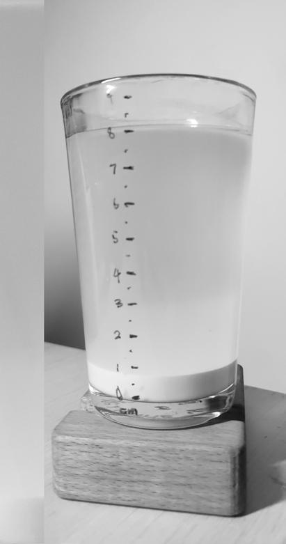
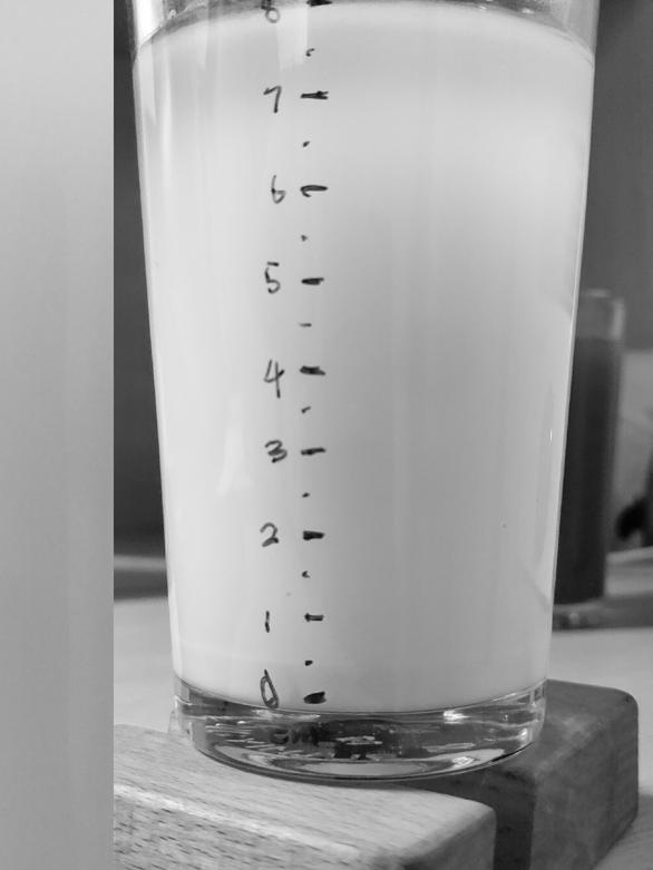
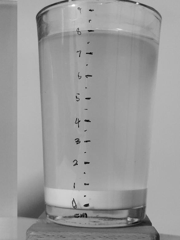
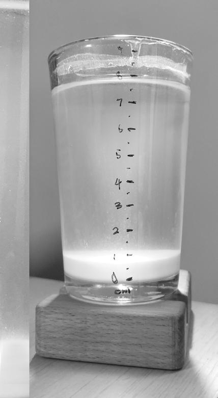
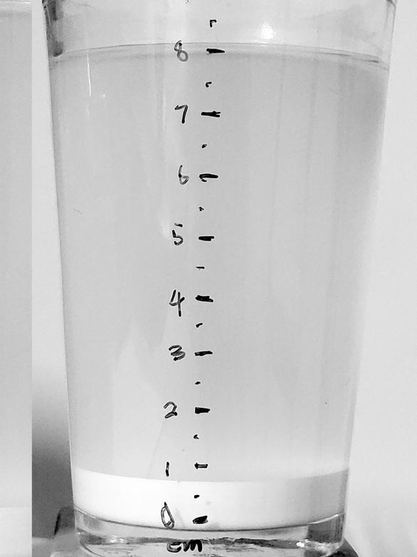
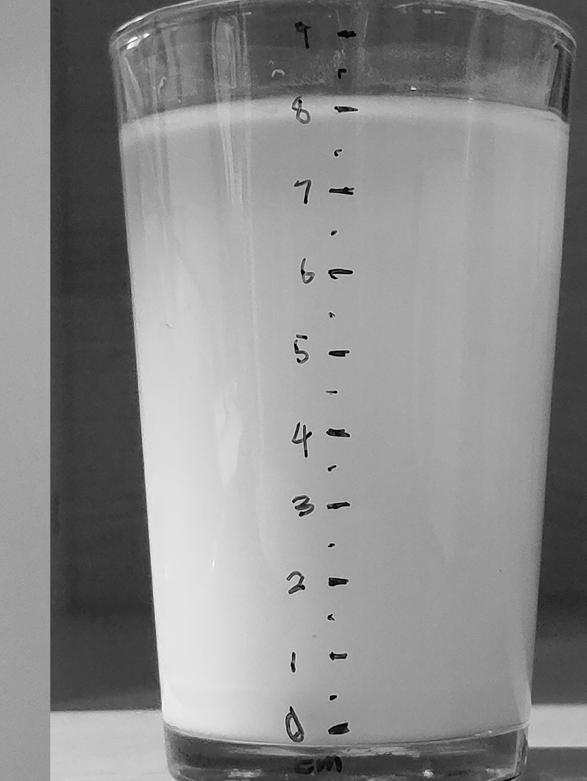
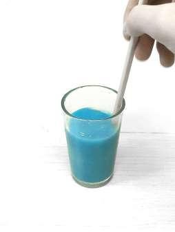
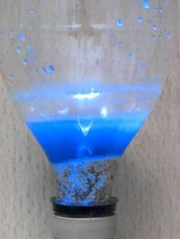
STARCH EXPERIMENT
In addition to the Sedimentation experiment on pigments, I also tried to find some particles that can observe the gradual change of the liquid, such as starch. Starch will obviously settle down and layer with moisture over time, and the water will have a gradual change from white to transparency. Maybe I can find some inspiration from it. But this is just a pure sedimentation experiment. Nothing was transformed.
8 Phase - 1
Gradient of sedimentation
9 Transformation: Sedimentation
Sedimentation
DEVICES AND PROCESS 02
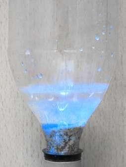
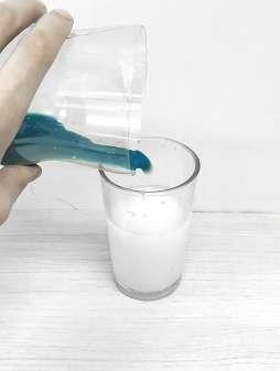
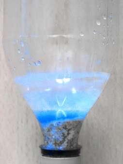
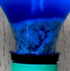
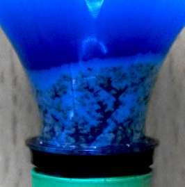
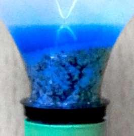
MIX EXPERIMENT
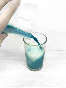
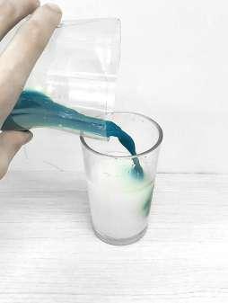
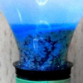
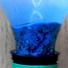
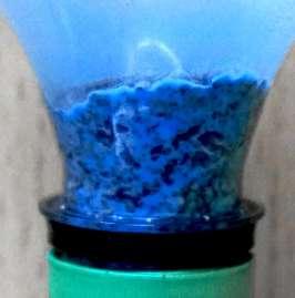
I try to do a transform experiment to record the process and pattern of sedimentation. So I decided to mix paint with starch and try to record the process. Because starch sediments more easily than pigments, starch will fill up the gaps of the stone particles (filters), so the pigments will slowly stay and the color will become lighter and lighter, and the crevices will be blocked by the starch to form a layered pattern in the filter. However, the result can not be controlled by a stable system. I need a device.
10 Phase - 1
11 Transformation: Sedimentation
Starch settles in the gaps of the stones 1. 3. 5. 2. 4. 6.
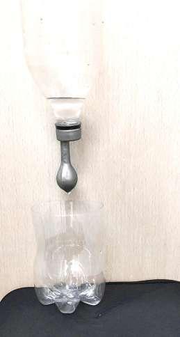
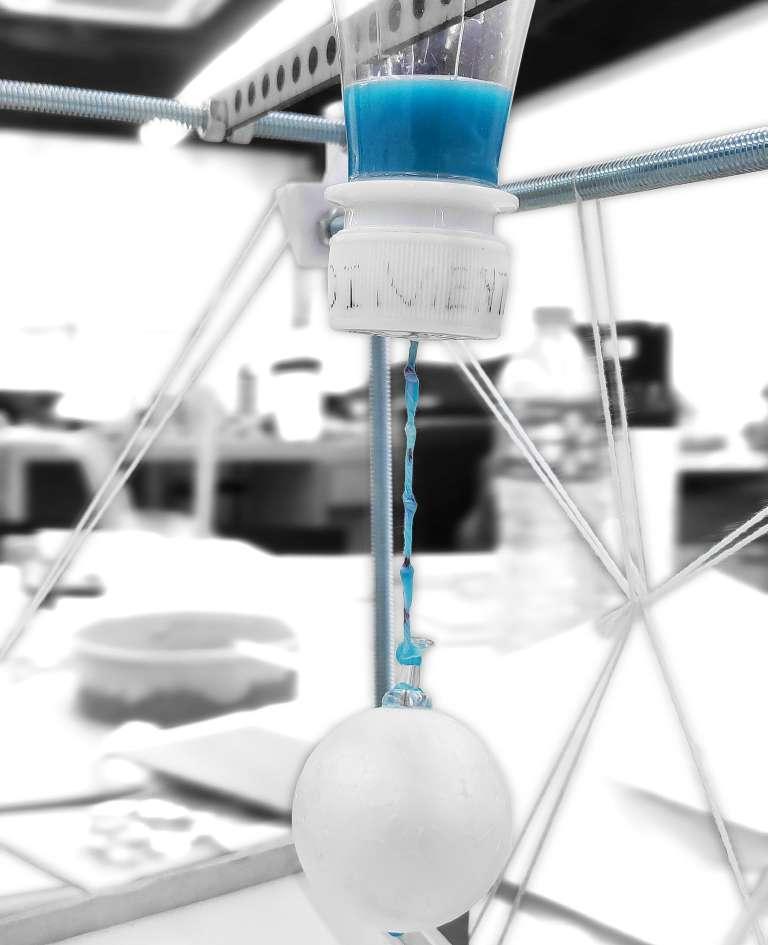
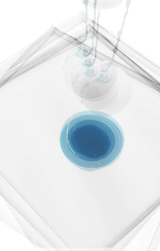
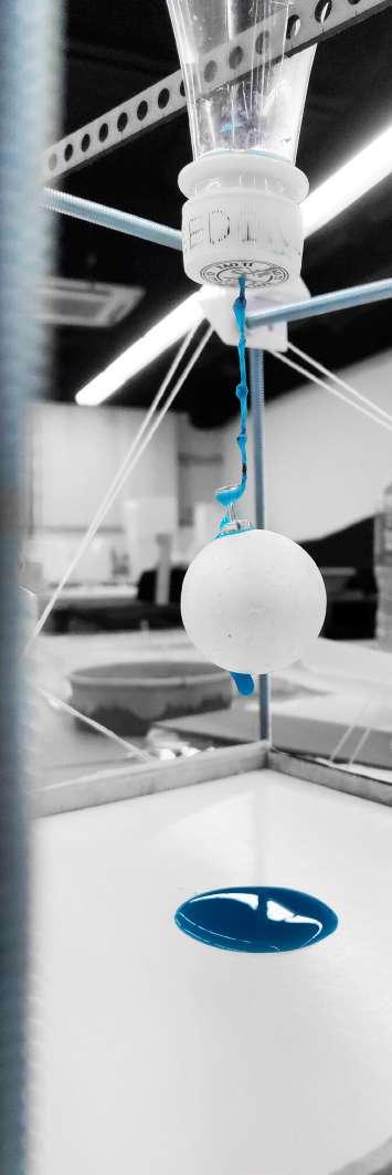
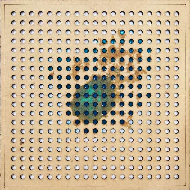
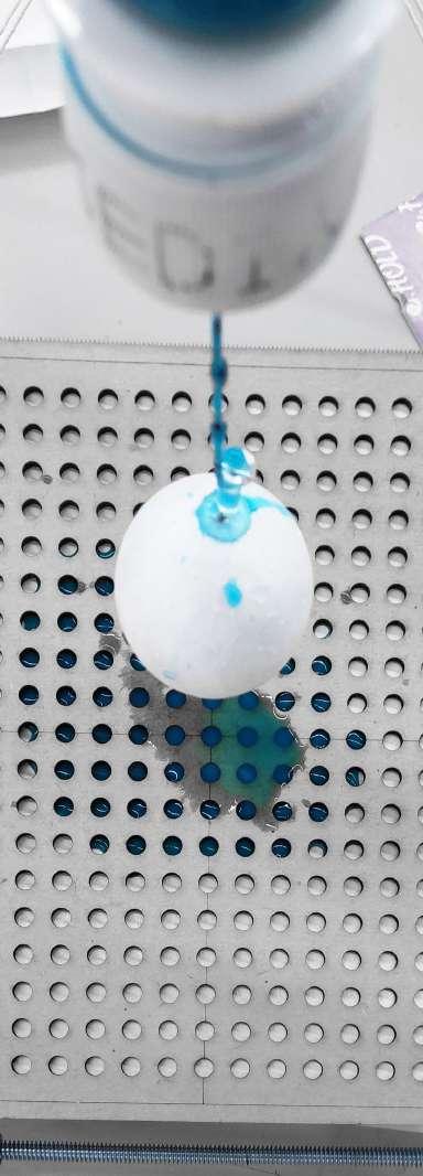
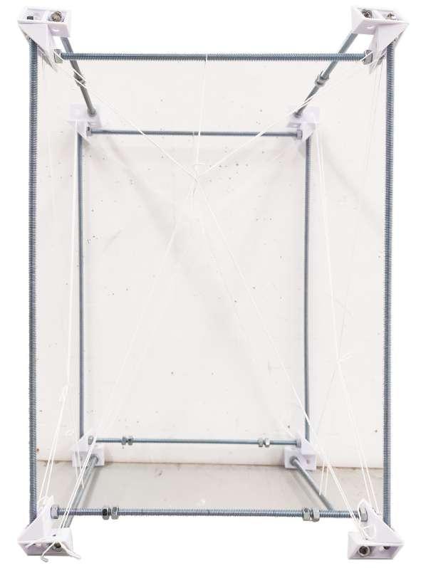
DEVICES AND PROCESS 03
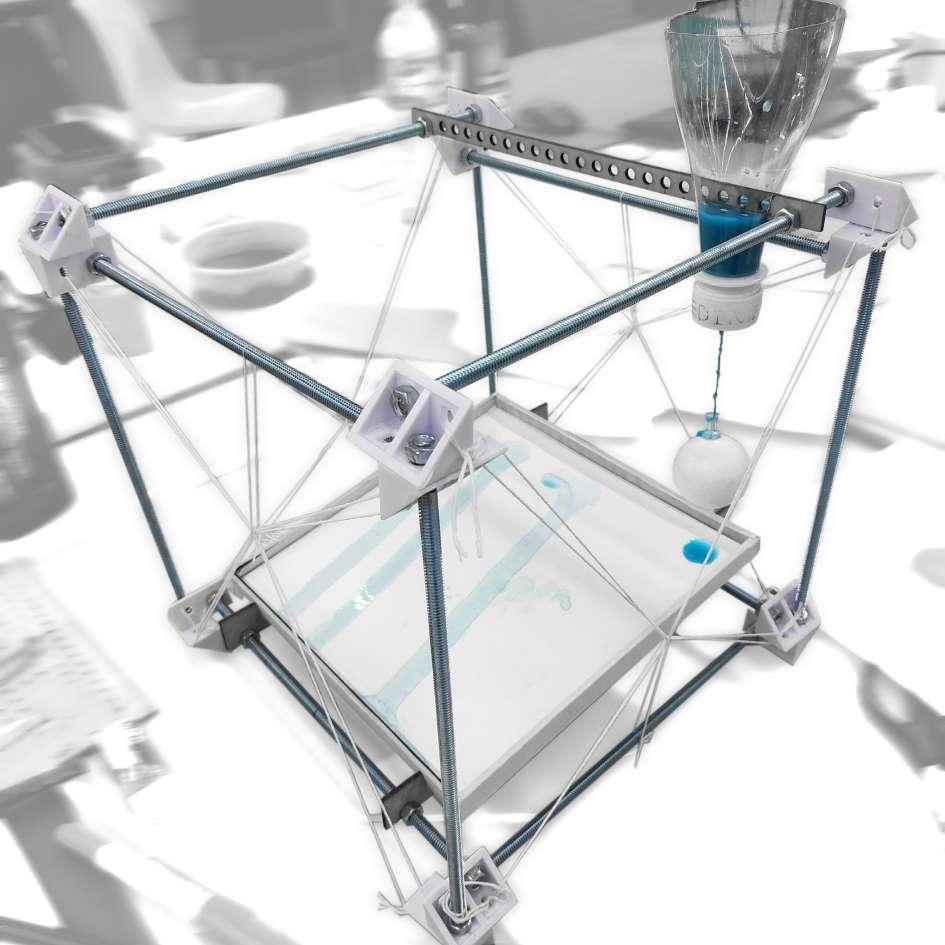
I tried to build a device to set up the various components to make the results more reliable. So I used a cube as a base frame and set up the dripper at the top, the receiver at the bottom, and the transform device in the middle. I tried to do the experiment from the three basic dimensions——point, line and Plane, and tried to use this device to replace painting brushes to see what the final result would be. In the end, I can get a very nice pattern, and the foam ball on the converter can capture some trajectories of pigments.
12 Phase - 1
DEVICE
1.0 Sedimentation
Form ball replacing the painting brushes
13 Transformation: Sedimentation
Sedimentation
DEVICES AND PROCESS 03
14 Phase - 1
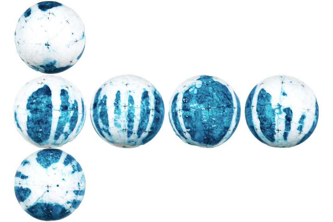
EXPERIMENT 01 (LINE)
15 Transformation: Sedimentation
LINE
Sedimentation DEVICES AND PROCESS 03
EXPERIMENT 02 (PLANE
16 Phase - 1
PLANE
17 Transformation: Sedimentation
Sedimentation DEVICES AND PROCESS 03
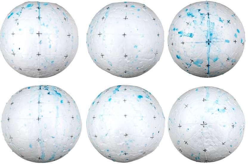
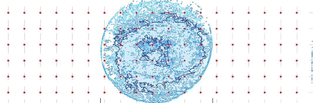
EXPERIMENT 03 (POINT)
18 Phase - 1
POINT
19 Transformation: Sedimentation
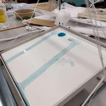
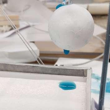
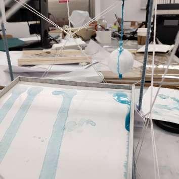
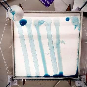
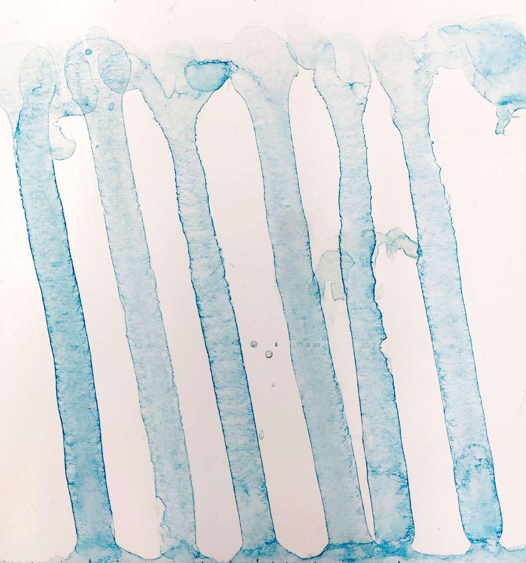
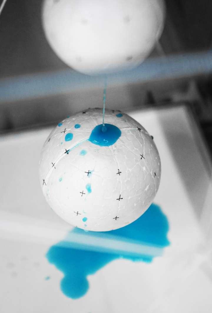
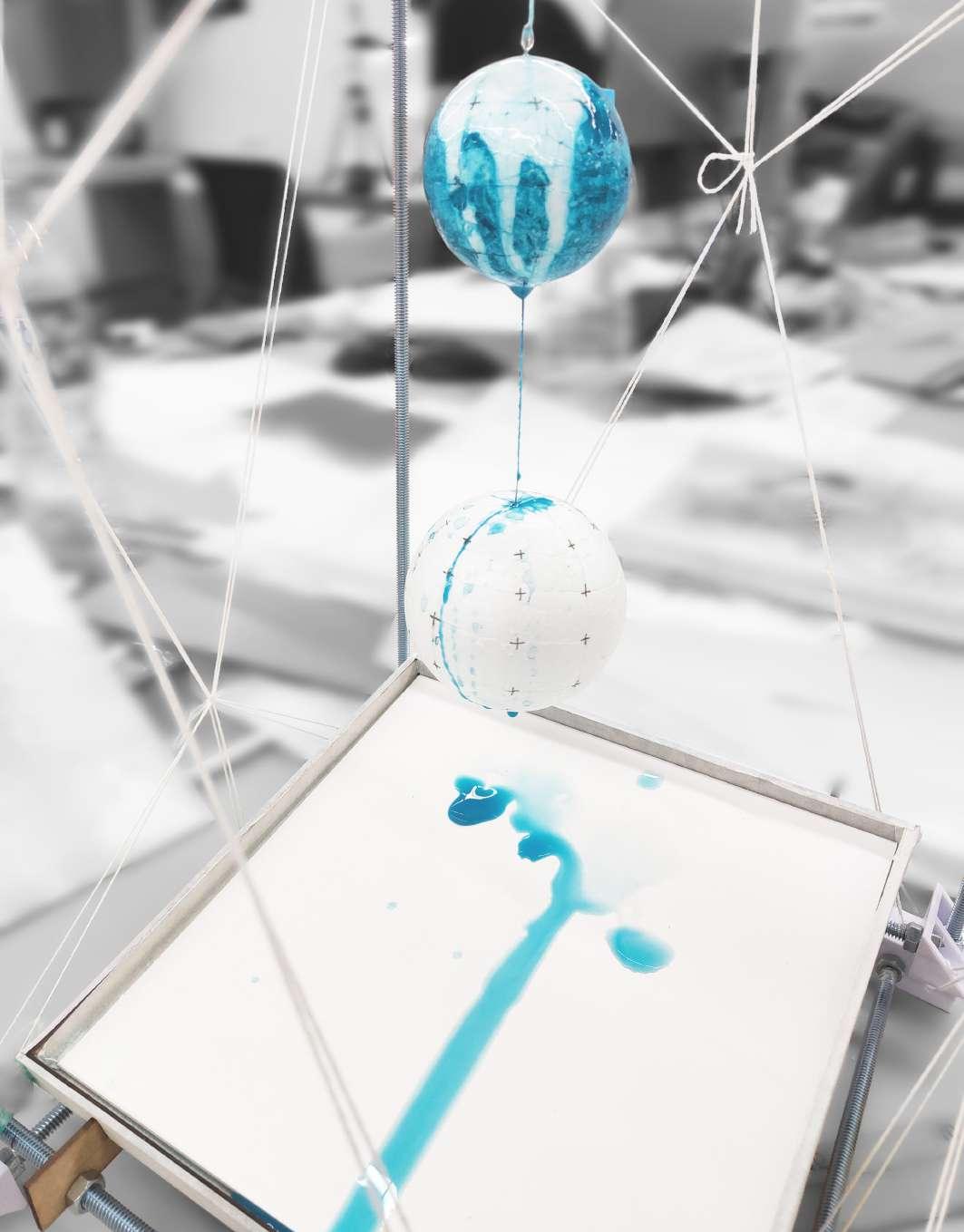
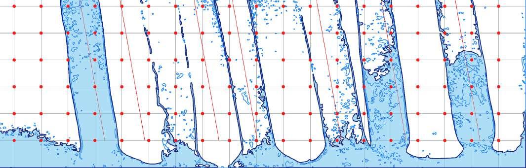
DEVICES AND PROCESS 04
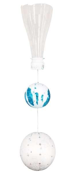
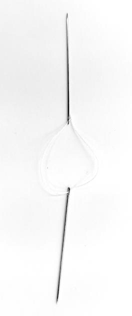
IMPROVE THE DEVICE
I should separate the pigments from the water and add a step in the middle to mix the water with the paint. In this way, only dripping water is needed, and the trajectory of the water will be captured by the first ball and form an obvious trajectory.
The middle two balls are connected with thin needles, so that it can ensure that the water can drip in the middle position and can drip randomly, and finally it can drip randomly on the drawing board.
20 Phase - 1
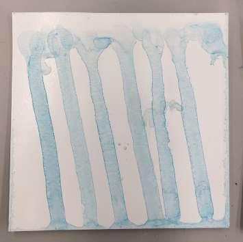
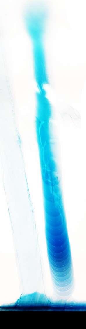
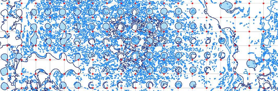
Sedimentation
PATTERNS BECOME DISORDER
21 Transformation: Sedimentation
22 Phase - 1
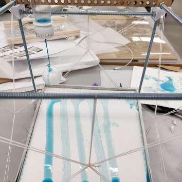
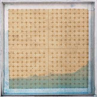
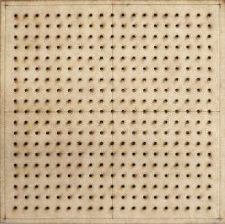
FILTER
VESSAL SUPPORT
FRAME VESSAL
NEEDLE & STRING
DROPPER & GENERATOR Sedimentation FINAL DEVICE
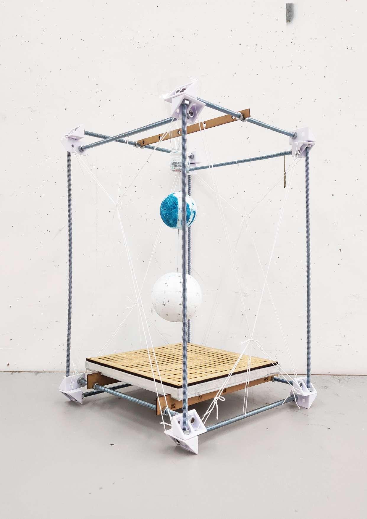
Sedimentation FINAL DEVICE
24 Phase - 1 FINAL EXPERIMENT
25 Transformation: Sedimentation
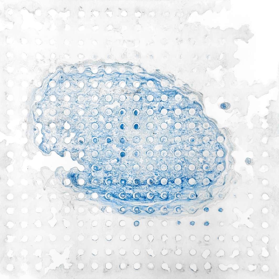
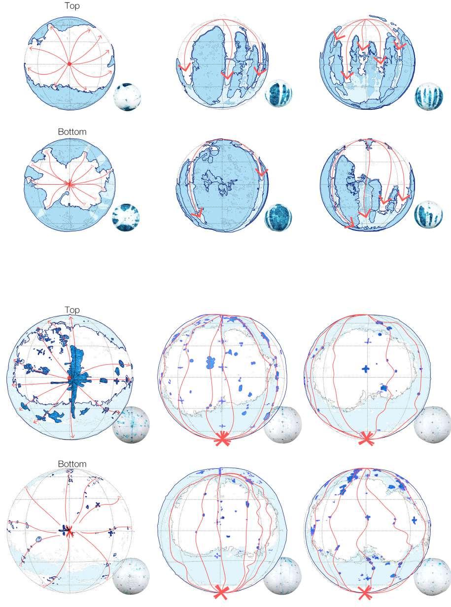
DRAWING TRANSFORMATION
FINAL PATTERNS & DIAGRAM
I try to describe the process and the result. The process is more important, because it is a process of transformation, so I will draw process and transformation by projection and overlap, to get the final pattern.
26 Phase - 1
Sedimentation
FINAL DRAWING
28 Phase - 1 Sedimentation
30
SPATIAL GENERATOR PHASE 2:
31
2
PROCESS 01
FREE FORM - to active the site ground
I try to describe the process and the result. The process is more important, because it is a process of transformation, so I will draw process and transformation by projection and overlap, to get the final pattern.
32 Phase - 2
Start from Free Form
Free Form As a Spatial Generator
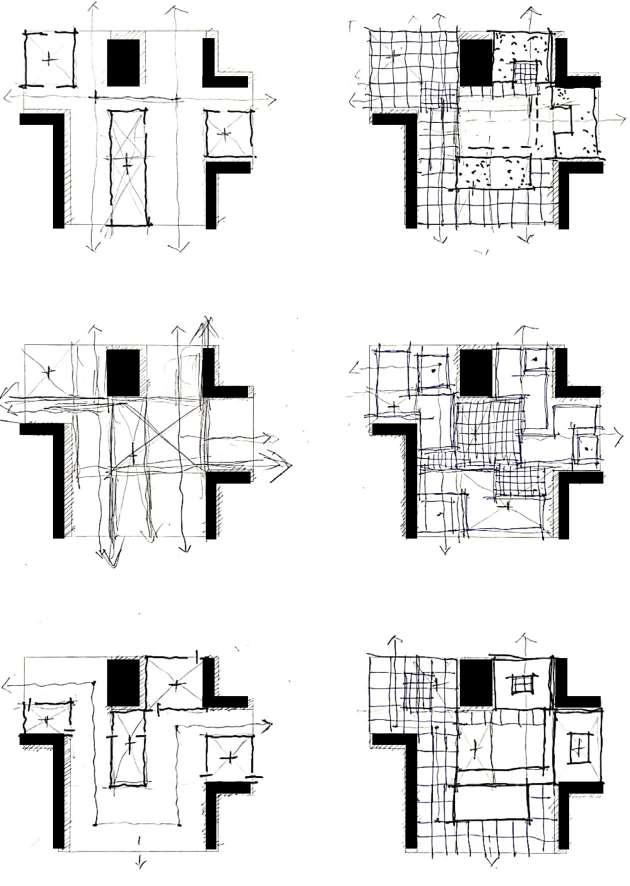
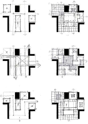
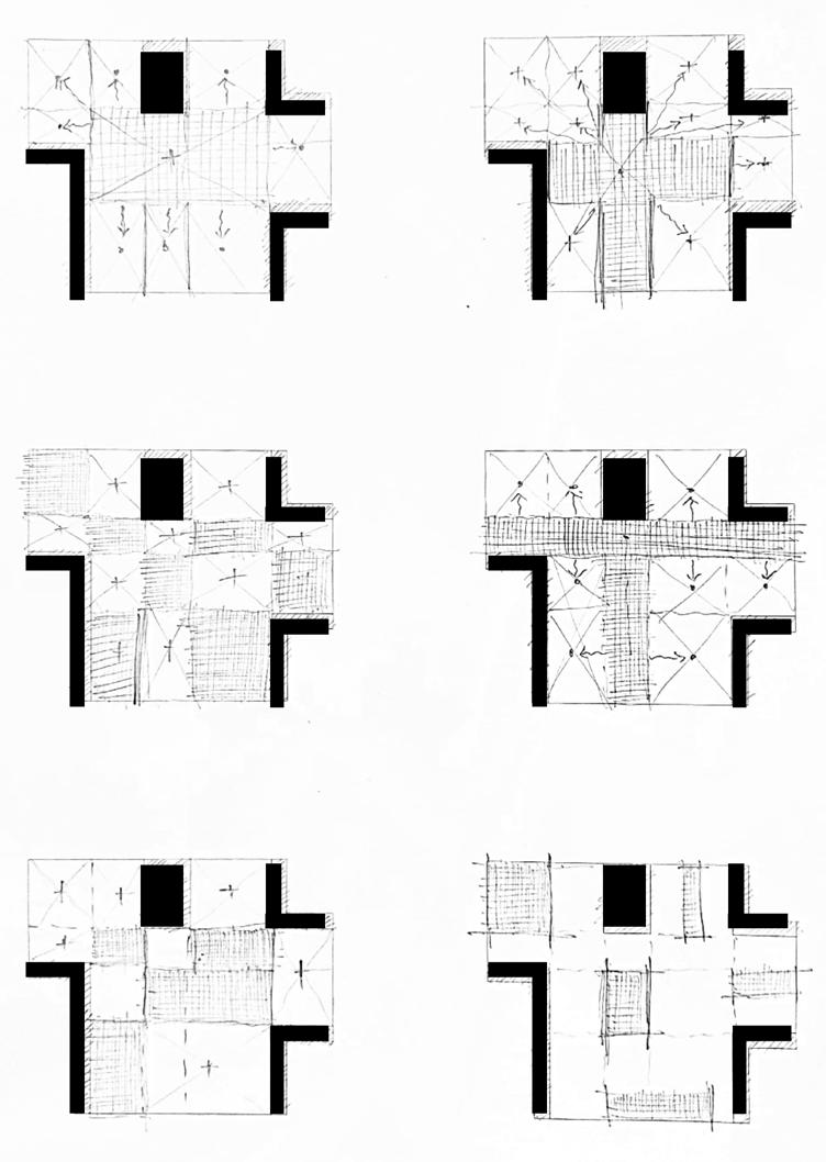
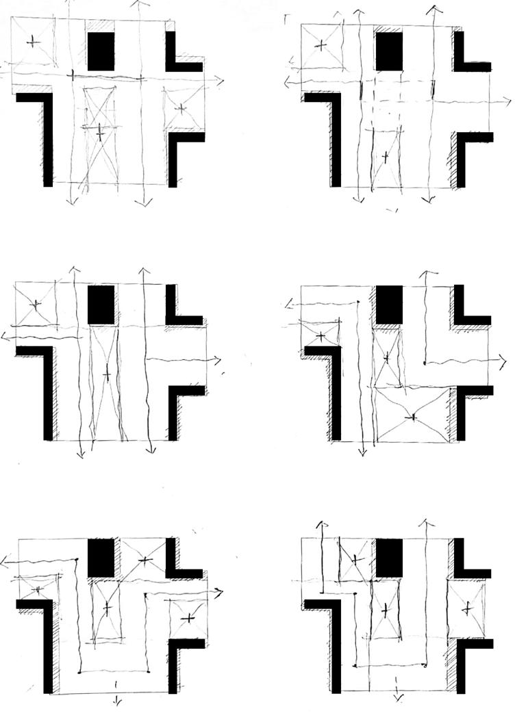
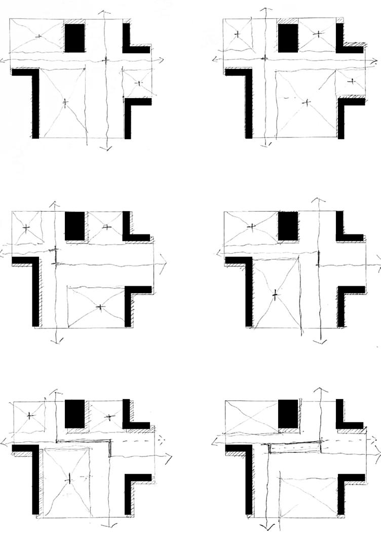
PROCESS 01 Set Rules
ZONE DIAGRAM -to creat different scale courtyard
Based on the modulus of this abstracted site, we can get some control points to help us to begin zone diagrams. The diagram starts from the most basic square, and slowly adds some elements, such as axis, circulations, intersections, etc.
34 Phase - 2
ITERATIONS
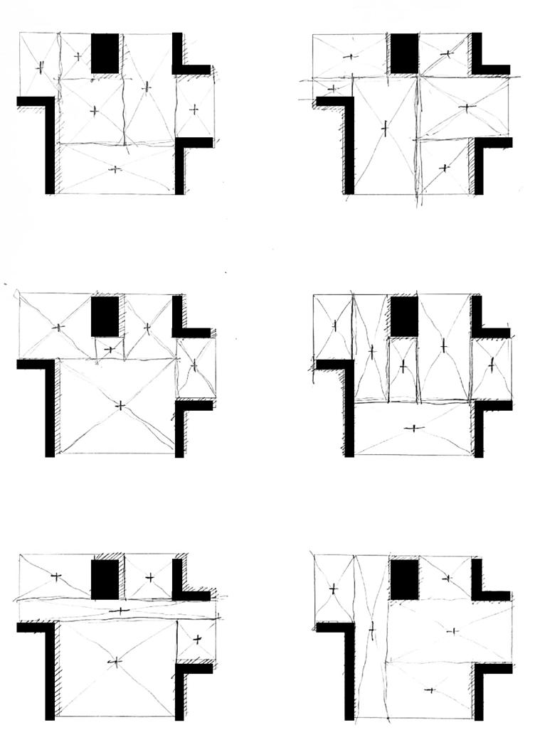
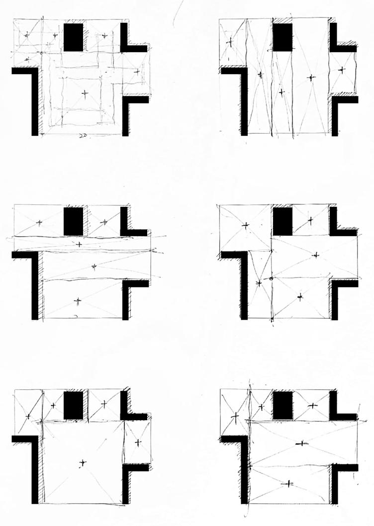
35 Spatial Generator
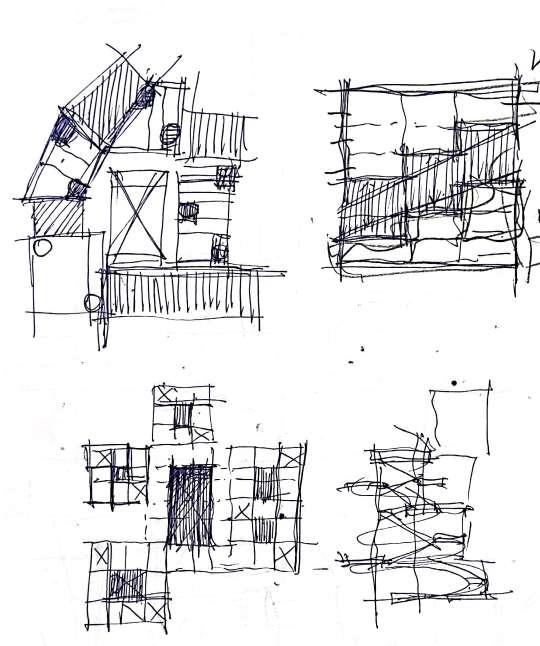
“Debating”
DEBATE ON MASS & FRAME - which is structure?
Regarding the mass and the frame, we had a discussion. Who is the structure? What is their tectonic relationship? Basically, we propose four basic prototypes: mass as core+frame as volume/ mass as core+ mass as volume/ frame as core+mass as volum/ frame as core+frame as volume. Based on this, we overlap 2 elements layer by layer.
36 Phase - 2
PROCESS 02
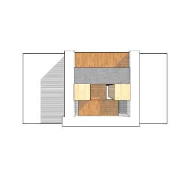
37 Spatial Generator 4 PROTOTYPES
Overlap the mass&frame
NEW COURTYARD - formed by mass & frame
The ground floor is empty, and every corner can be seen directly and unobstructed. The central area is very concentrated. Surrounding elements(mass&frame) overlap layer by layer.
38 Phase - 2
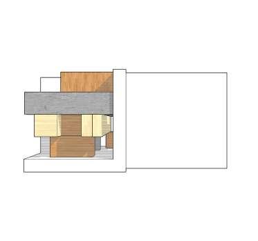
PROCESS 02
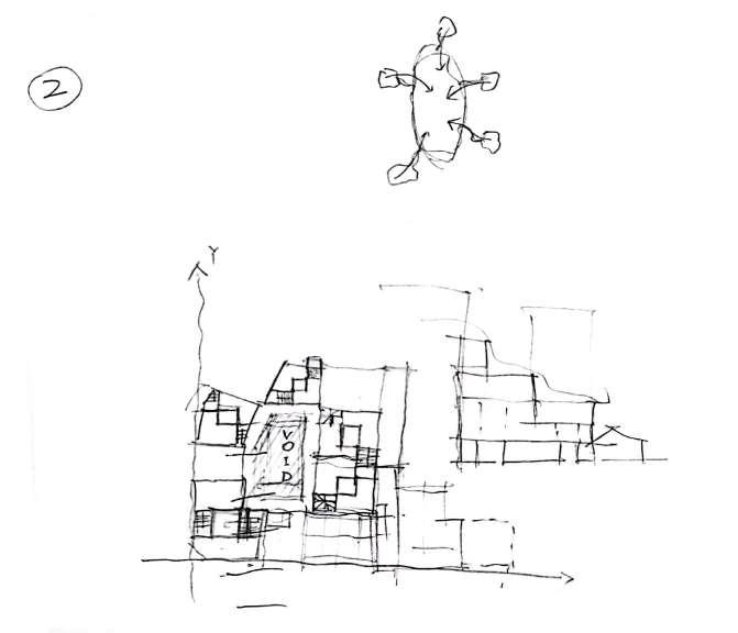
CENTRALVOID
Overlap the mass&frame
NEW HIERARCHY - to make a clera proposal
Insipired by dutch structuralism, we believe this practice is on the one hand about the making open-ended building structures by the repeated use of basic elements. In this case , the ‘Core’ and ‘Frame’ , both the elements themselves and the way they are linked are conceived to facilitate multiple uses and future growth and change.
40 Phase - 2
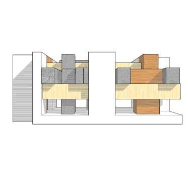
PROCESS 02
LIGHT FRAME
HEAVY FRAME
41 Spatial Generator
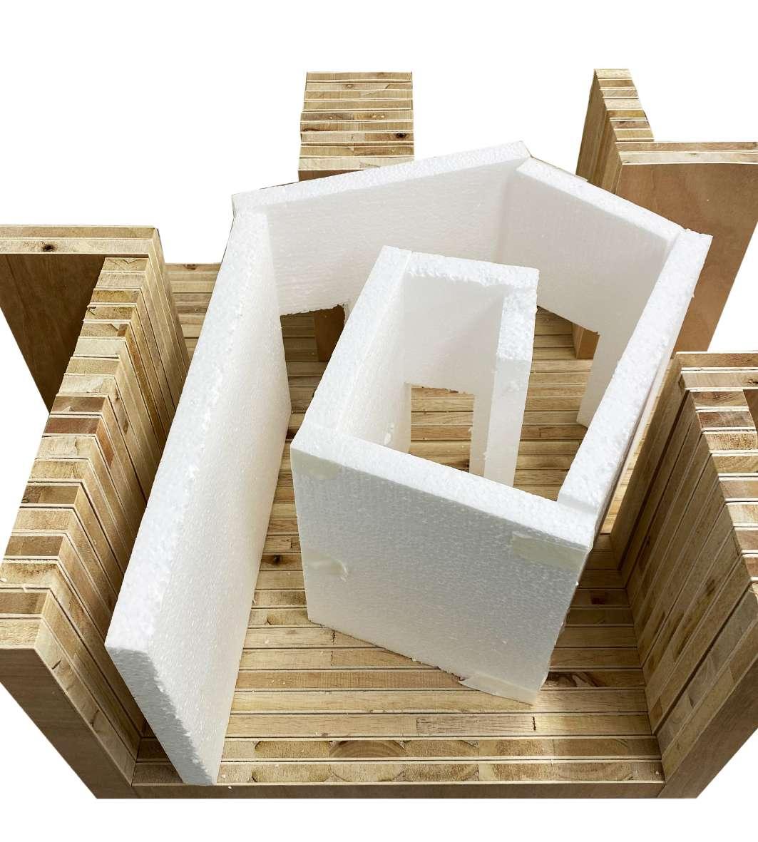
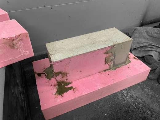
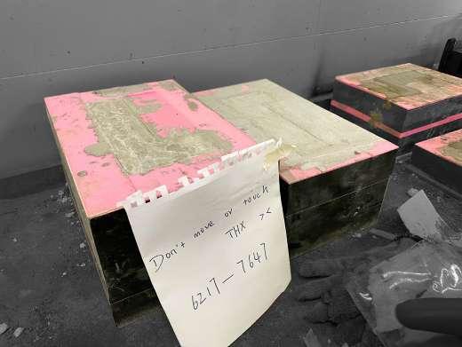
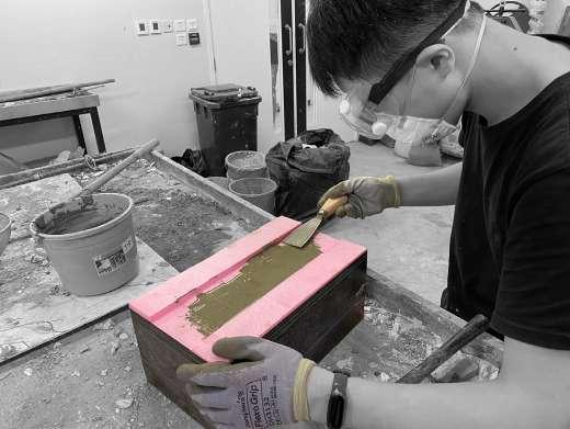
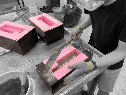
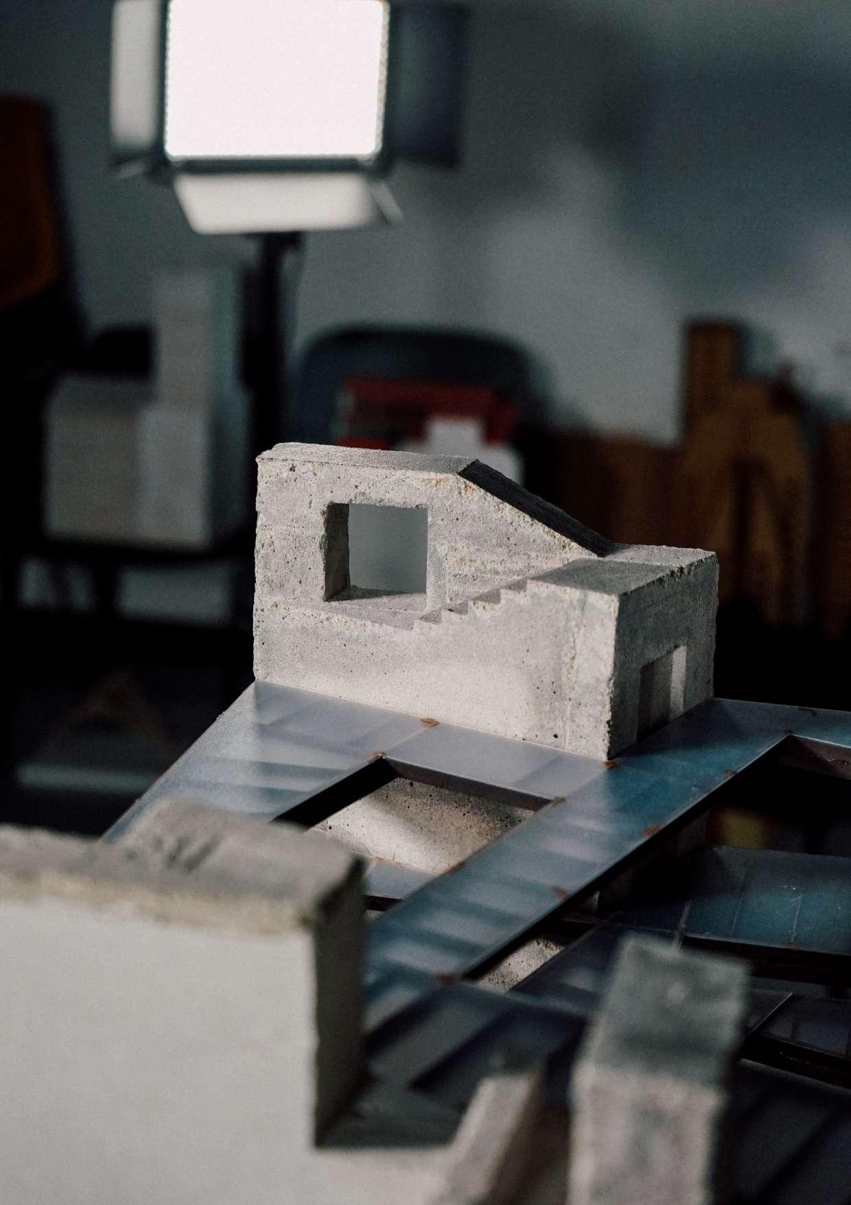
Casting the Core
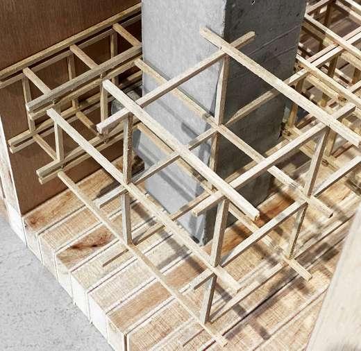
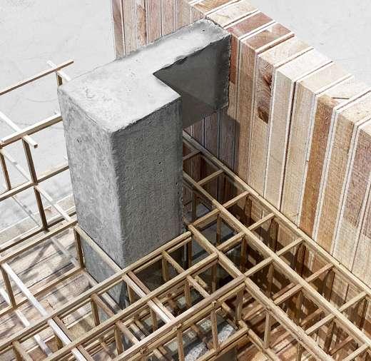
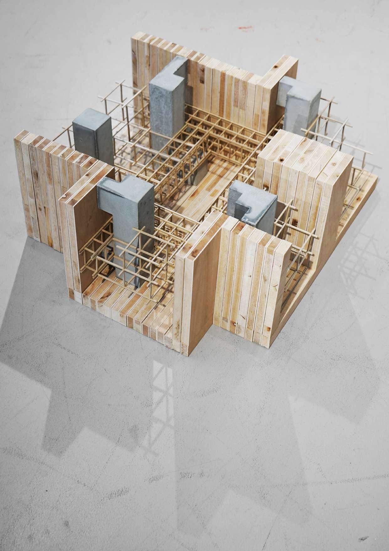
In this phase duration, we are trying to use the concrete as the physical model material for the first time. At the beginning, we use the high-density foam boards to splice together as the molds of each individual mass. The negative space formed the final concrete blocks. Through the serval times experimentations, we can conclude the cement and water and sand in ratio of 2:1:1. After fully mixing, we pour concrete into molds slowly and lightly tapped the molds side to separate the bubbles form liquid cement. The drying process duration about 24hr and blade cut foam board to take out the concrete mass.
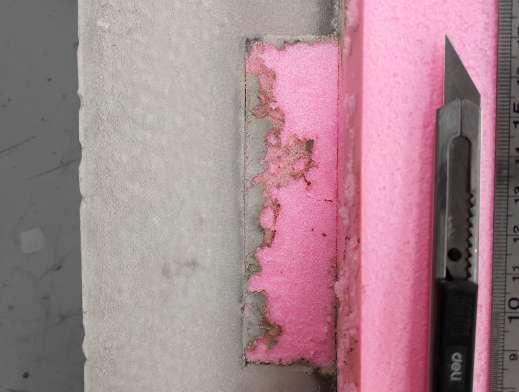
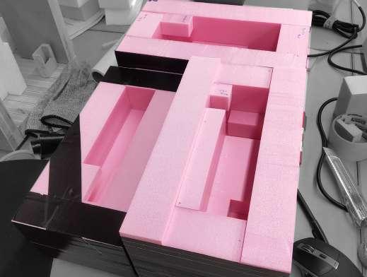
42 Phase - 2
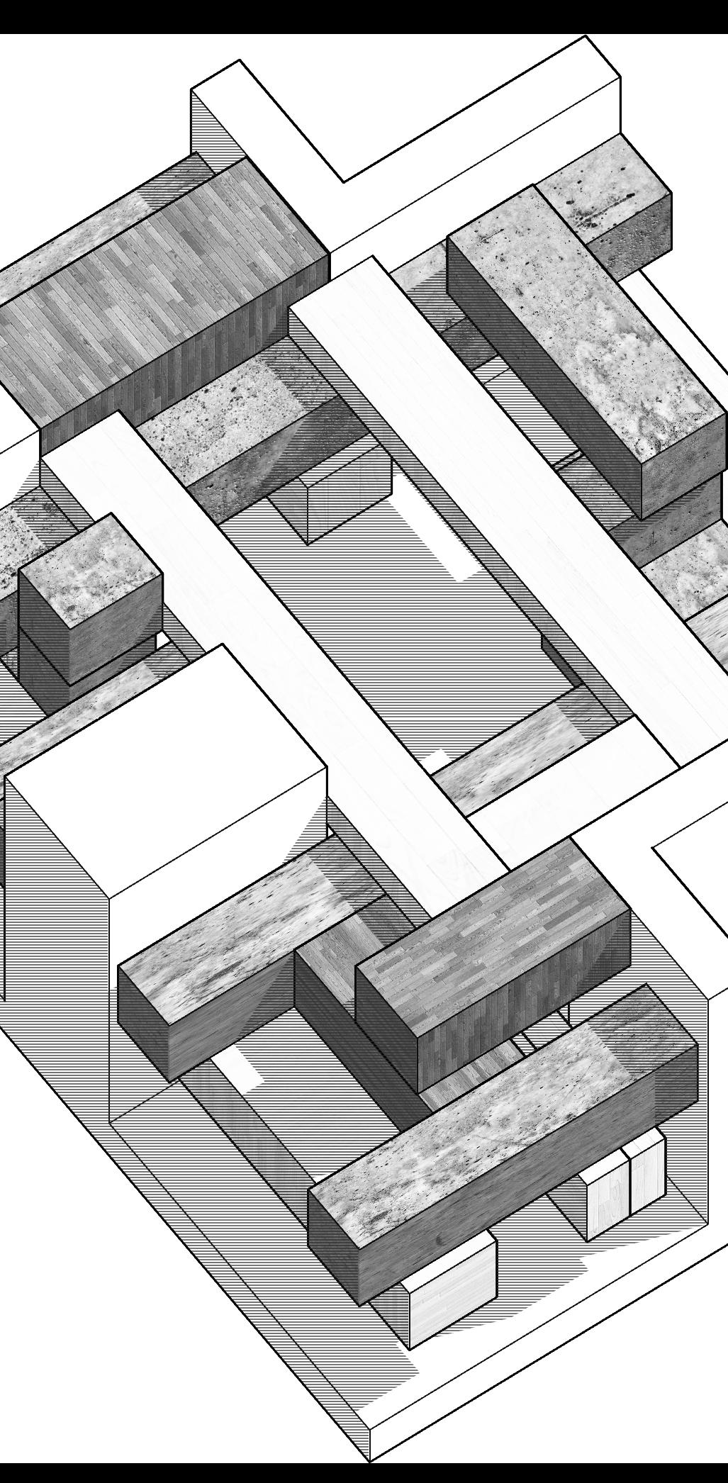
PROCESS 03
CASTING - the mass’s creative process
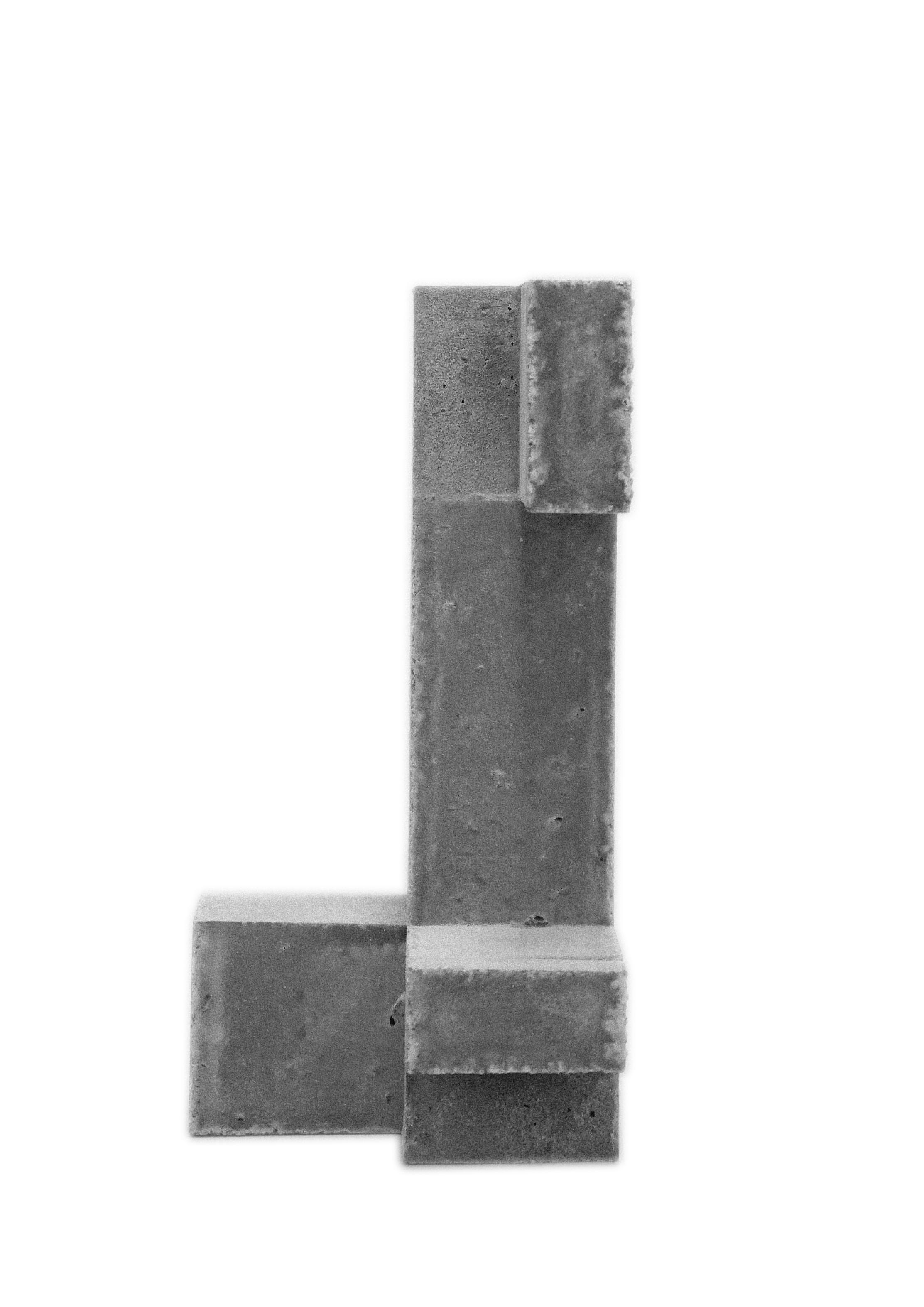
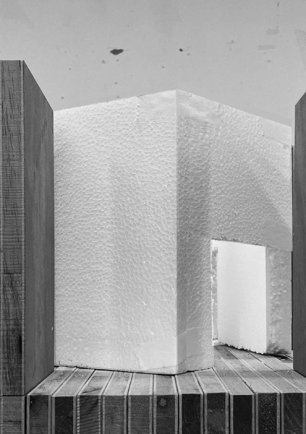
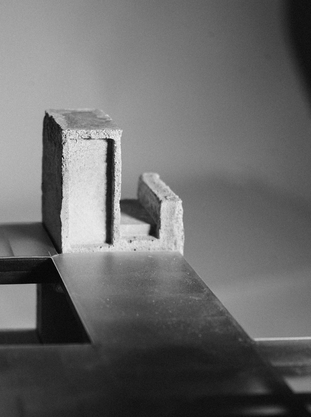
Casting the Core
CORE
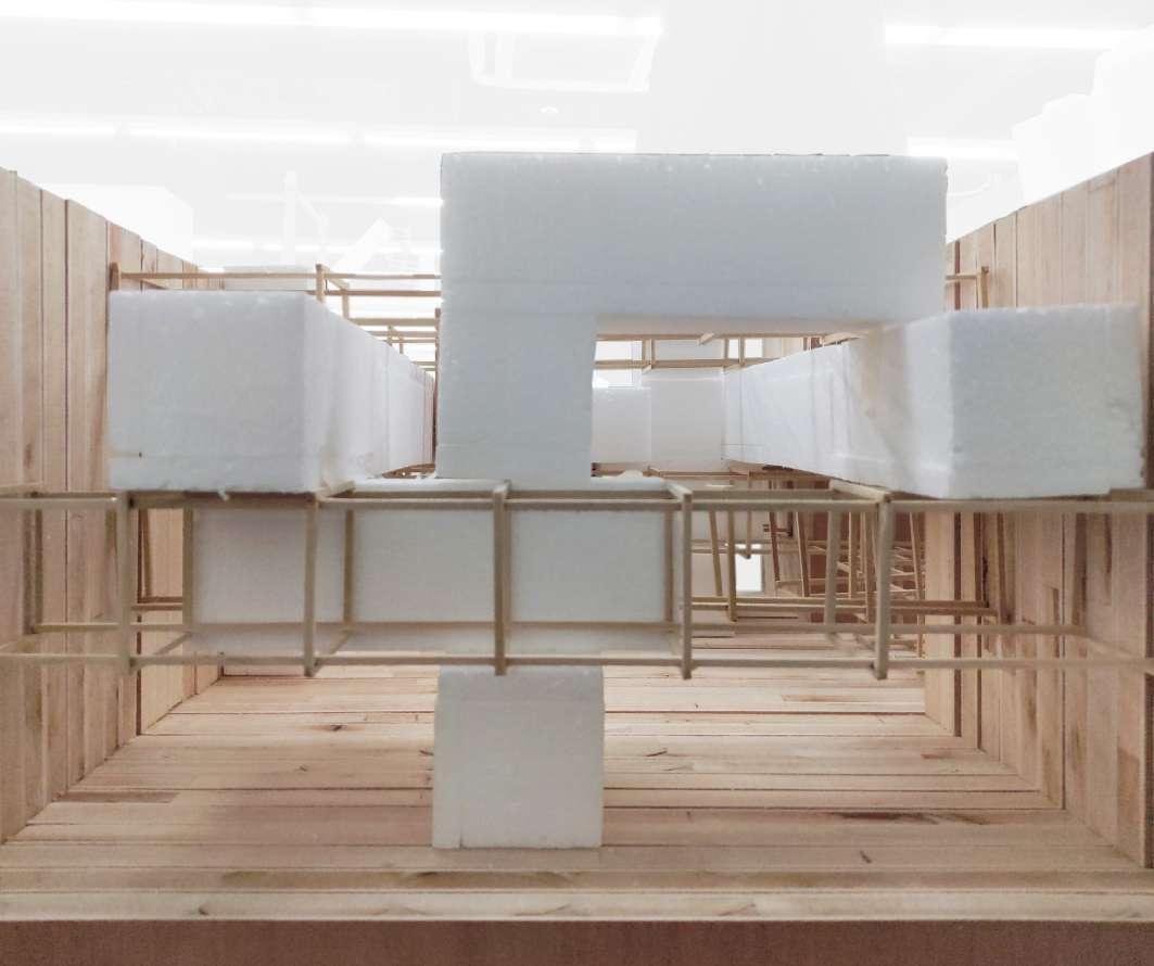
The formation of each mass space is reflecting the vertical sense of space. In this phase design, we are exploring the relationship between the mass and frame in a new perspective. The mass is not only the core tube circulation, but also include facility function, space experience, and connection with the site environment. Moreover, it also plays the role of supporting structure. In the void space, the combined five mass give the site a new sense of place.
44 Phase - 2
PROCESS 03
NEW SENSE OF SPACE
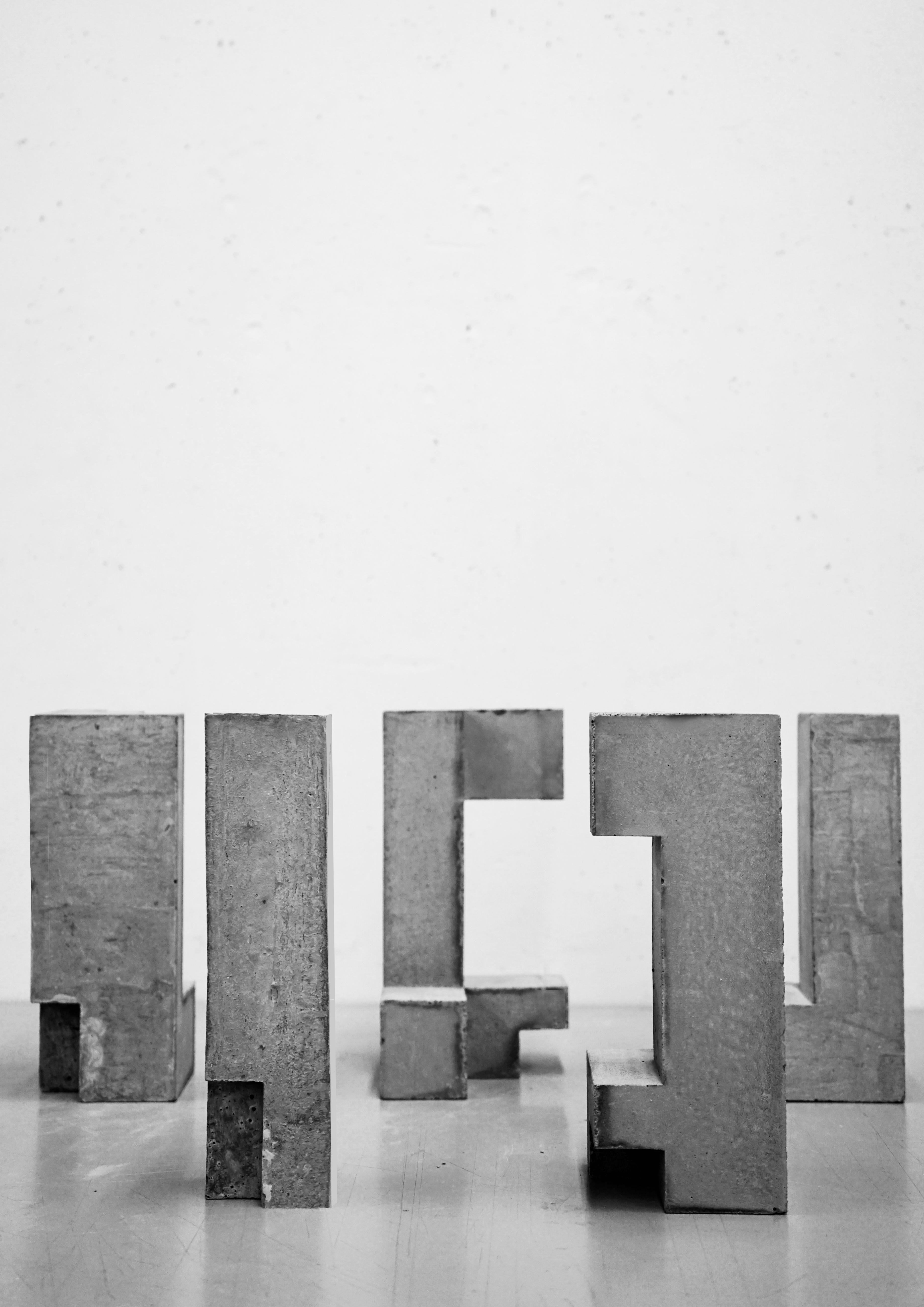
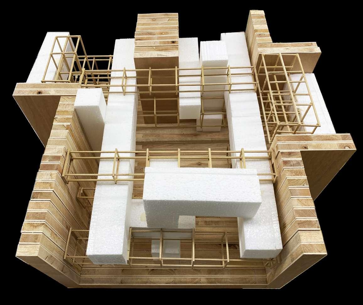
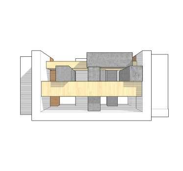
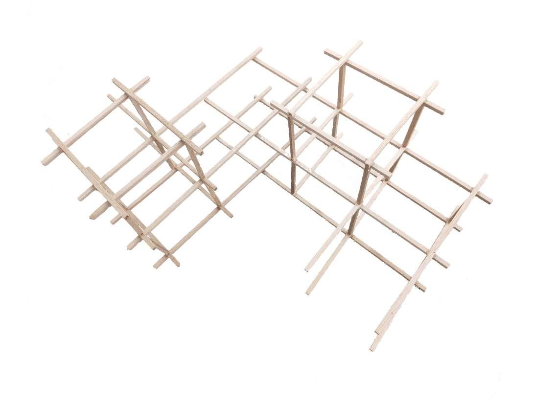
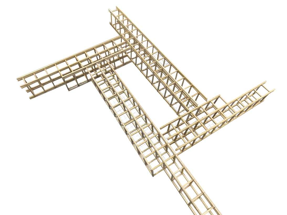
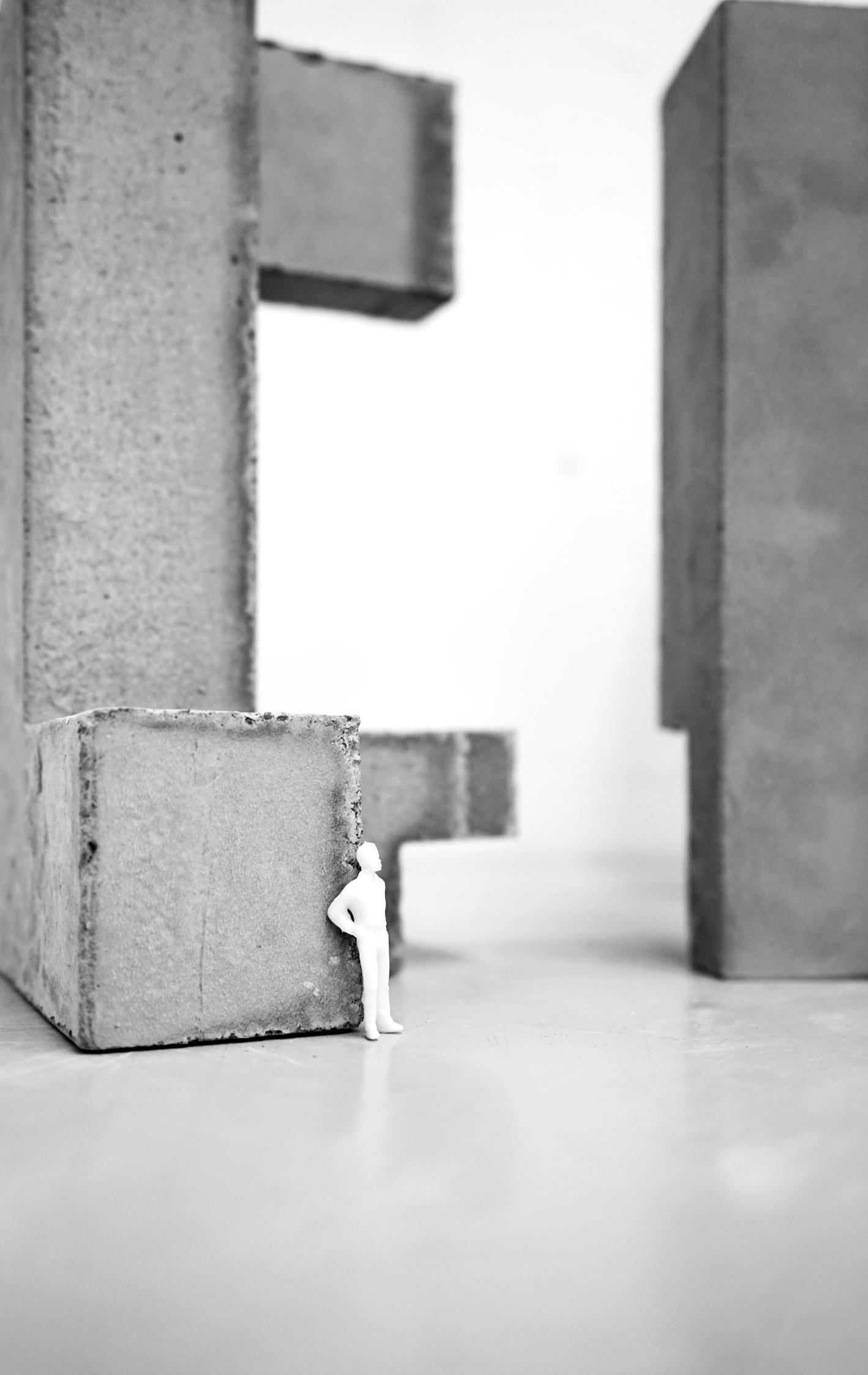
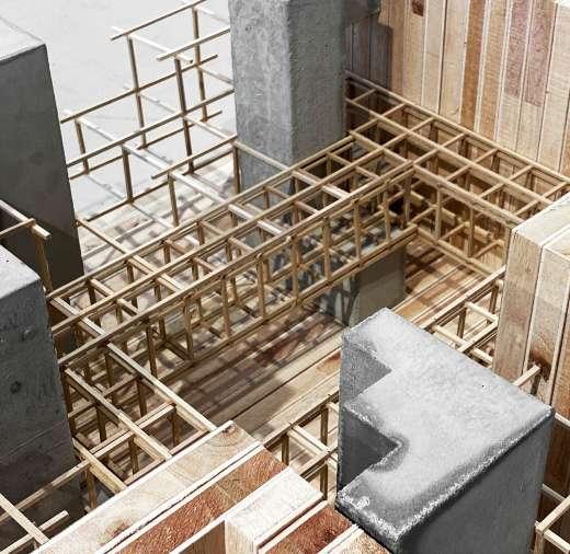
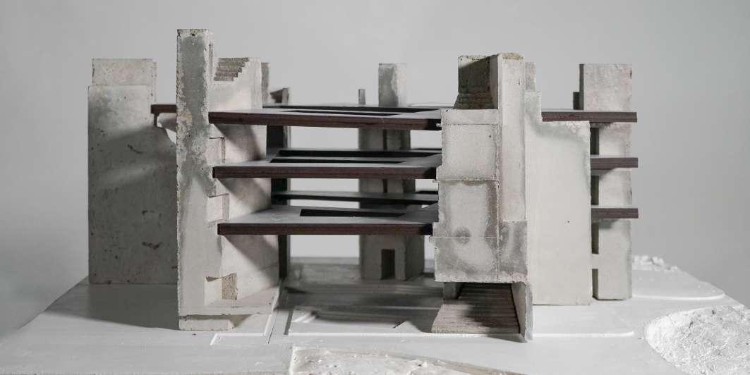
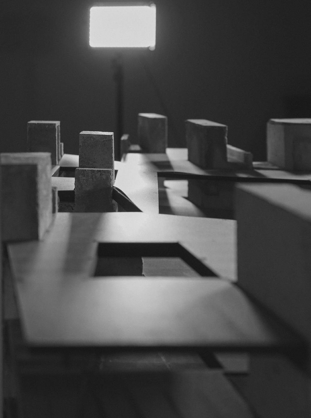
Final Model
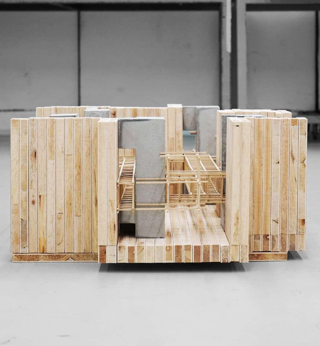
FINAL SYSTEM
This system is conceived as able to grow and change incidentally without compromising the underlying order. Change of this sort is assumed to be a feature of the future life. The contrast between simple, abstract, orderly patterns and disordered existing patterns is marked, as schemes for the systemic orientation emphasizes the dimensionless underlying order, which remains despite additions and subtractions.
46 Phase - 2
47 Spatial Generator
48 Phase - 2
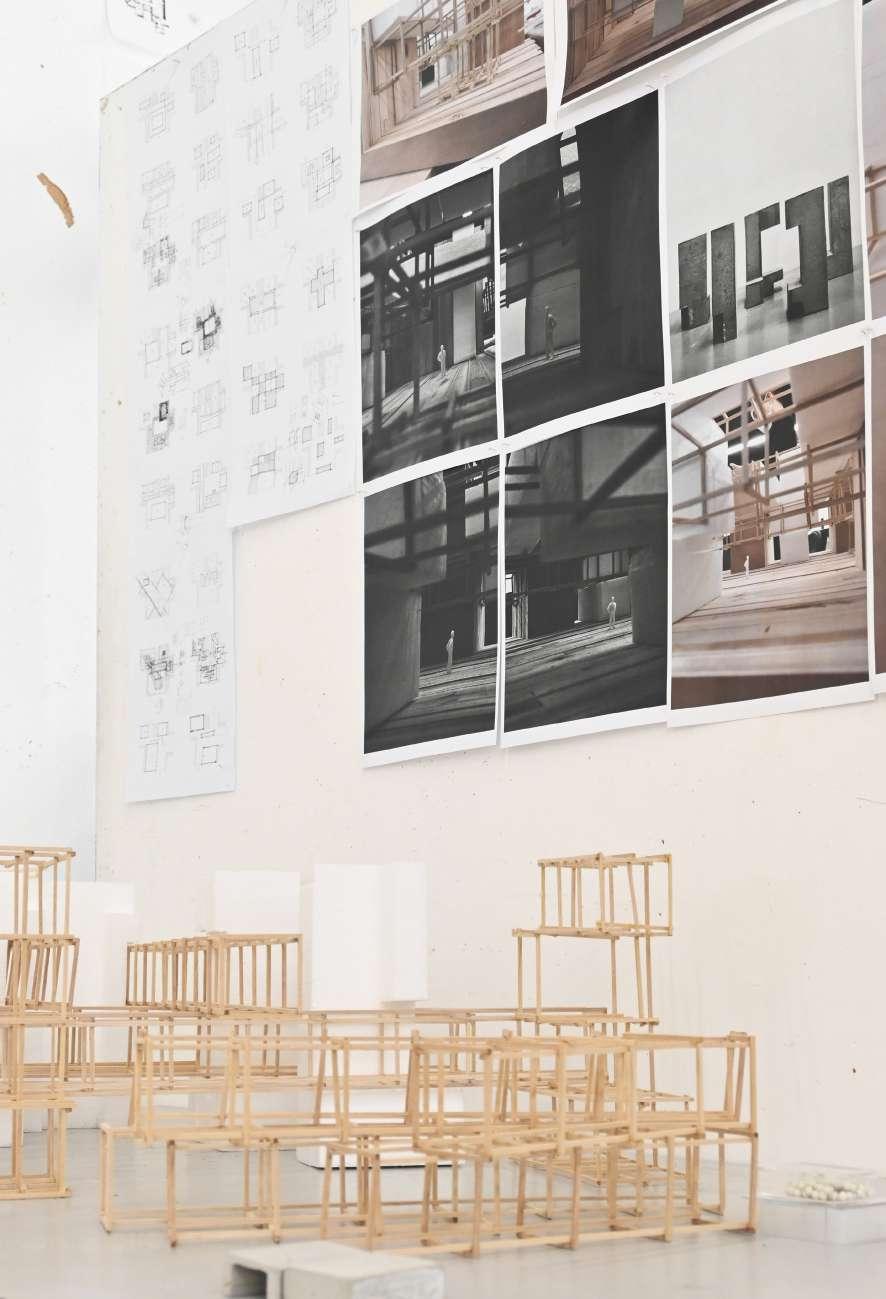
Review
FINAL MODEL
50
SITUATING + ADAPTING PHASE 3:
51
3
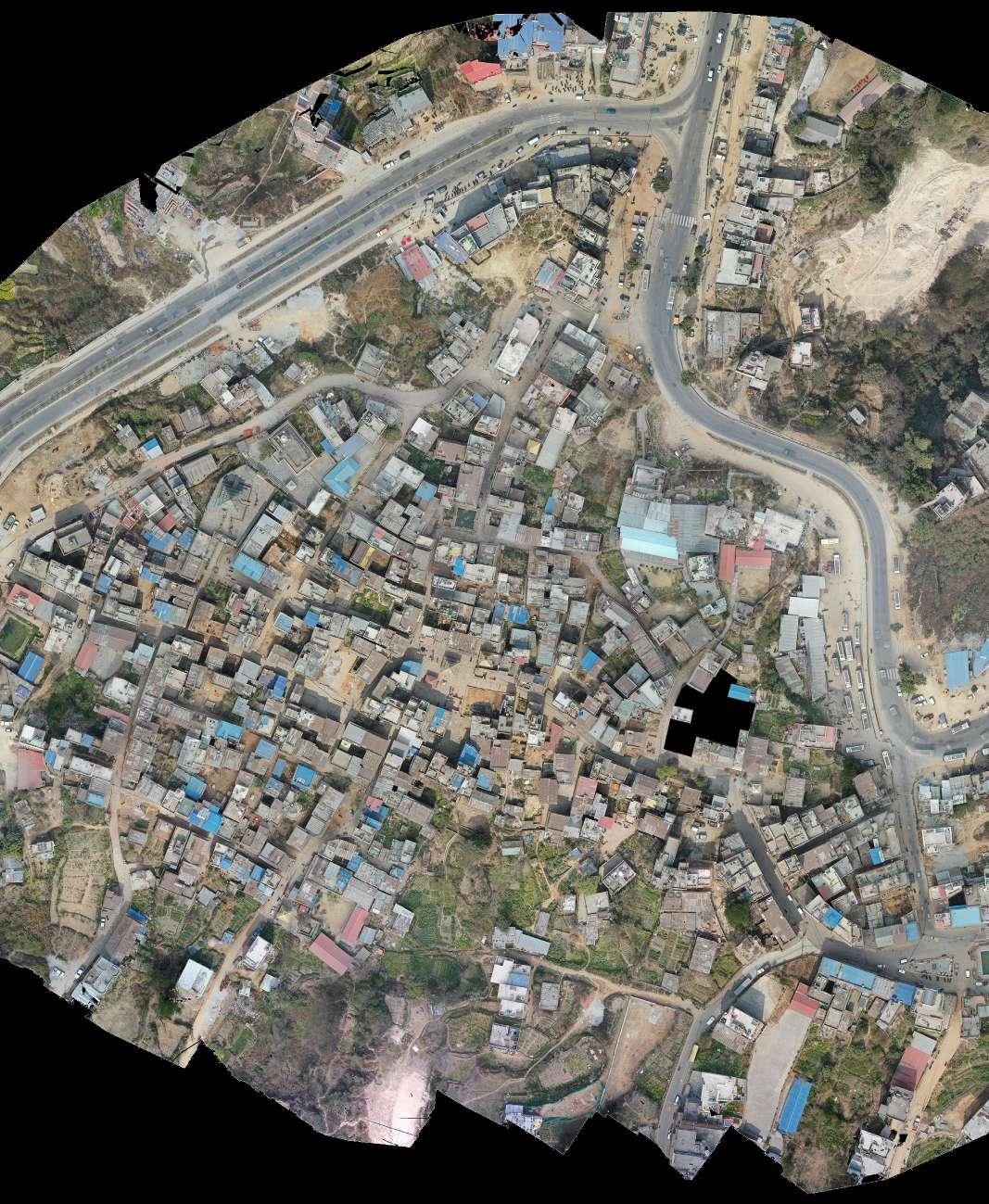
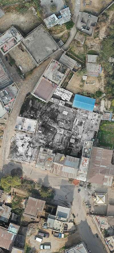
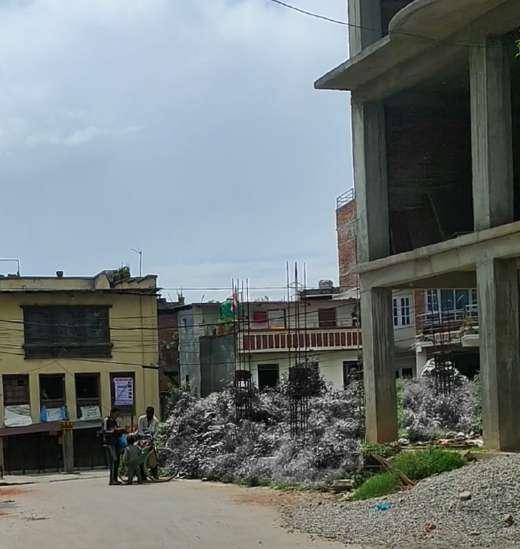
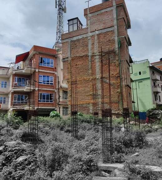
“Broken Courtyard”
52 Phase - 3
Site Location
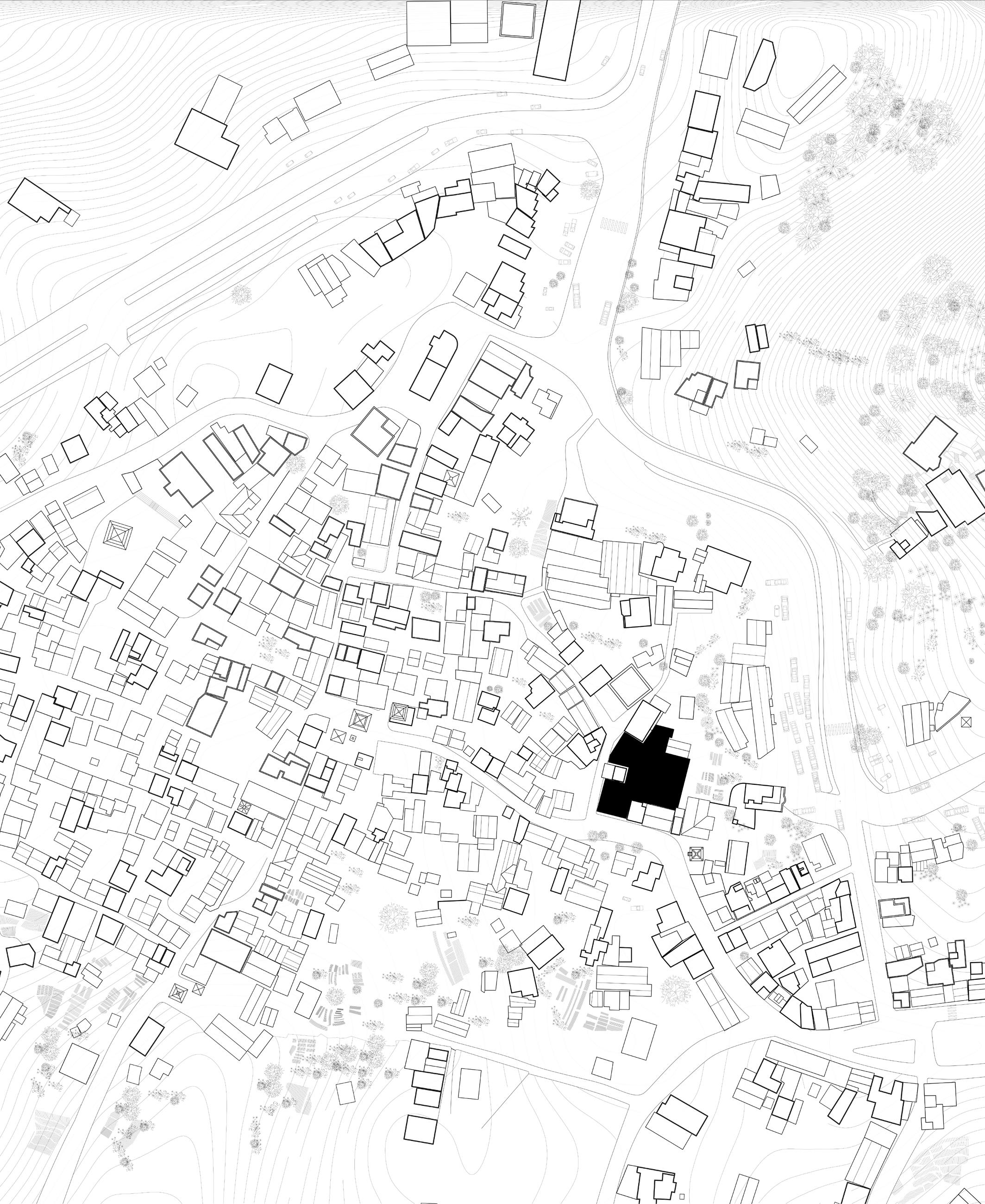
53 Situating + Adapting
Ruin & Rule
SETTING RULES BASED ON “PHASE 2”
This system is conceived as able to grow and change incidentally without compromising the underlying order. Change of this sort is assumed to be a feature of the future life. The contrast between simple, abstract, orderly patterns and disordered existing patterns is marked, as schemes for the systemic orientation emphasizes the dimensionless underlying order, which remains despite additions and subtractions.
54 Phase - 3
Pushing in 2D
55 Situating + Adapting
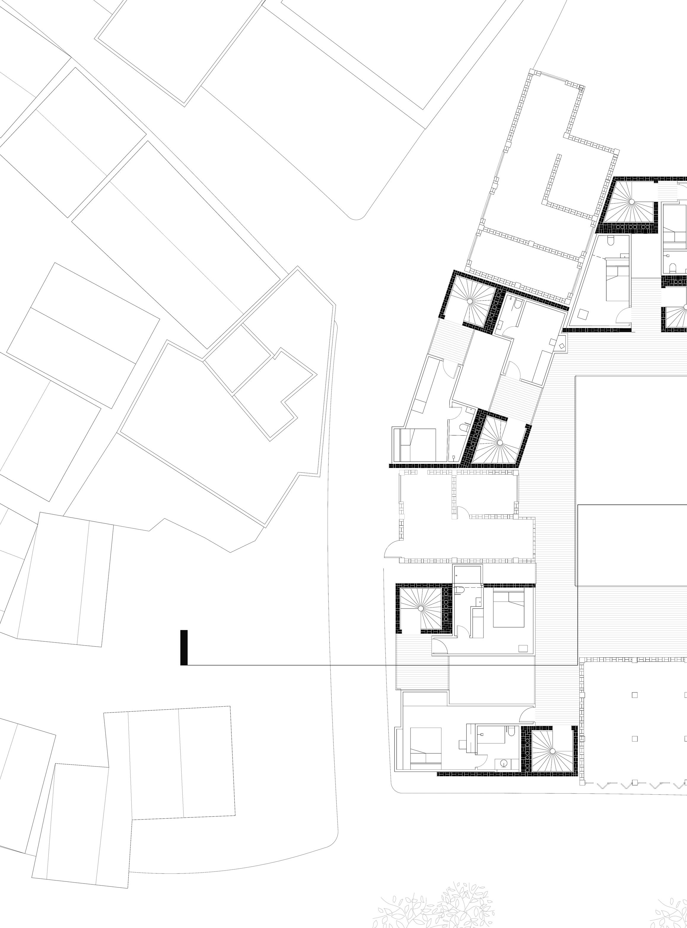
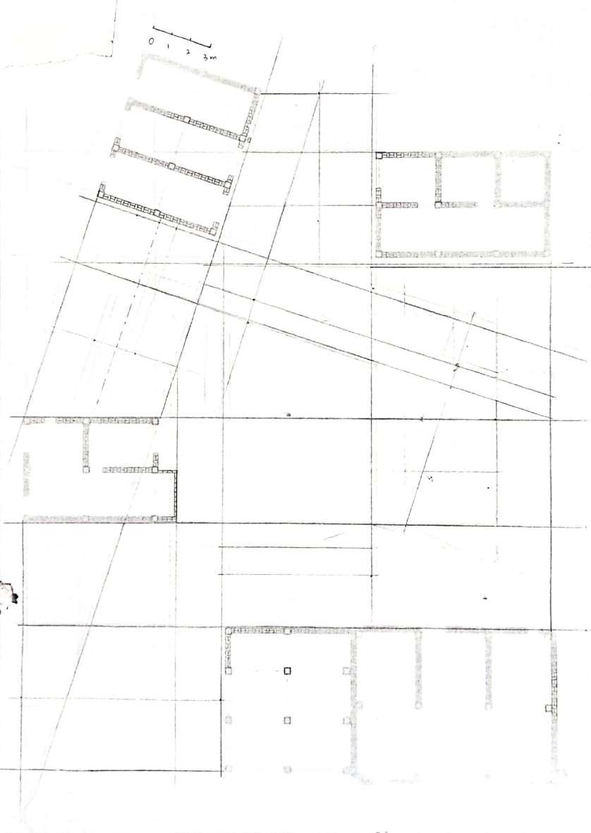
Plan diagram
56 Phase - 3 SIMPLE GRID
Pushing in 2D
57 Situating + Adapting ADAPT TO THE EXISTING BUILDING
Plan diagram
58 Phase - 3 SET SCHEME BOUNDARY
Pushing in 2D
59 Situating + Adapting UNIFORM THE BOUNDARY
60 Phase - 3 ADD GIRD
Pushing in 2D
Plan diagram
61 Situating + Adapting FIT THE GRID INTO THE COUNDARY
62 Phase - 3 ADD GIRD
Pushing in 2D
Plan diagram
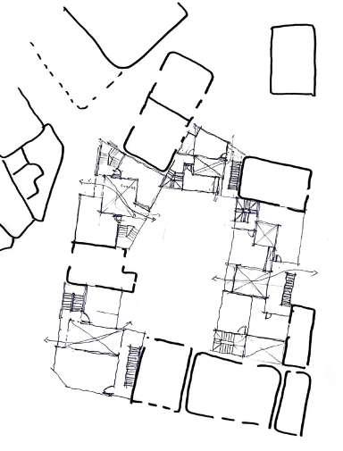
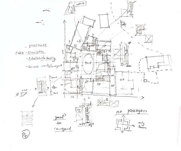
63 Situating + Adapting
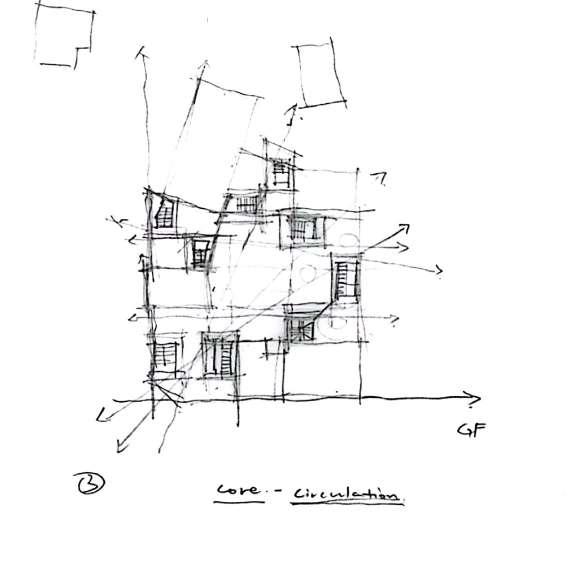
FIT THE GRID INTO THE COUNDARY AND SET THE CORE
Plan diagram
64 Phase - 3 SET
CORES AND INFRASTRUCTURE
Pushing in 2D
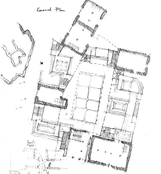
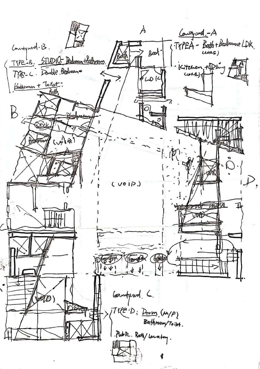
65 SKETCHES
Plan Iteration 1
66 Phase - 3 Pushing in 2D
67 Situating + Adapting
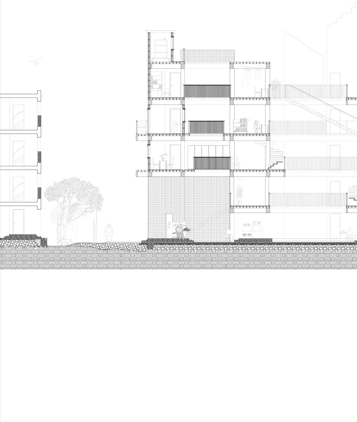
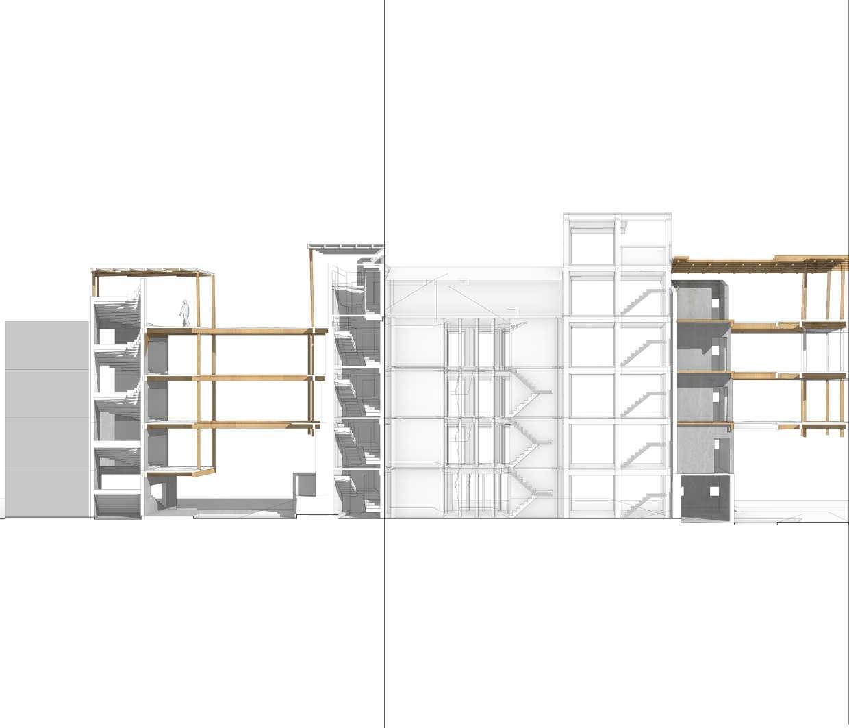
Section Iteration 1
68 Phase - 3 Pushing in 2D
69 Situating + Adapting
Section Iteration 2
70 Phase - 3 Pushing in 2D
71 Situating + Adapting
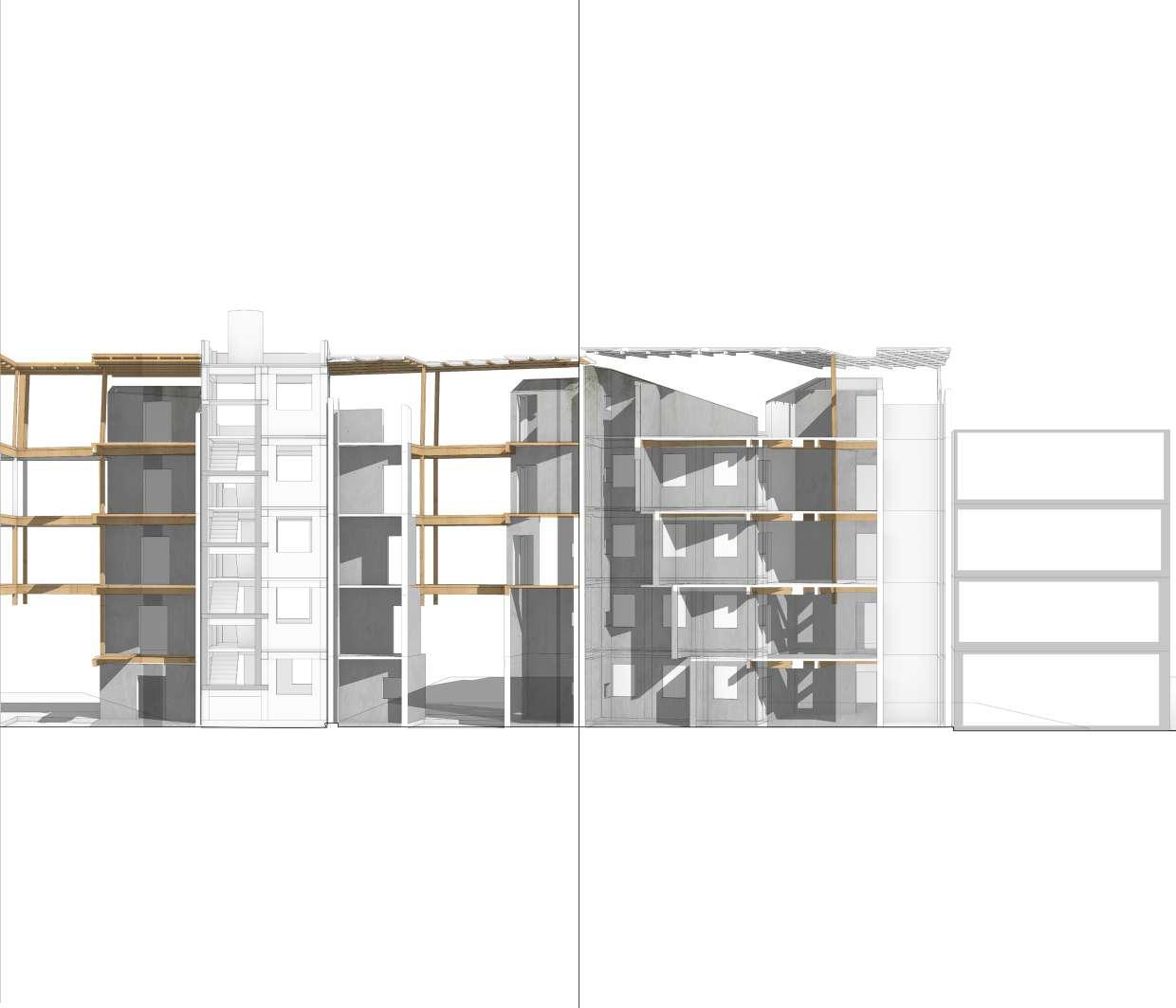
Section Iteration 3
72 Phase - 3 Pushing in 2D
73 Situating + Adapting
Section Iteration 4
74 Phase - 3 Pushing in 2D
75 Situating + Adapting
Model Iteration 1
76 Phase - 3
Pushing in 3D
Plan diagram
78 Phase - 3 ADAPTING ORIGINAL GRID
Pushing in 2D
79 Situating + Adapting SETTING PROGRAMS
80 Phase - 3 FREEZE THE PLAN
Pushing in 2D
Plan diagram
TESTING THE GRID IN RHINO
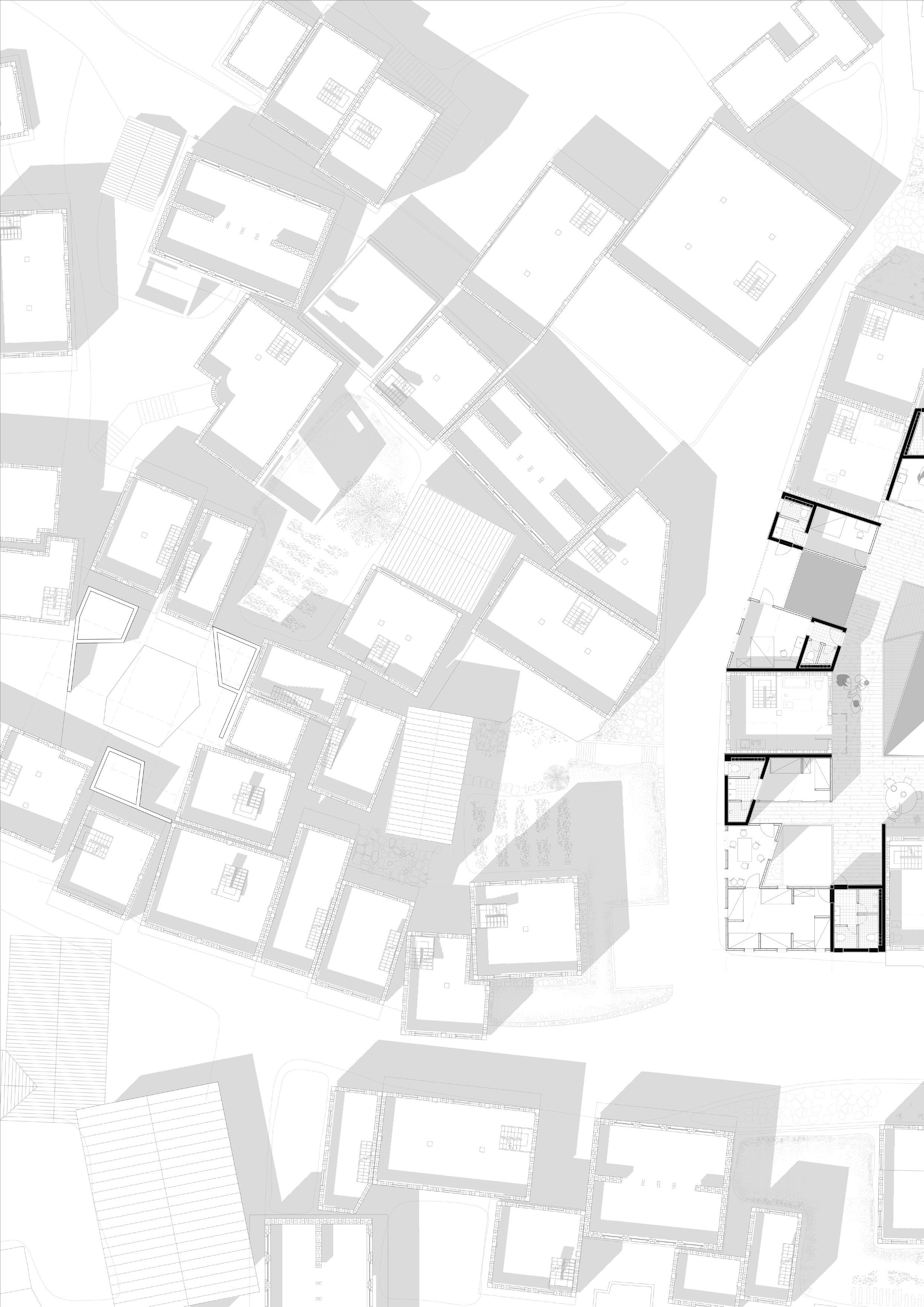
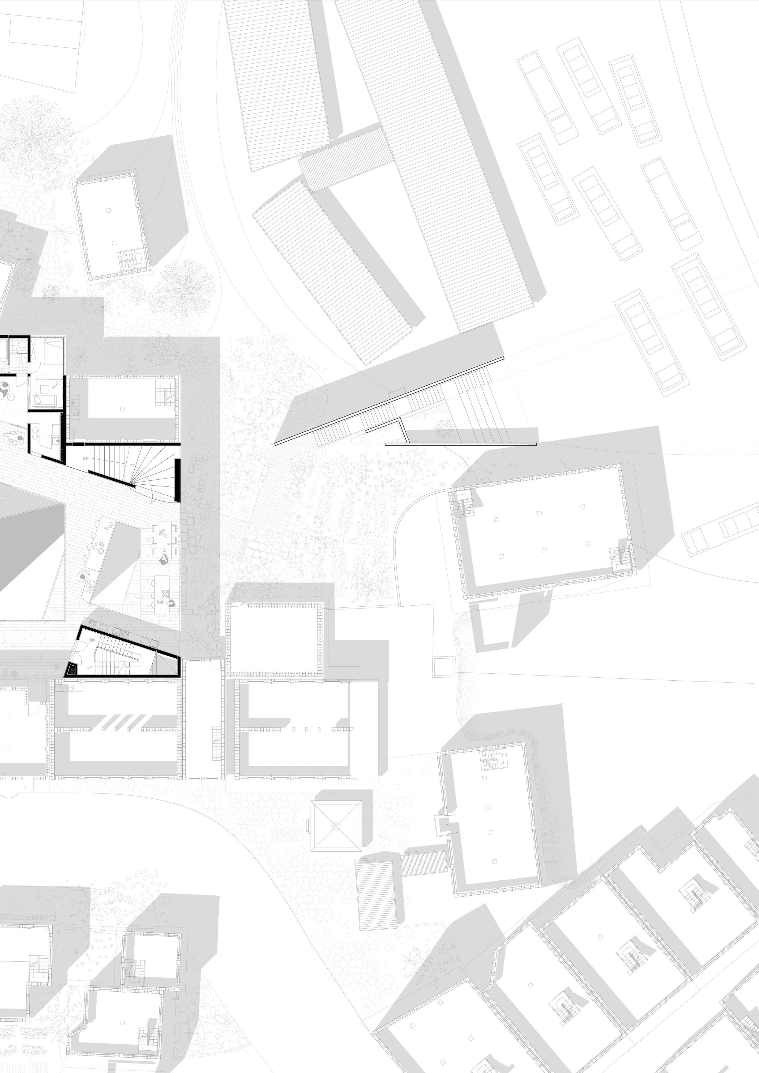
81 Situating + Adapting
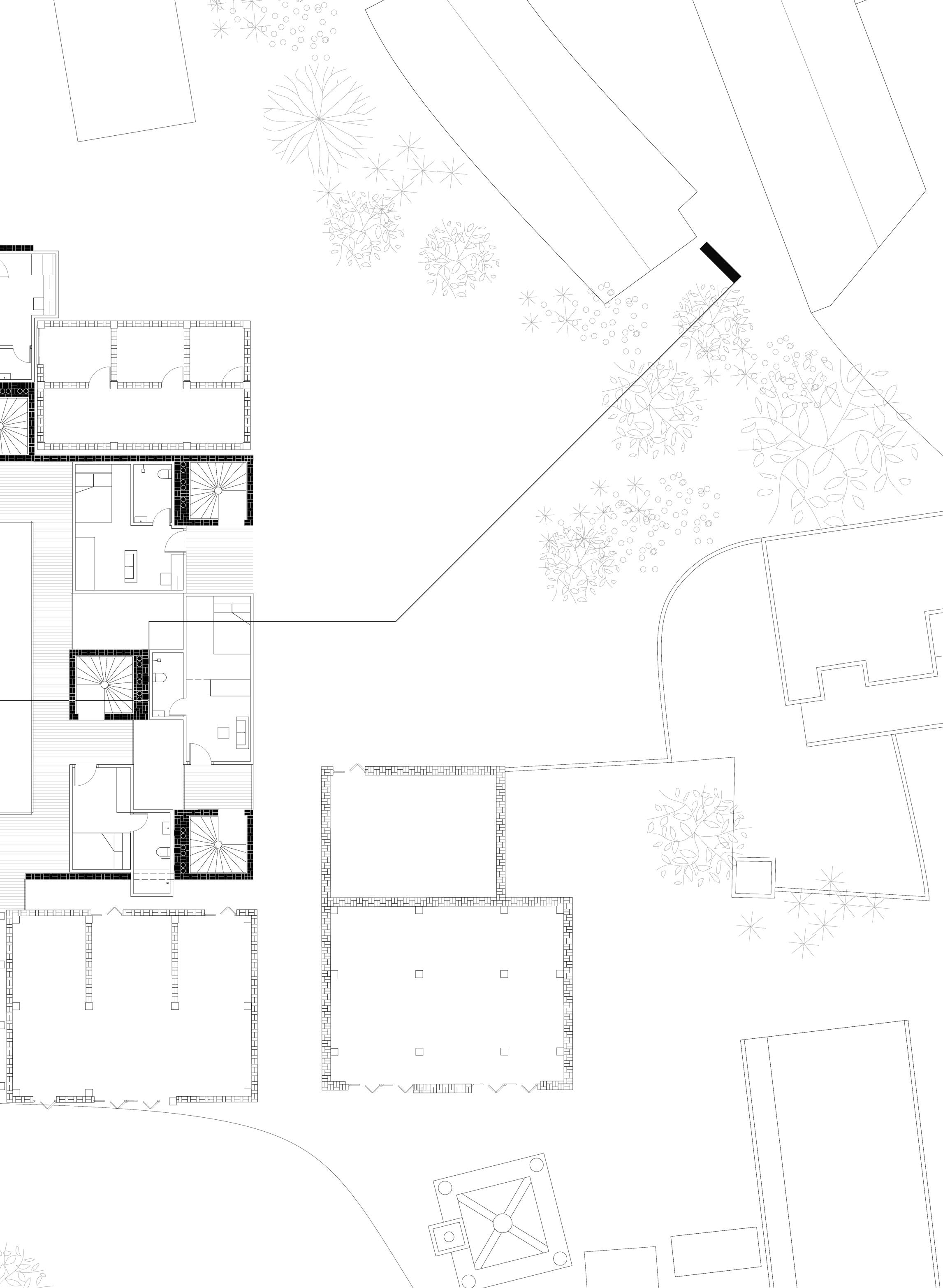
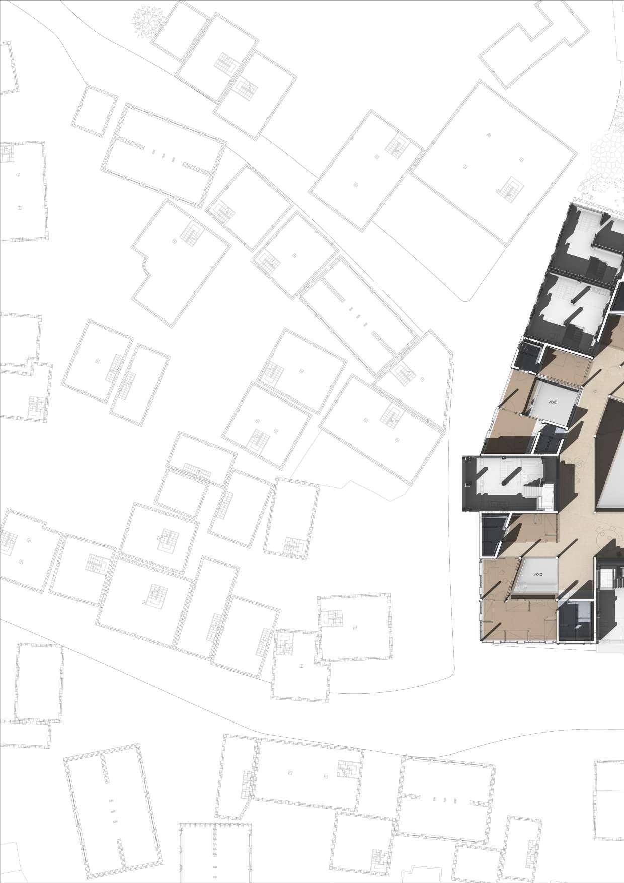
Landscape Drawing
82 Phase - 3 UP
Pushing in 2D
83 Situating + Adapting
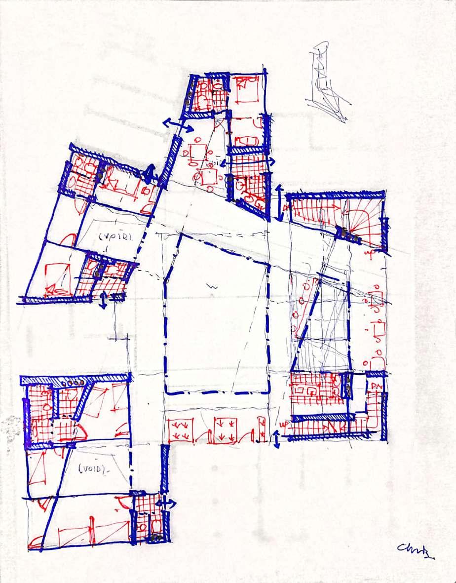
Plan Iteration 2 - Line Drawing
84 Phase - 3 VOID VOID Testing
2D
in
85 Situating + Adapting DN VOID UP DN UP VOID
Plan Iteration 3 - Collage
Testing in 2D
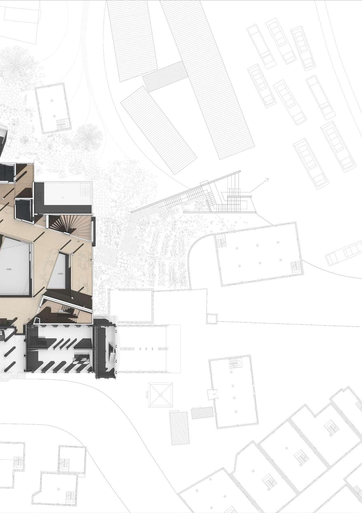
Pushing in 2D
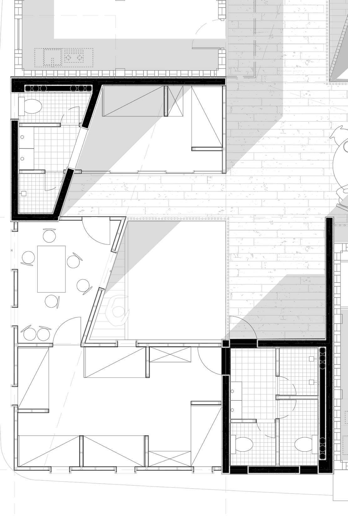
Plan - Housing Types
HOUSING TYPE A - SINGLE ROOM
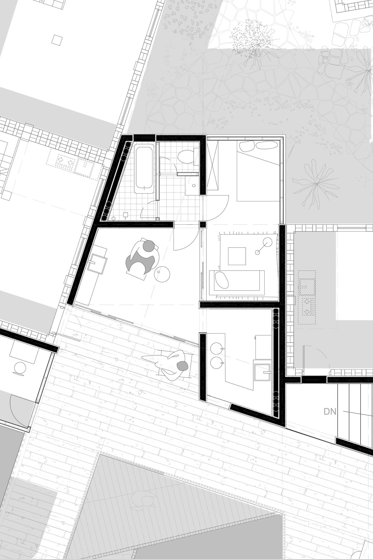
88 Phase - 3
HOUSING TYPE B - DOUBLE ROOM
89 Situating + Adapting
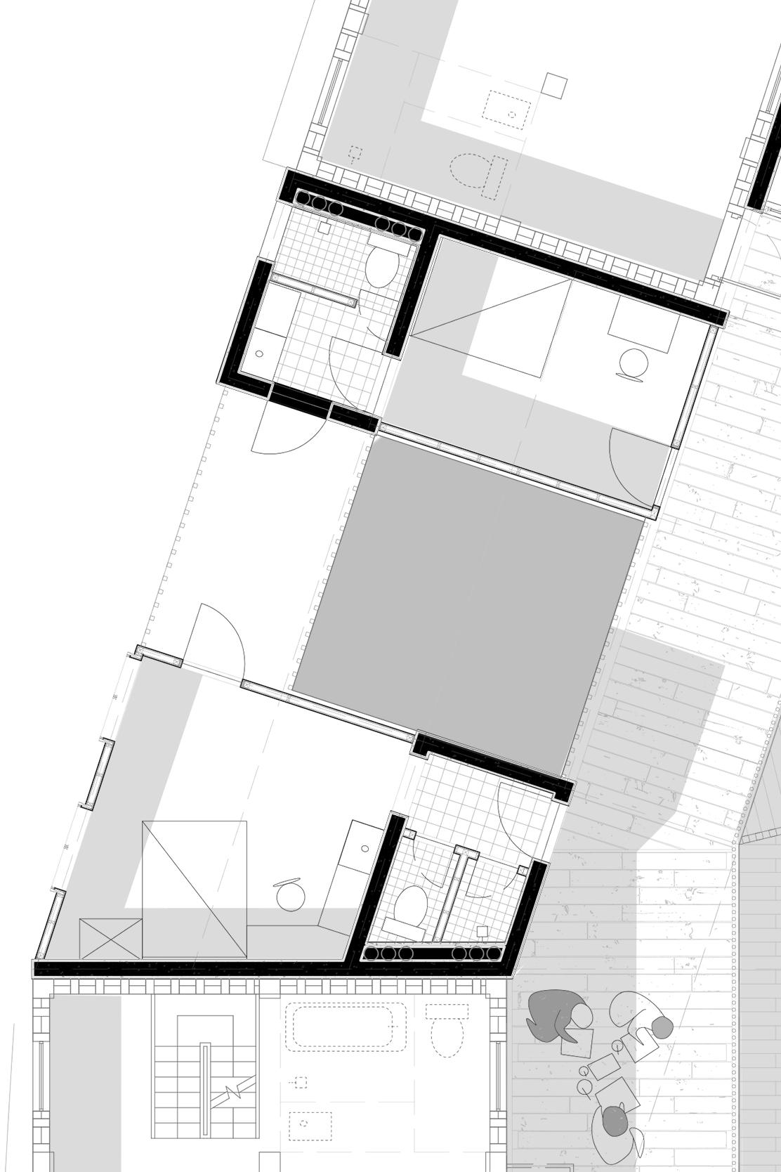
Pushing in 2D
Plan - Housing Types
HOUSING TYPE C - YOUTH HOSTEL
90 Phase - 3
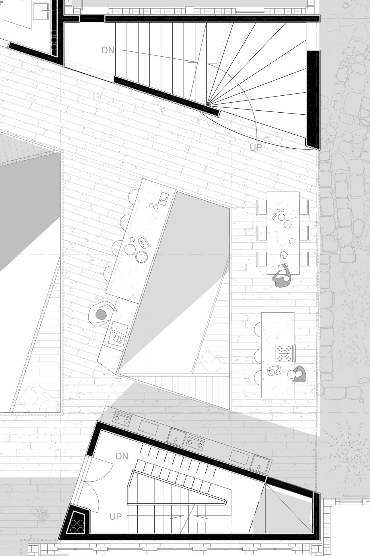
91 Situating + Adapting PUBLIC PLATFORM
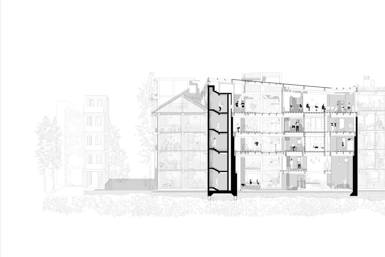
Section Iteration 3 - Black white
Pushing in 2D
Section Iteration 5
94 Phase - 3 Testing in 2D
95 Situating + Adapting
Section Iteration 6
96 Phase - 3 Testing in 2D
97 Situating + Adapting
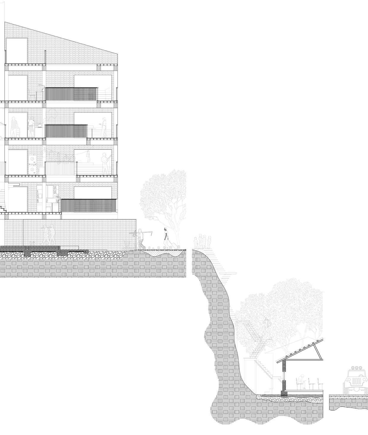
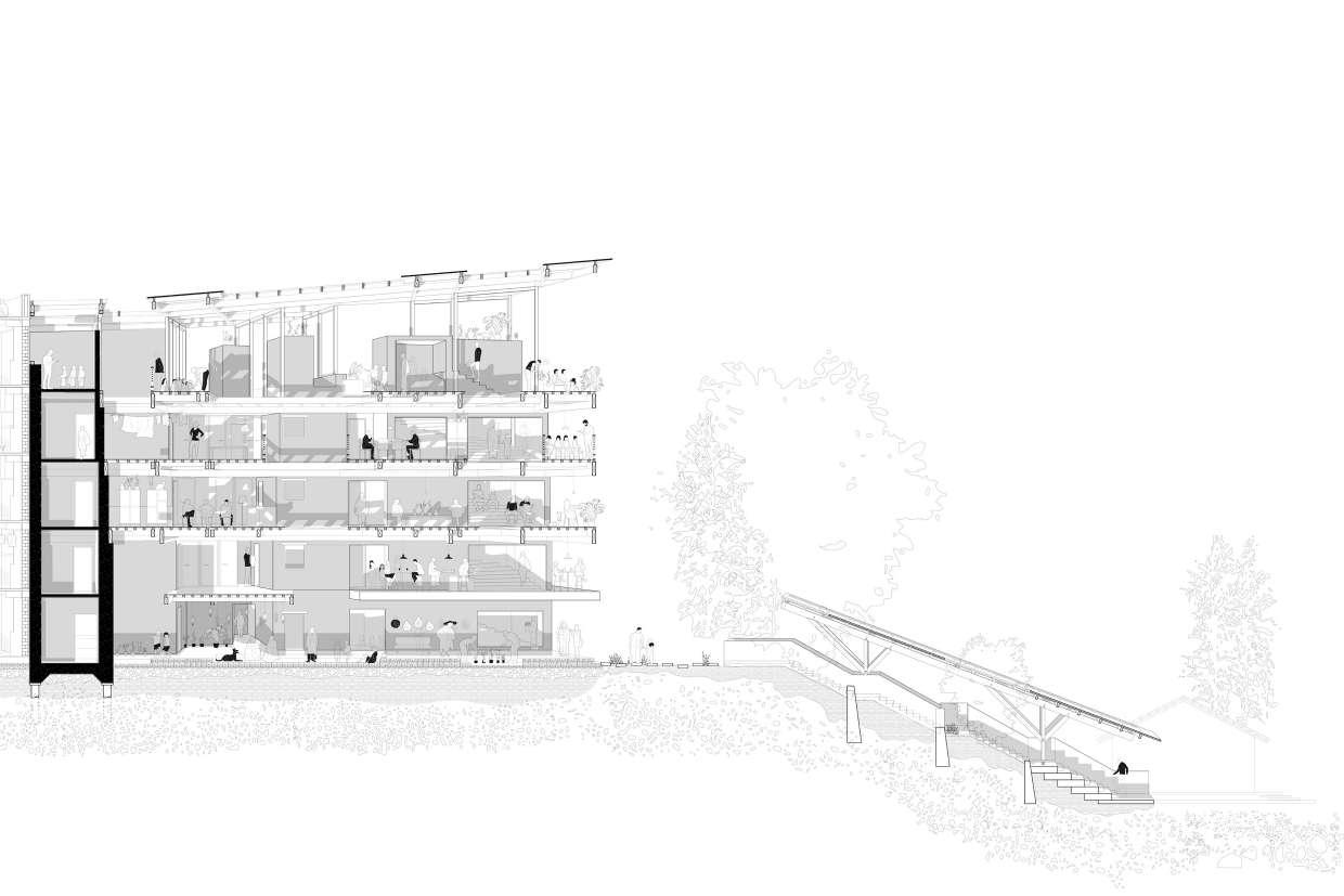
Section - Living Scence
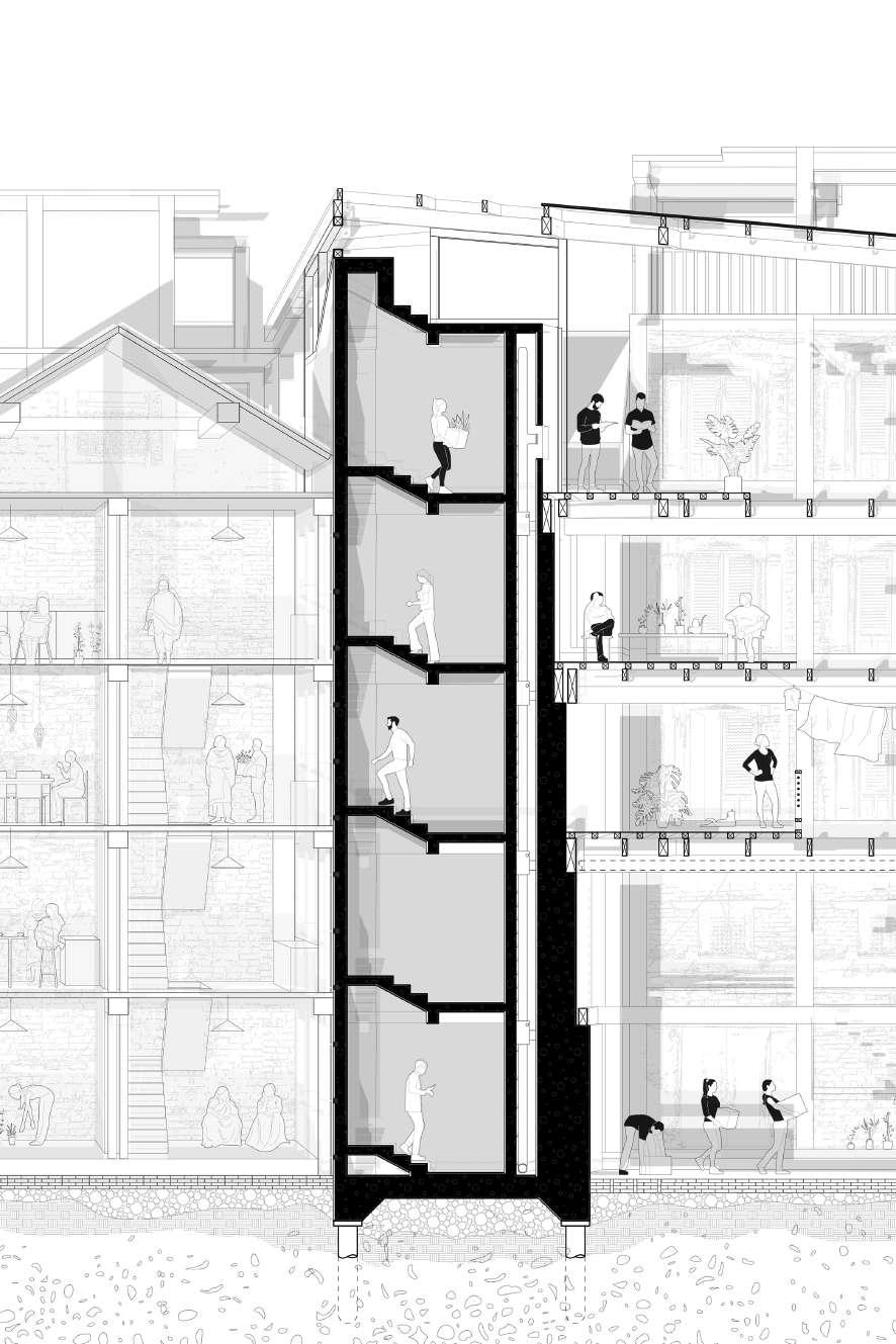
98 Phase - 3 CORE TO CONNECT PAST&FUTURE Pushing in 2D
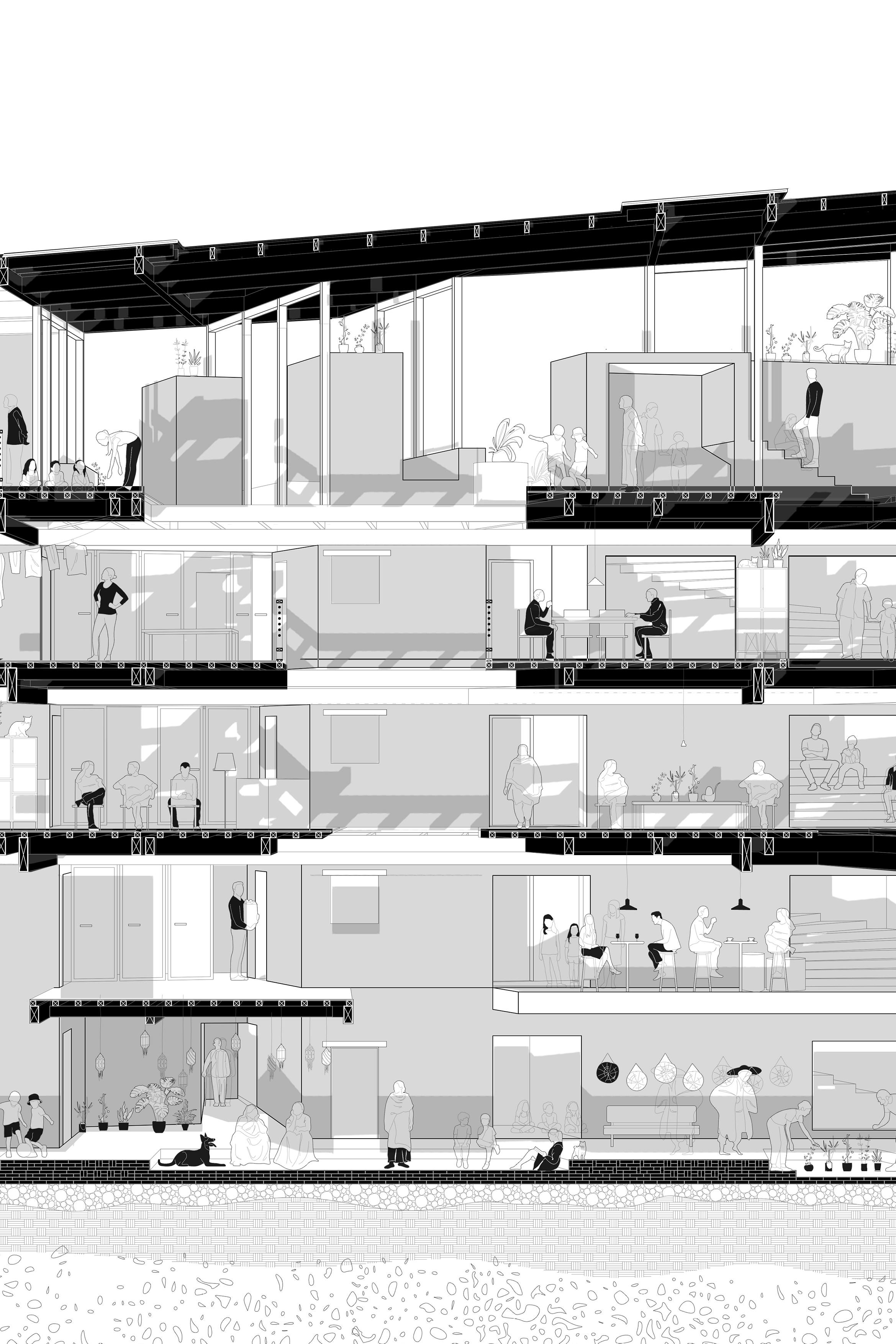
99 Situating + Adapting LIVING
IN PLATFORM
Section Final
100 Phase - 3 Pushing in 2D
101 Situating + Adapting
Pushing in 3D
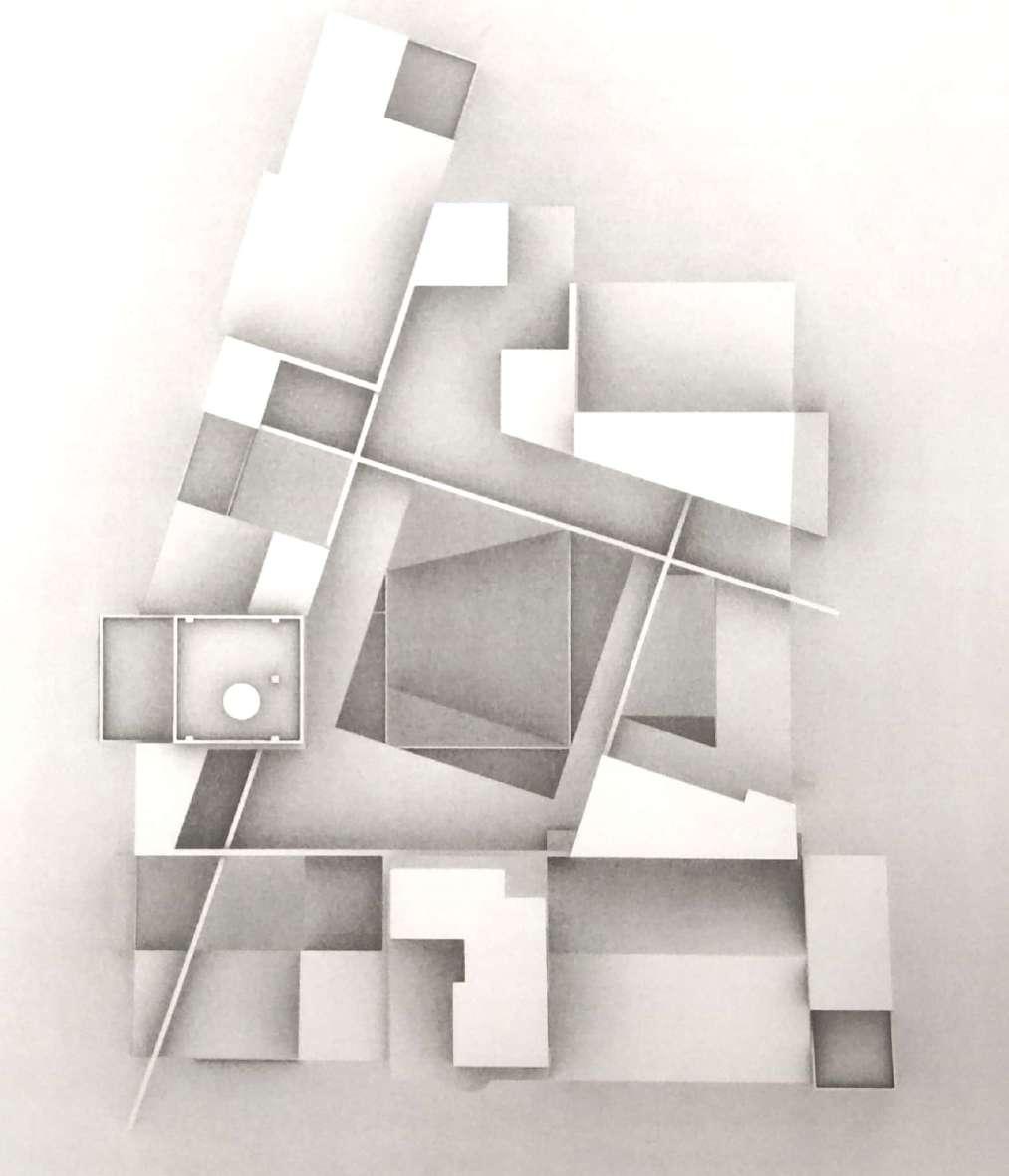
Model Iteration 2
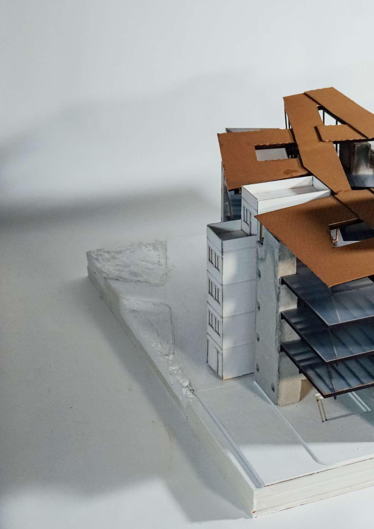
Physical Model
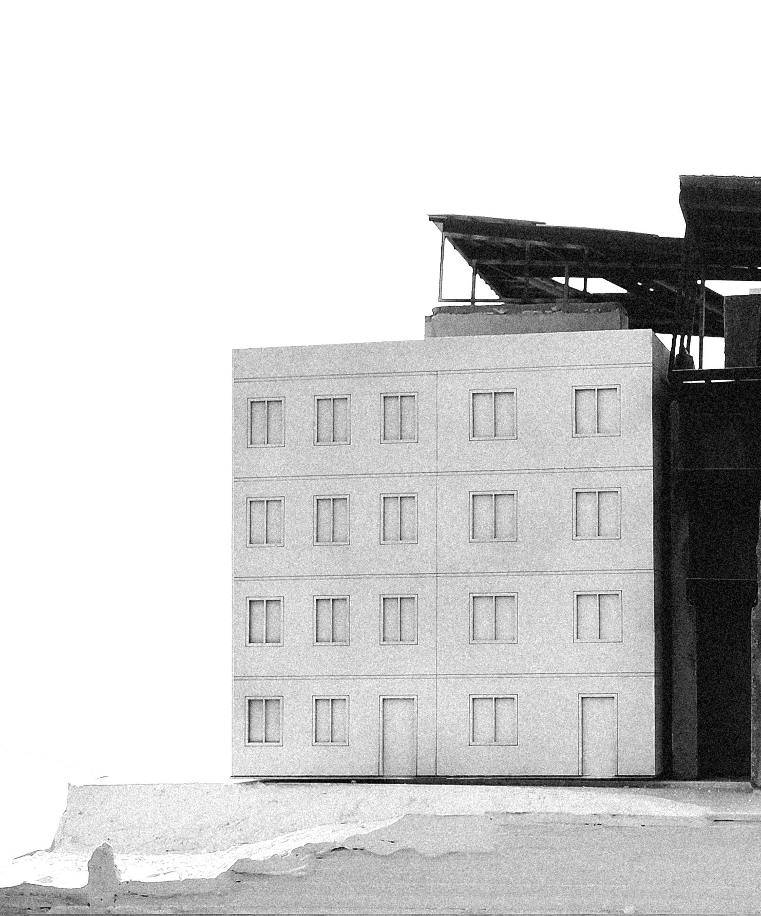
Growing in brokencourtyard
104 Phase - 3
105 Situating + Adapting
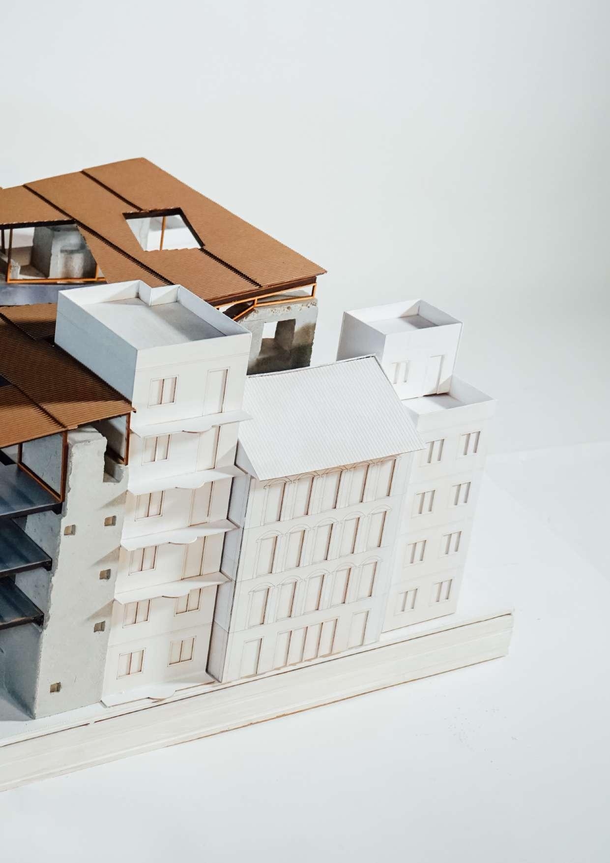
Physical Model
Facade continue
106 Phase - 3
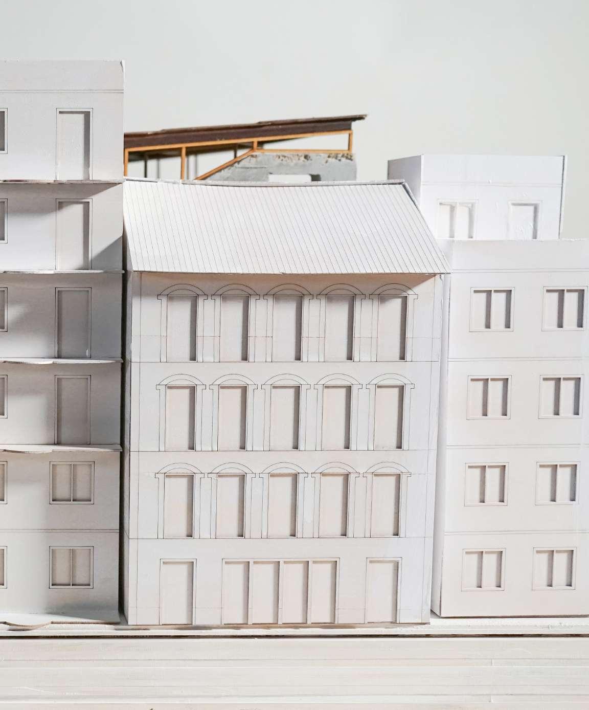
107 Situating + Adapting
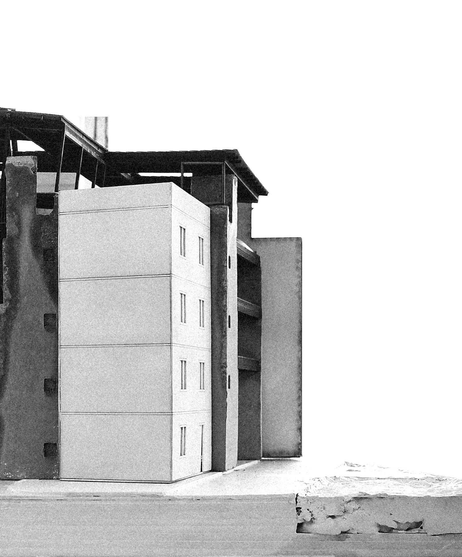
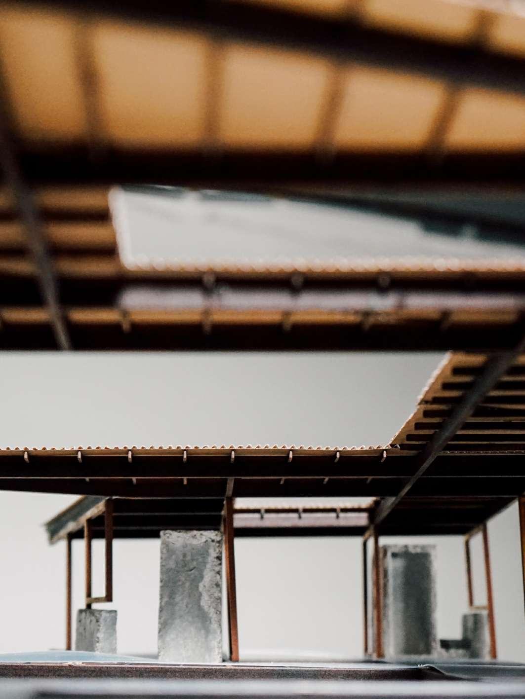
Physical Model
“Detached” Roof
108 Phase - 3
109 Situating + Adapting
Physical Model
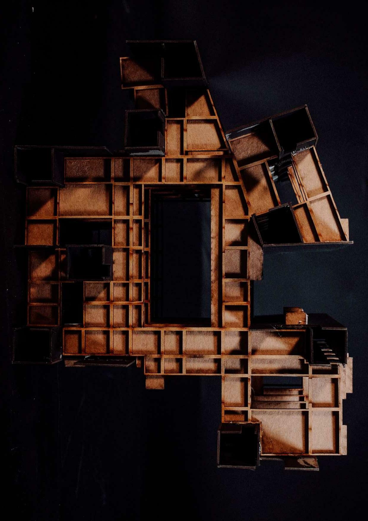
Roof Level
110 Phase - 3
111 Situating + Adapting
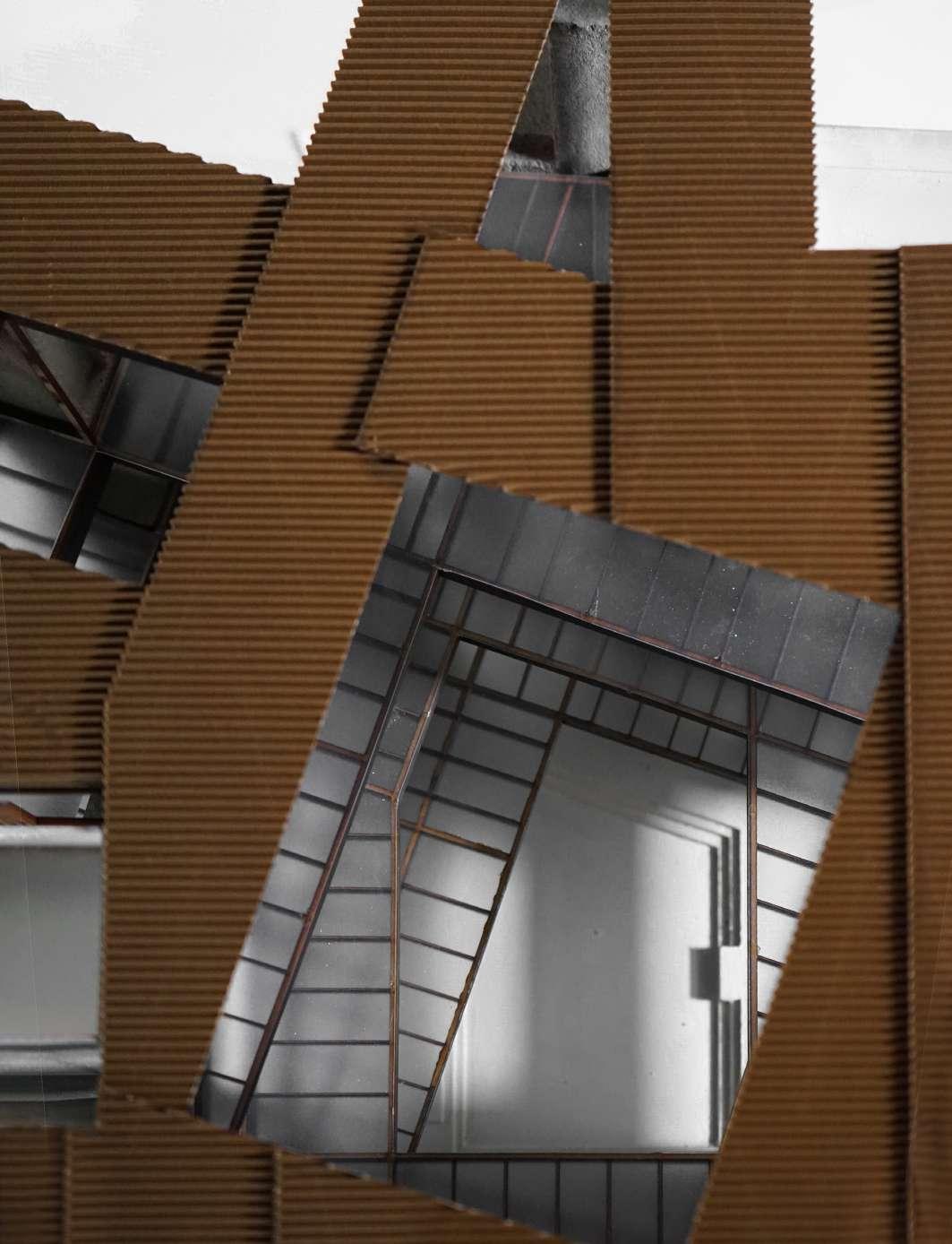
Physical Model
Courtyard overlapping
112 Phase - 3
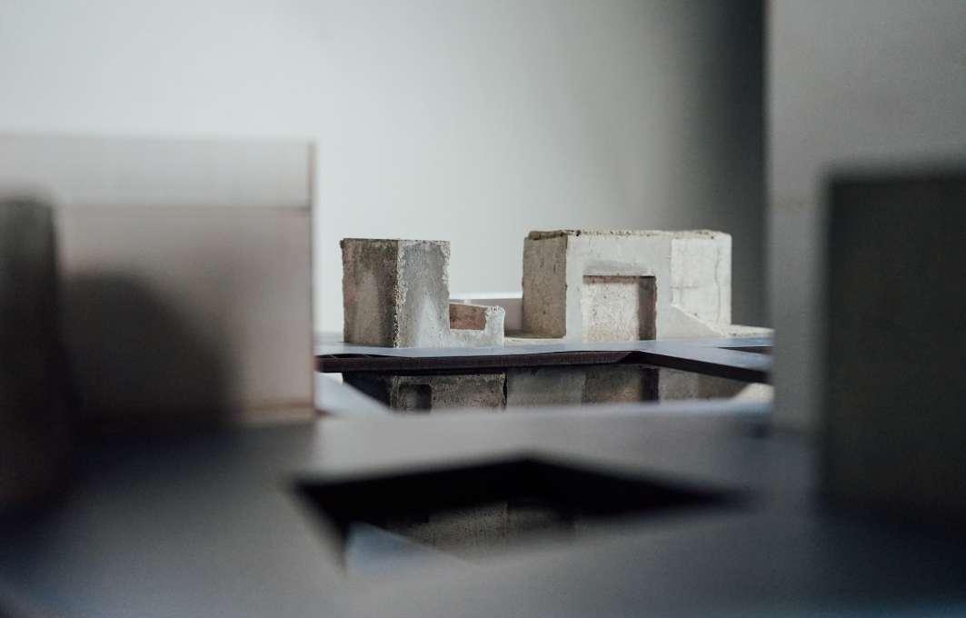
113 Situating + Adapting
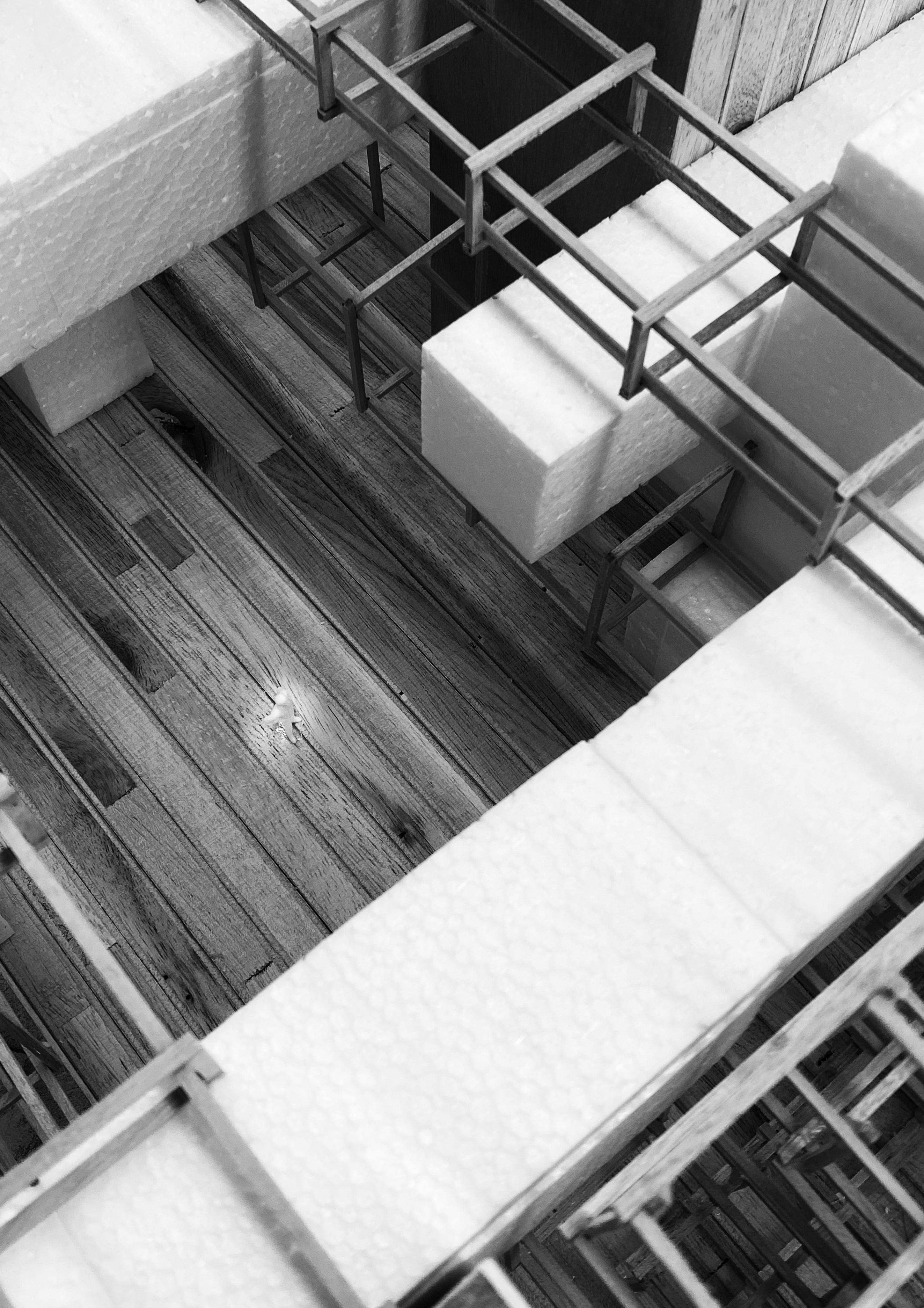
Physical Model
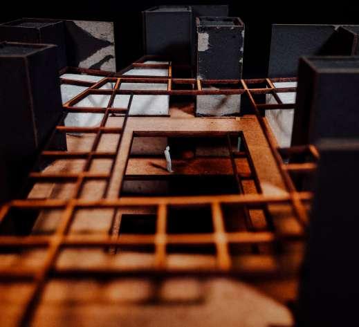
Central Courtyard Bird’s View
114 Phase - 3
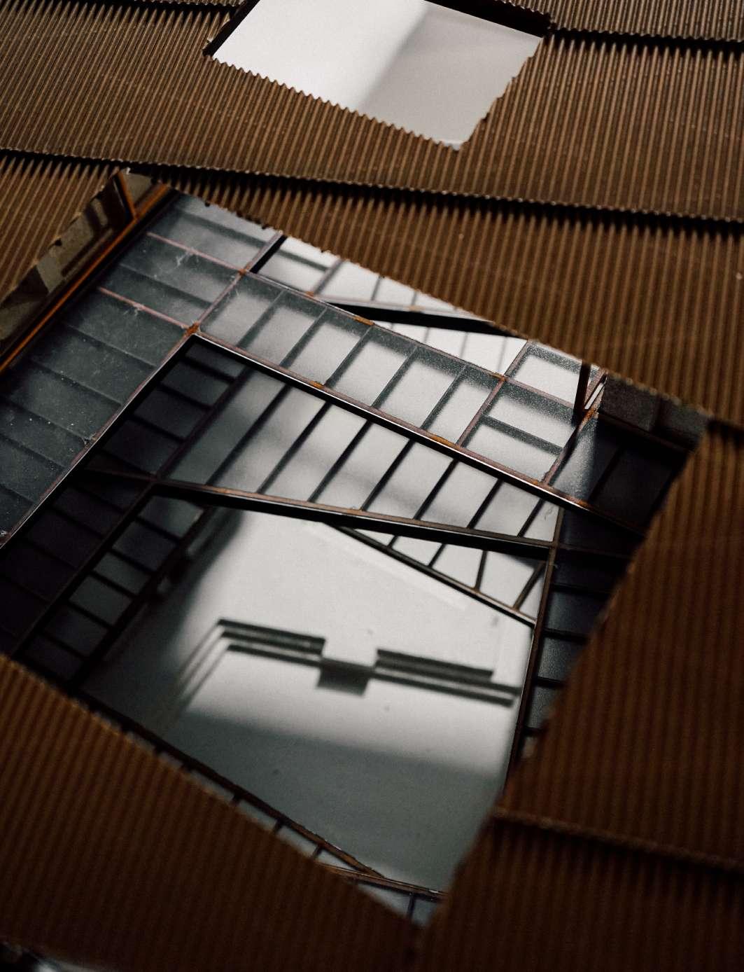
115 Situating + Adapting
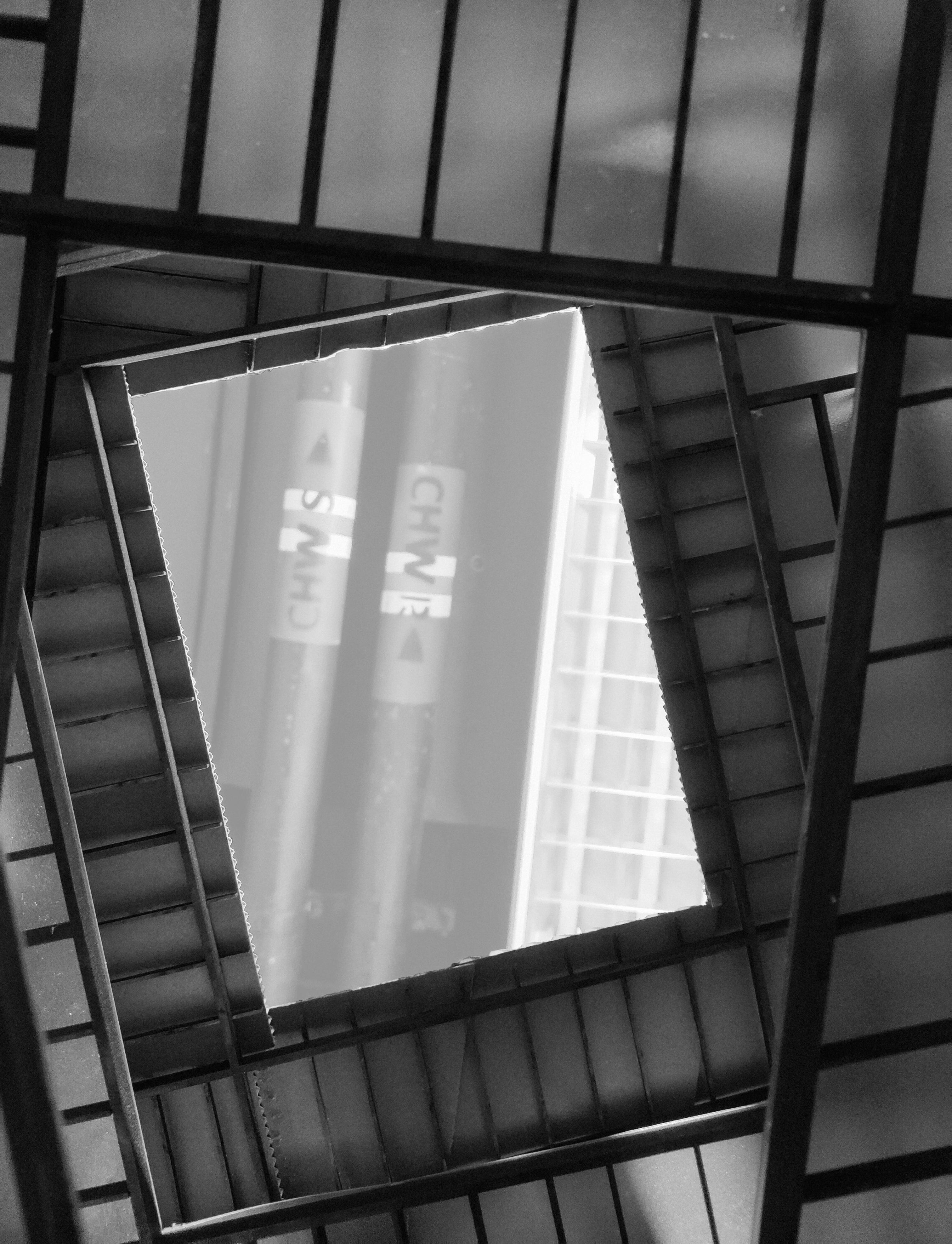
Physical Model
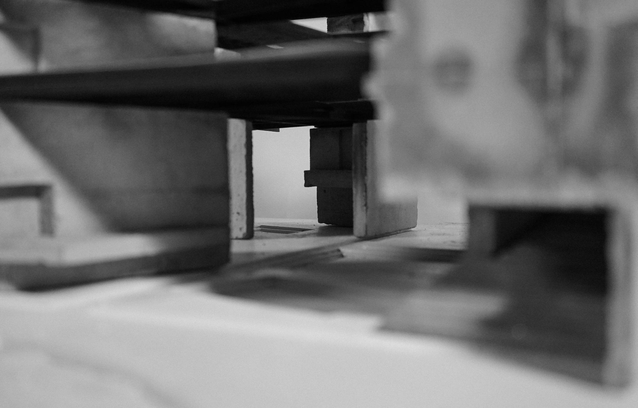
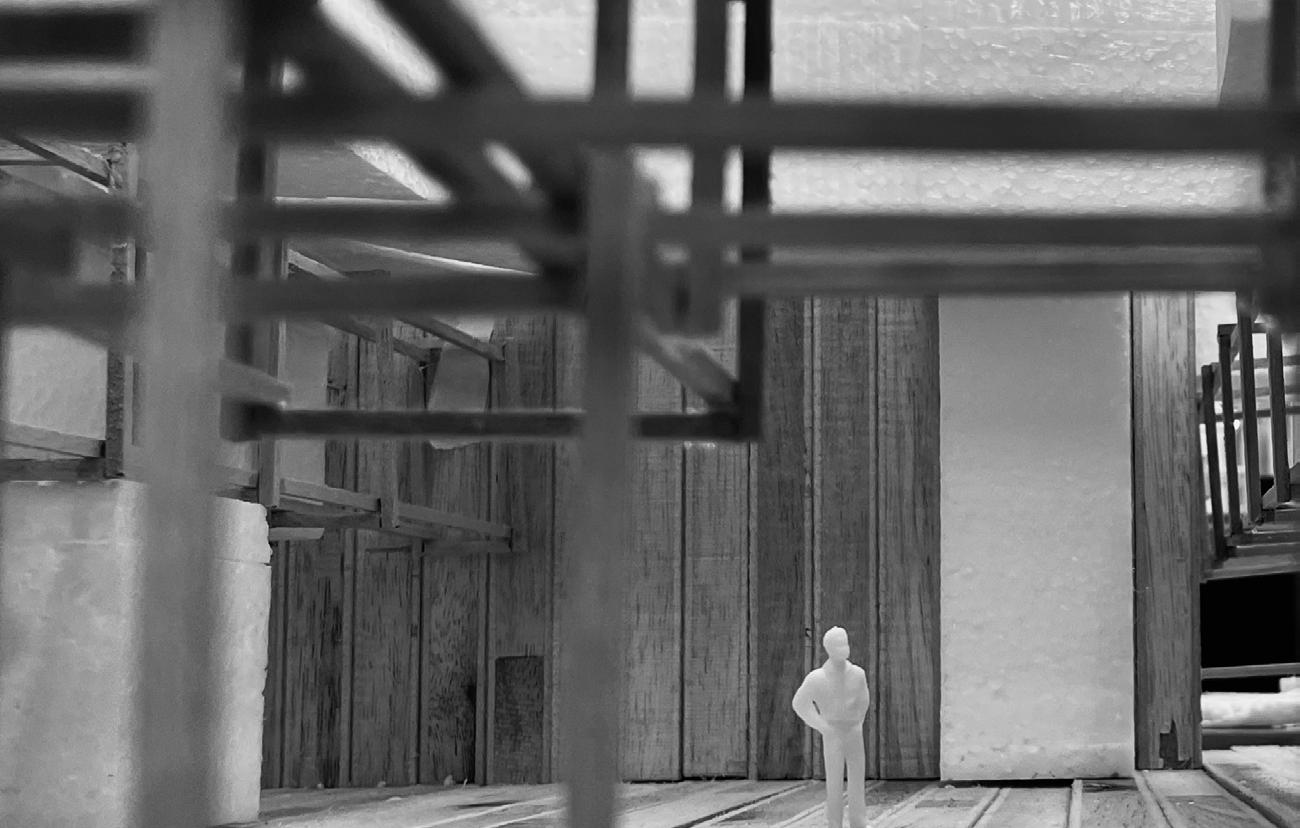
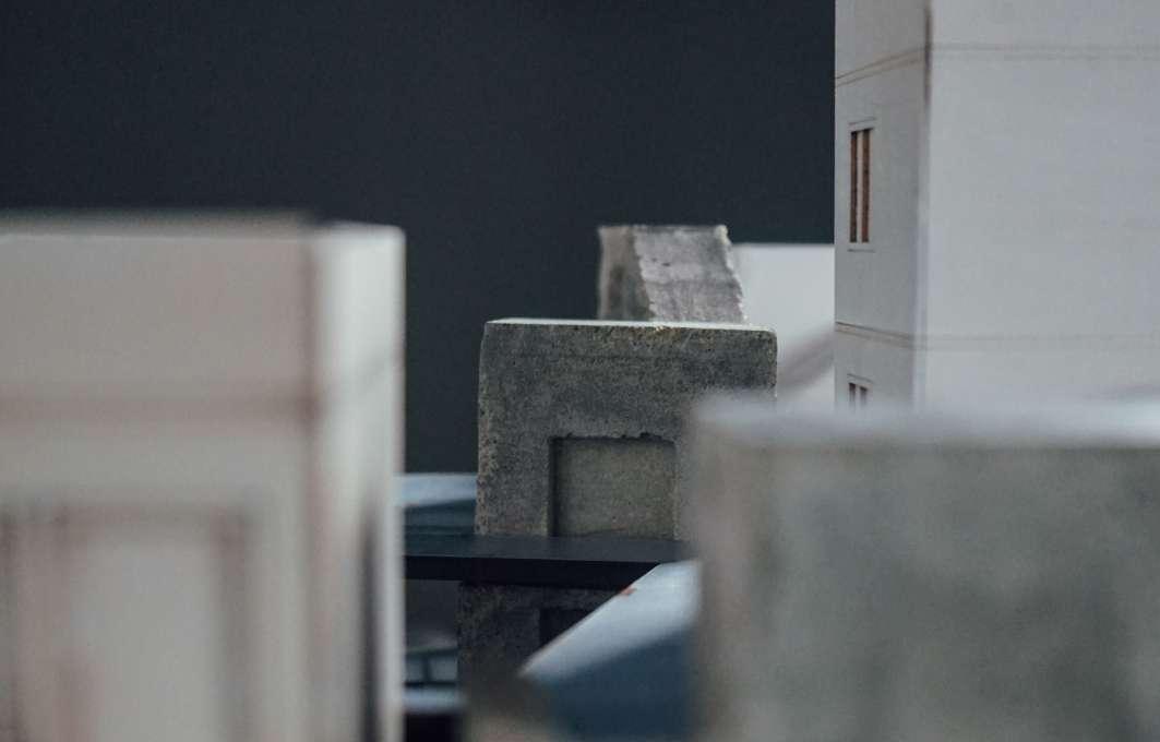
Look through the courtyard - GF
116 Phase - 3
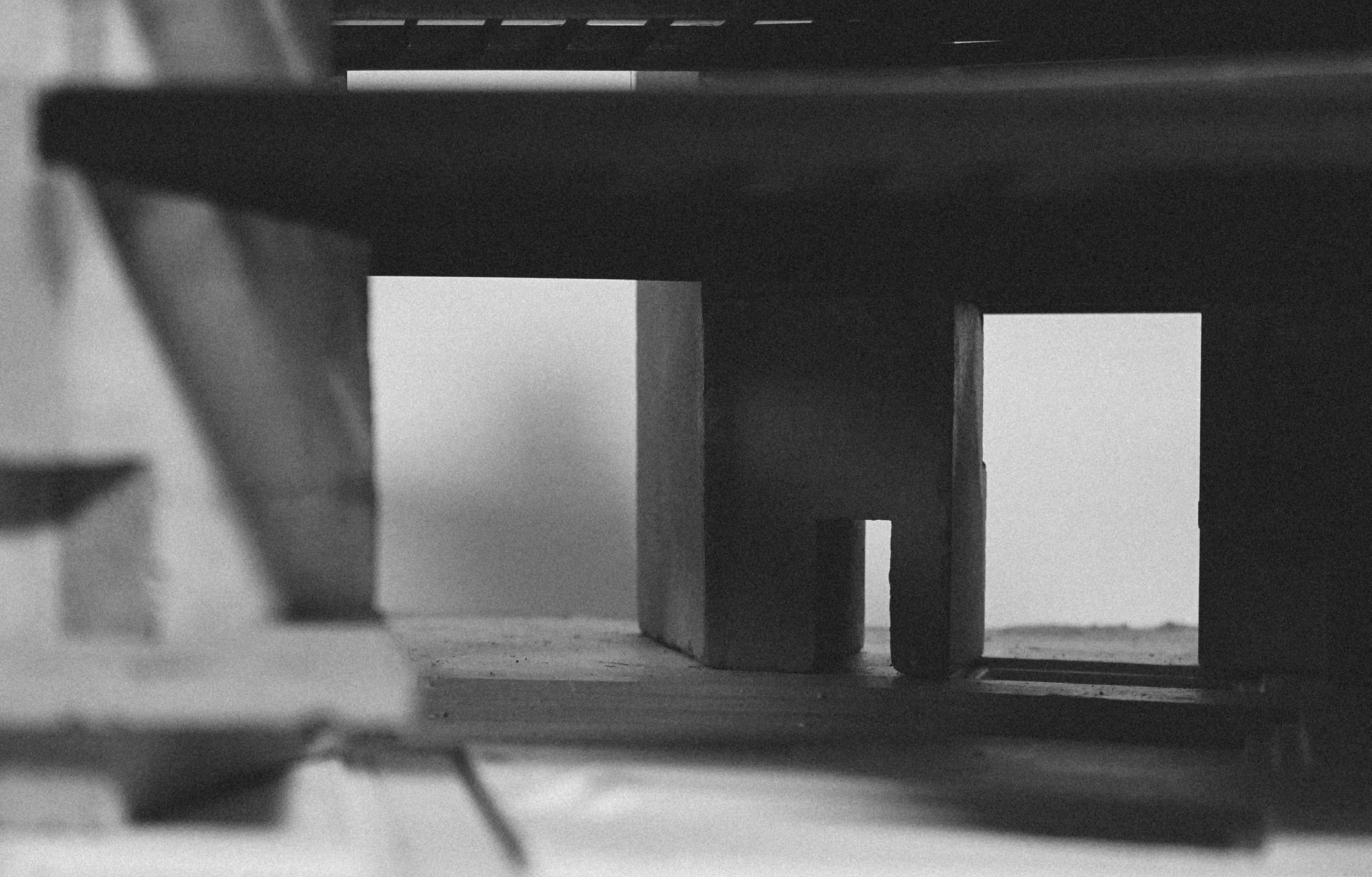
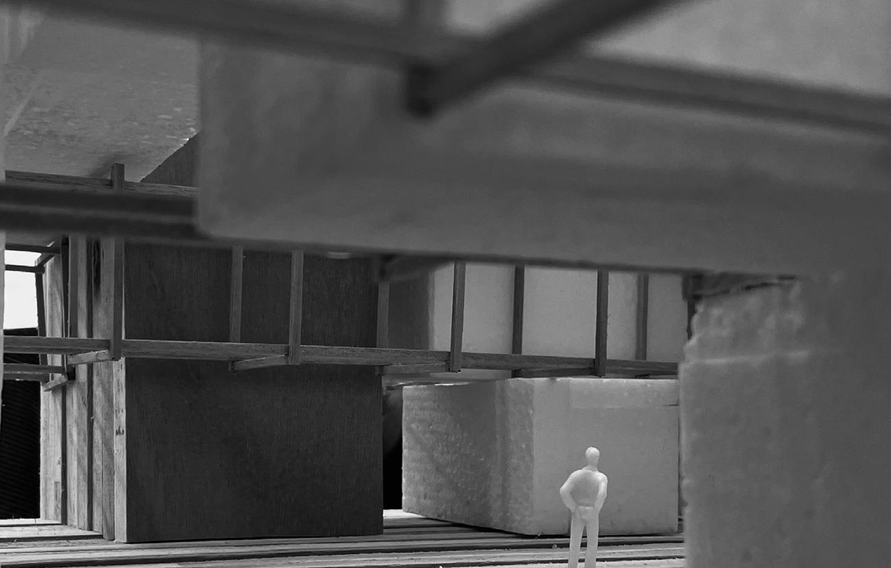
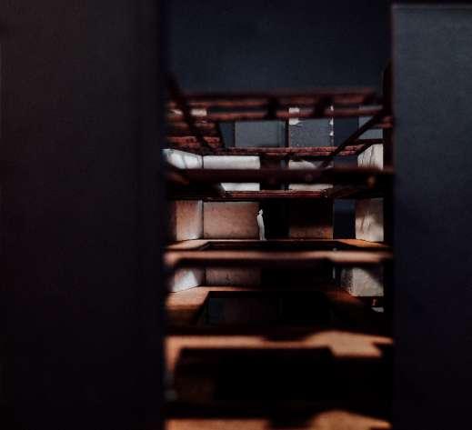
117 Situating + Adapting
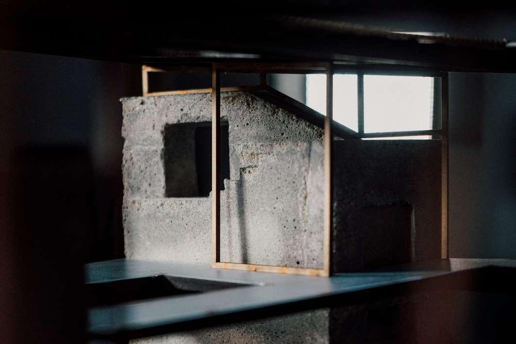
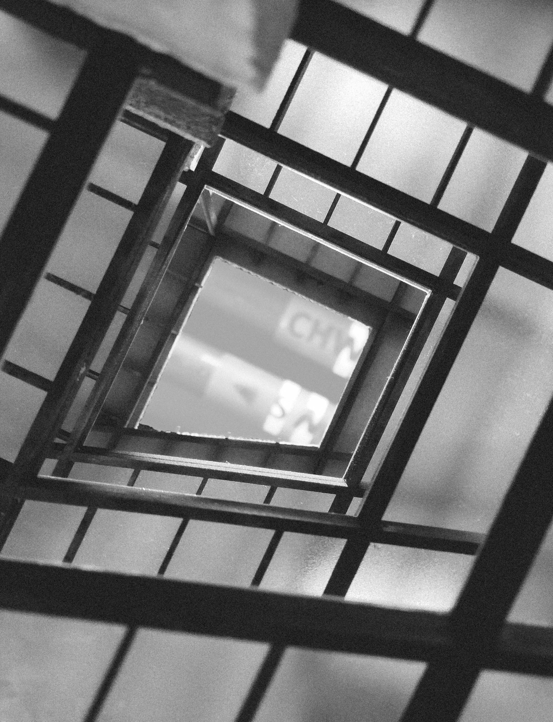
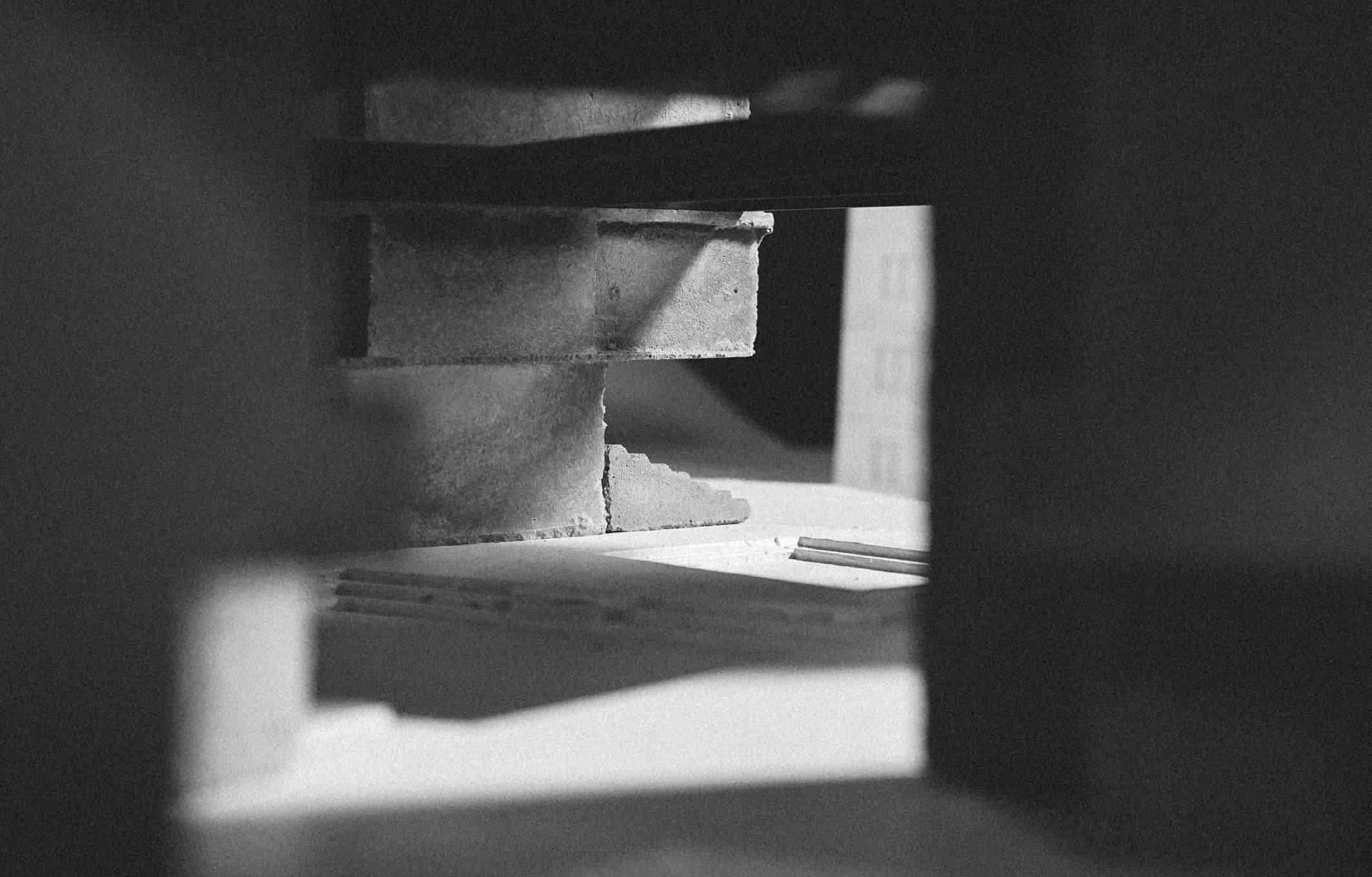
Physical Model
Look through the courtyard
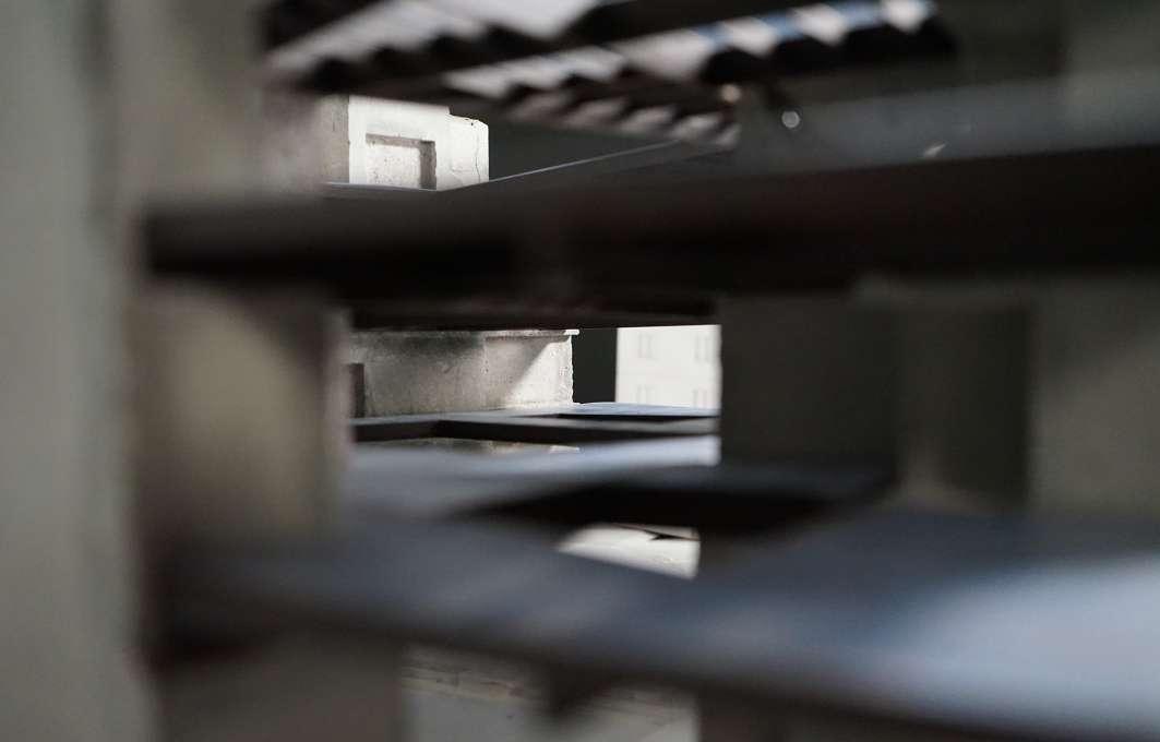
118 Phase - 3
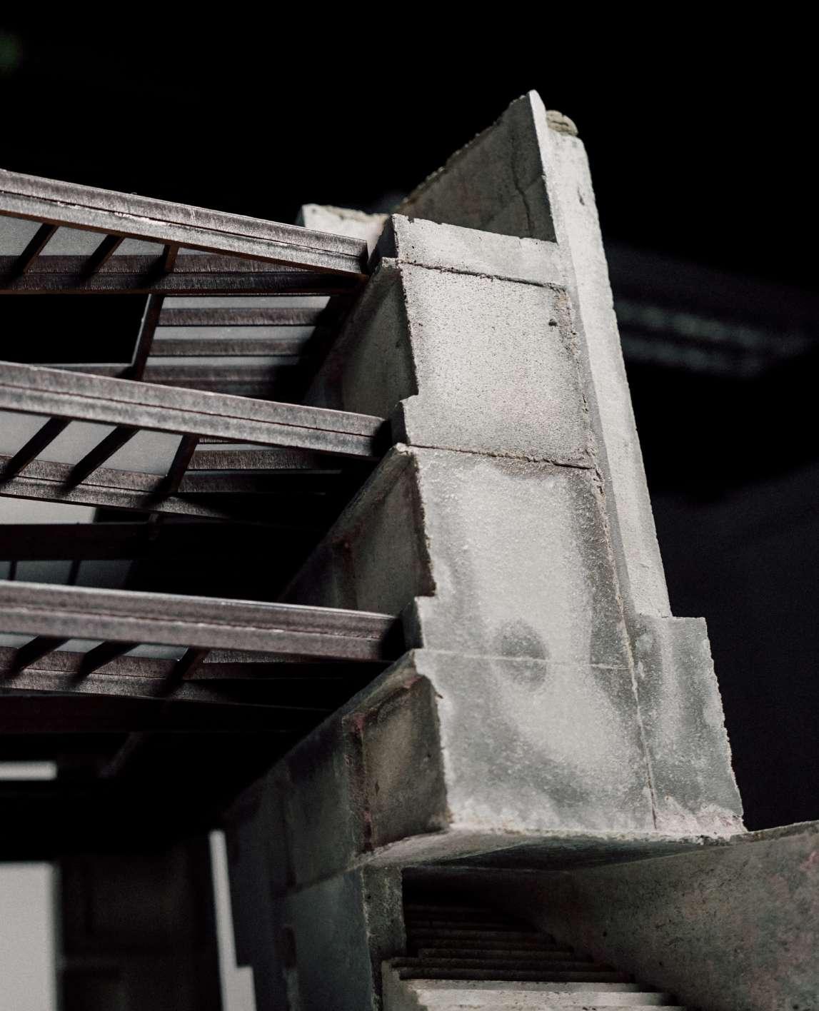
Physical Model
“Pop out” Core
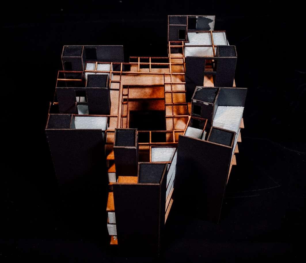
120 Phase - 3
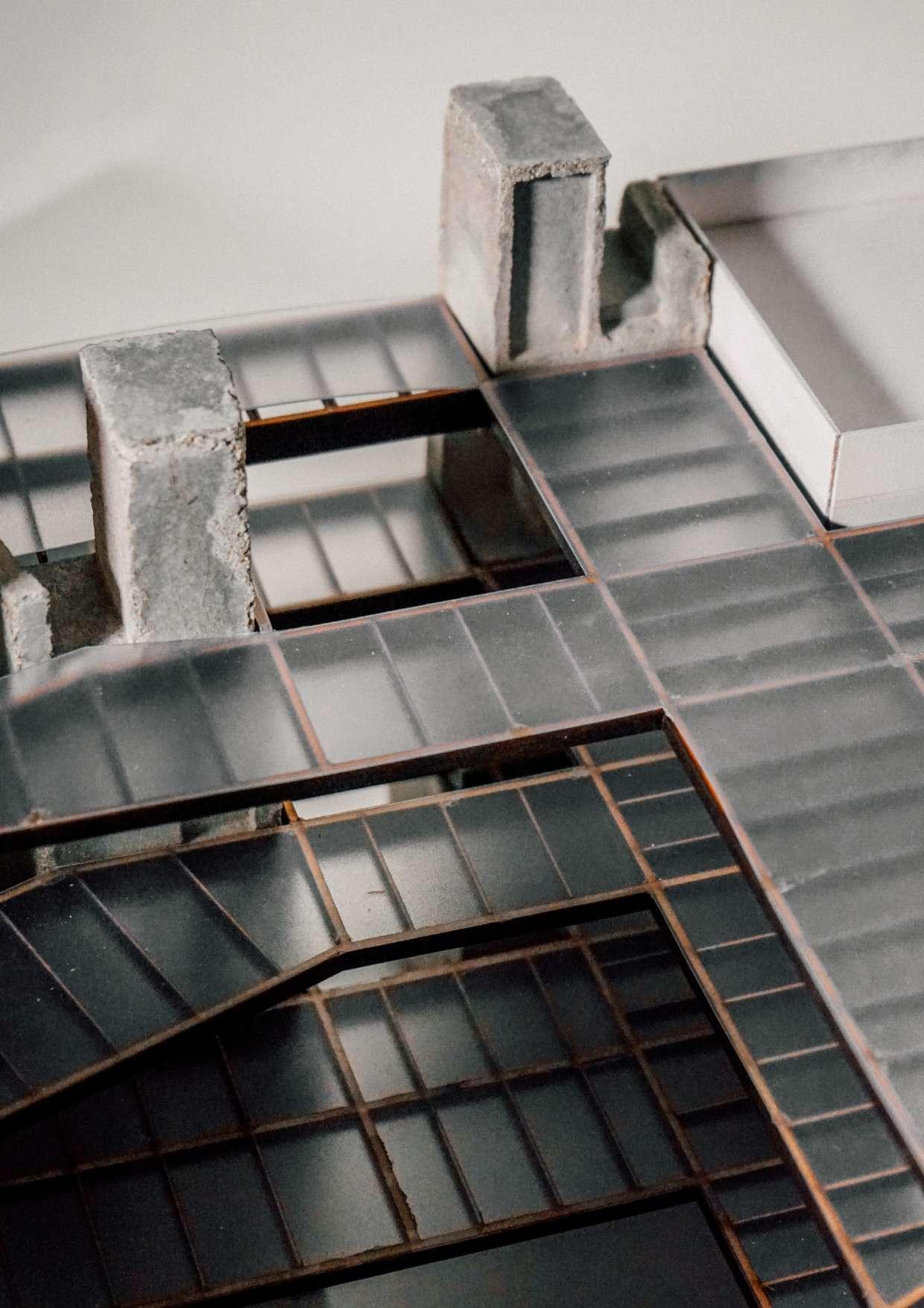
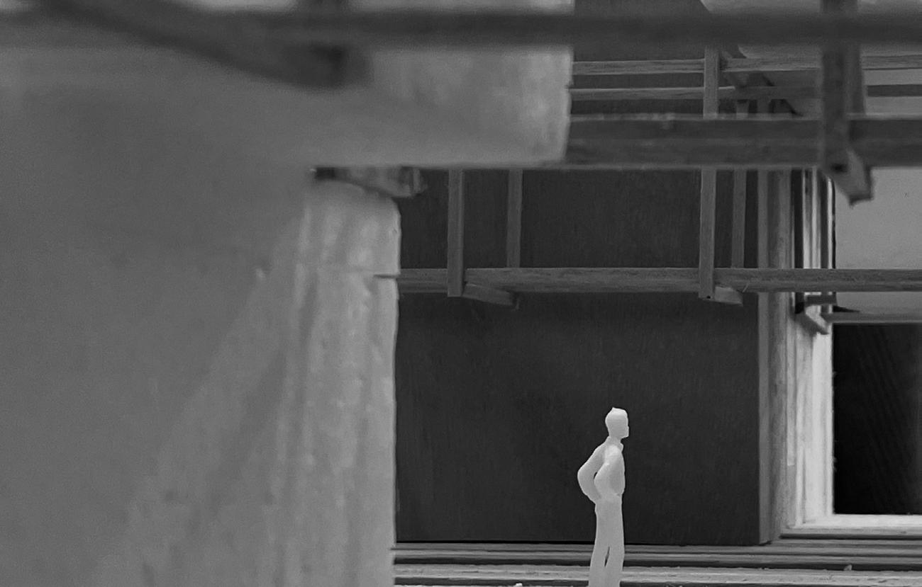
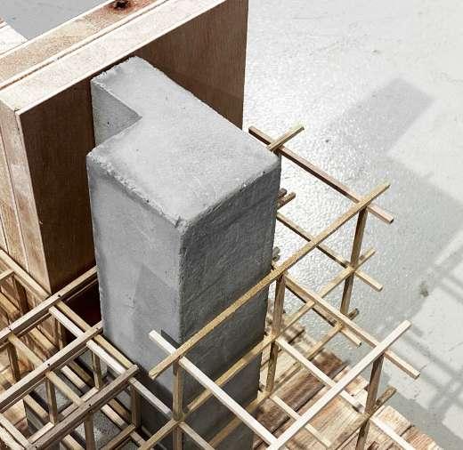
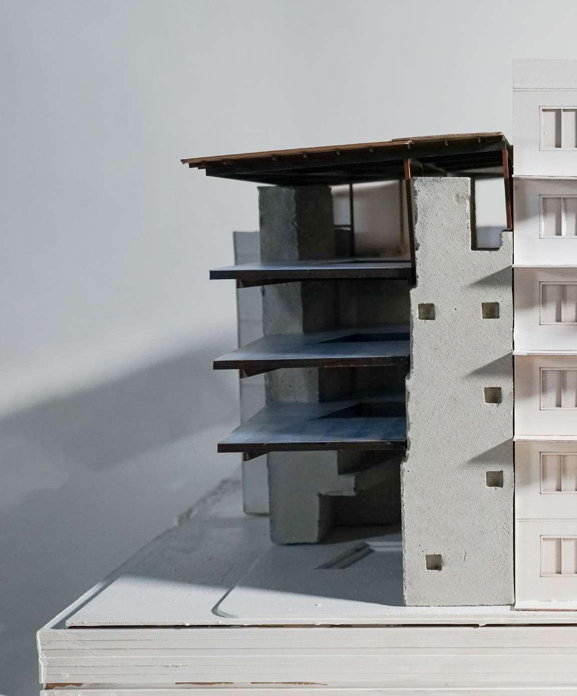
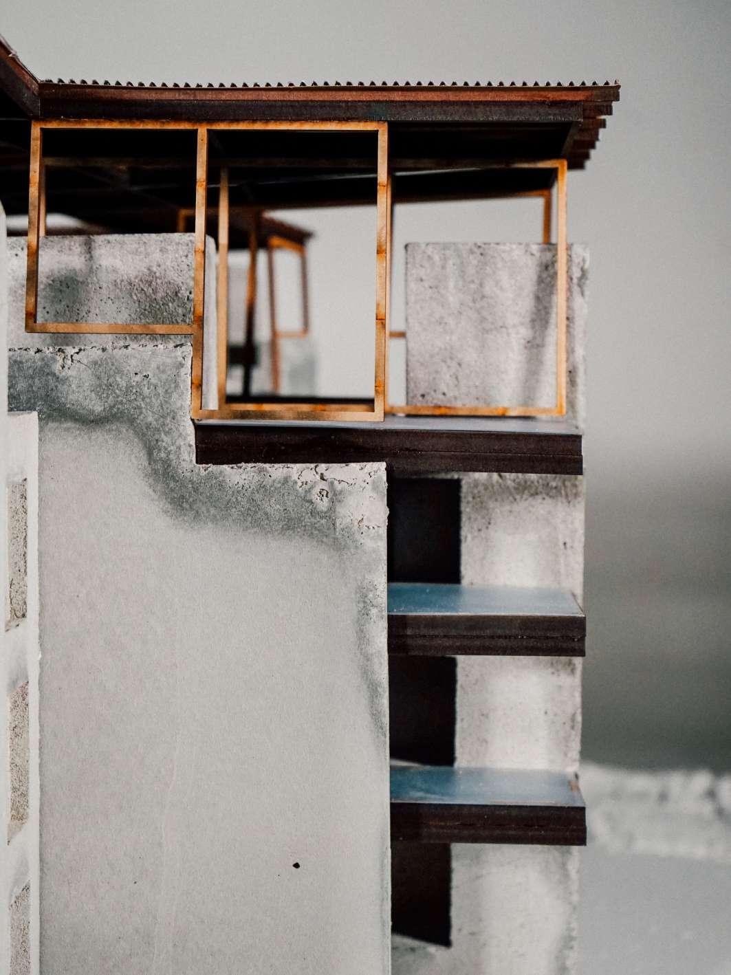
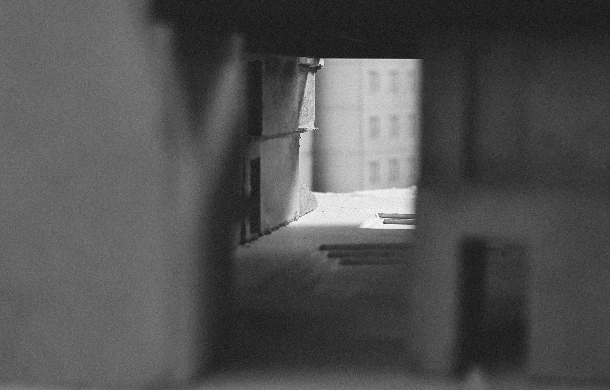
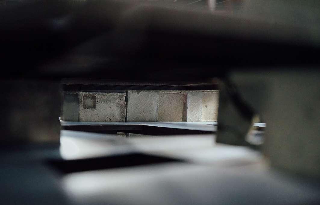
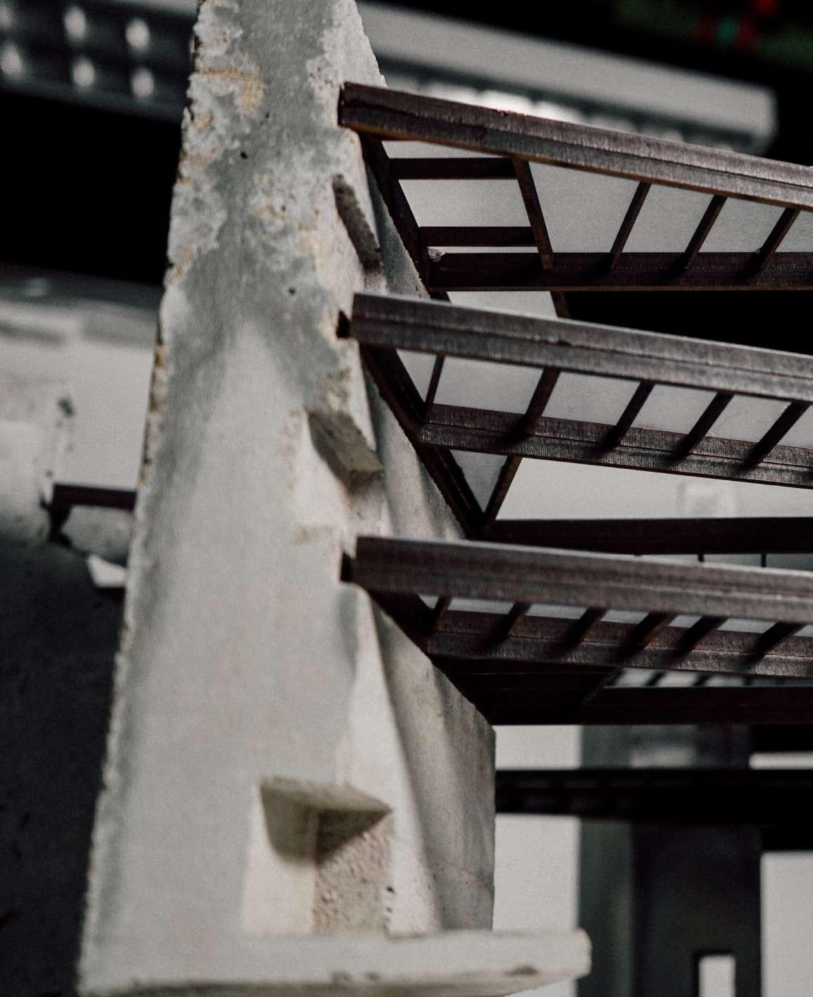
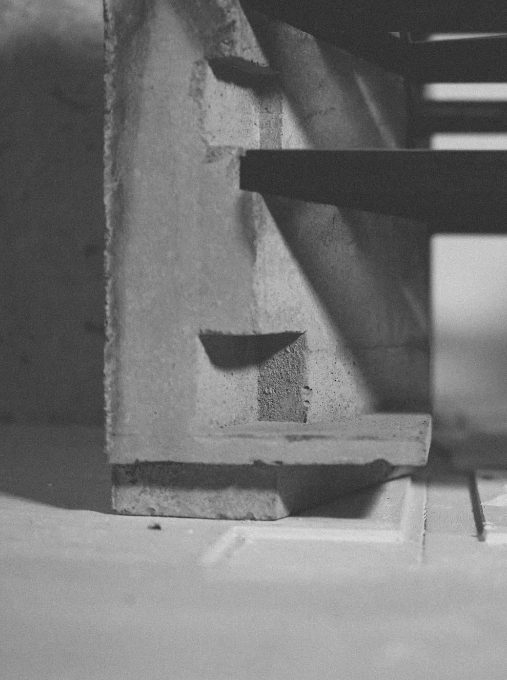
Physical Model
Frame suspended by cores
122 Phase - 3
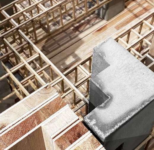
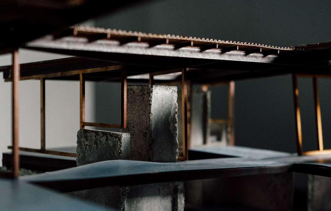
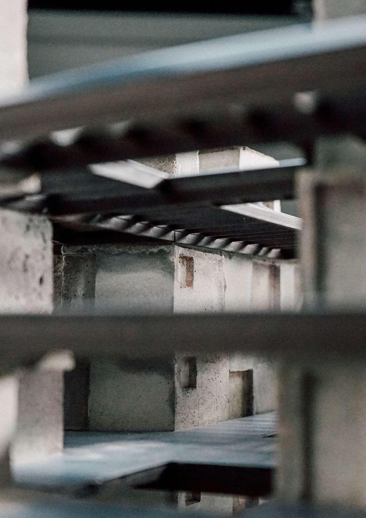
Physical Model
Frame suspended by cores
124 Phase - 3
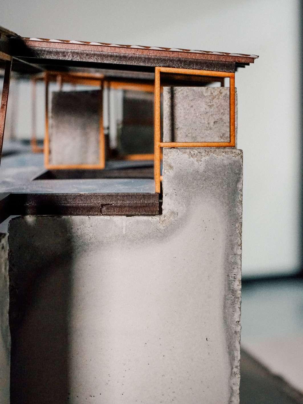
125 Situating + Adapting
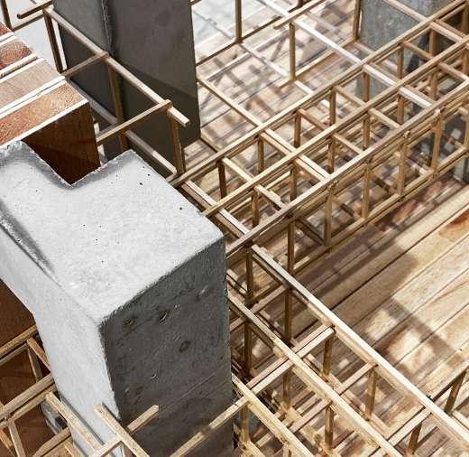
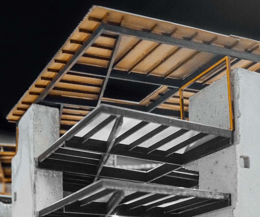
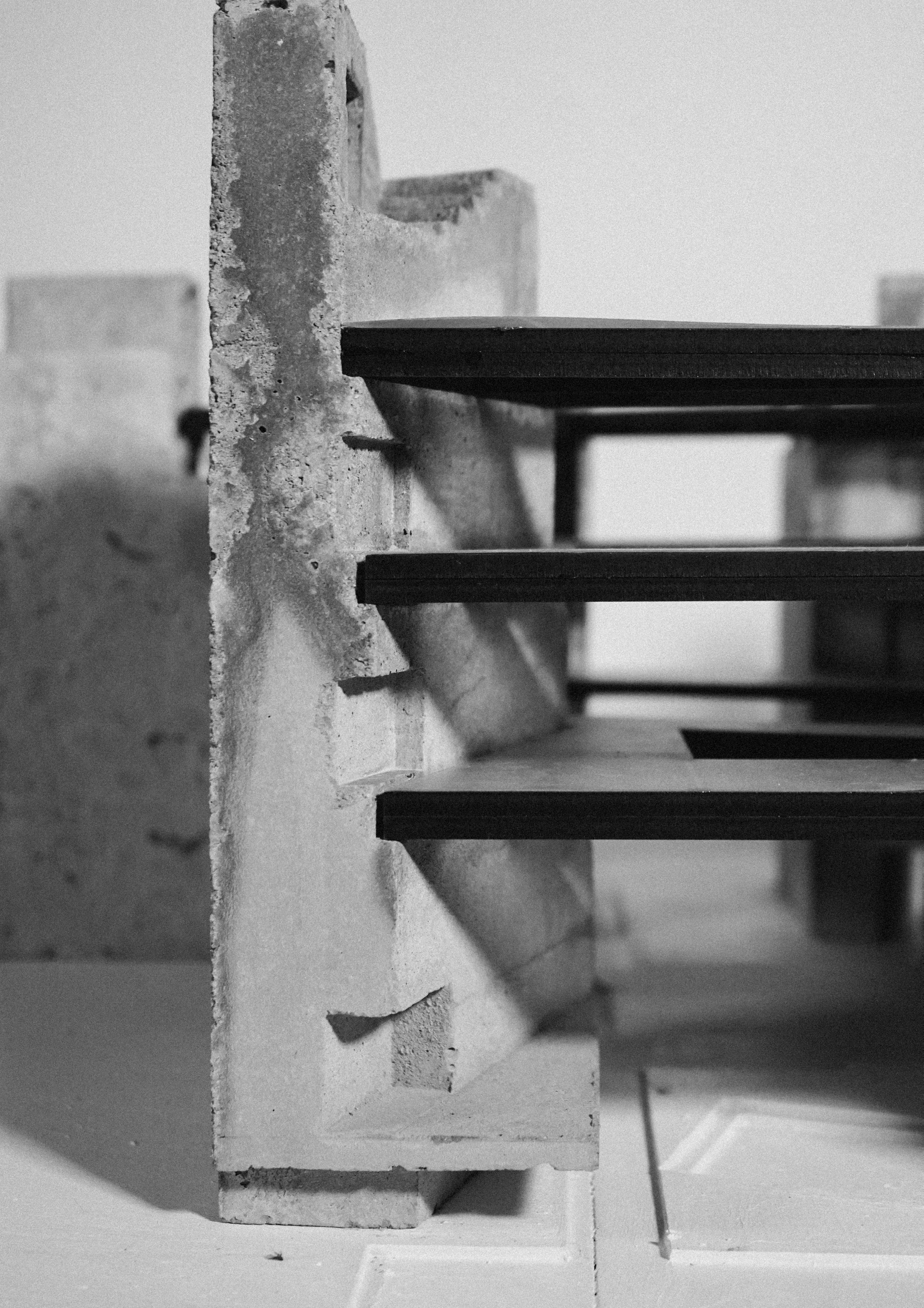
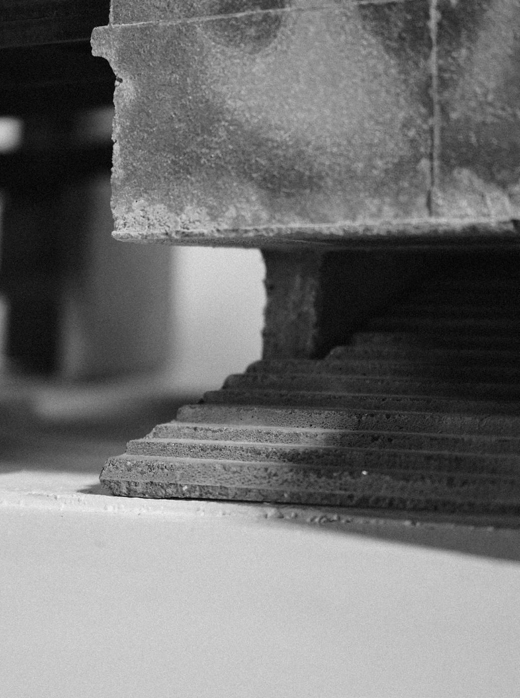
Physical Model
Detail
126 Phase - 3
NEGOTIATED GROUNDS: Generative Prototypes
WU Changrong 3035894216
ARCH7081 Design 11 / MArch Studio Semester 1 2021-2022 Joshua Bolchover + Kent Mundle / Donn Holohan + Jersey Poon The University of Hong Kong / Department of Architecture
