4 minute read
How to Accommodate Misplaced Shearwall Anchorage
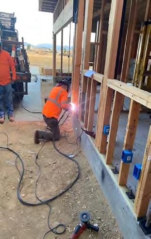
For several years, the Simpson Strong-Tie Strong-Wall® research and development team has kicked around the idea of developing an “adapter” that would allow for field substitutions or accommodate misplaced Strong-Wall anchorage.
The Strong-Wall WSWH high-strength wood shearwall uses 1”-diameter anchor bolts, and our SSW Steel Strong-Wall® installs with either ¾”- or 1”-diameter anchor bolts — depending on the model. Additionally, Simpson Strong-Tie Strong-Wall shearwalls also feature different on-center spacings for the anchor bolts across some like-width models. This makes an “easy substitution” nearly impossible.
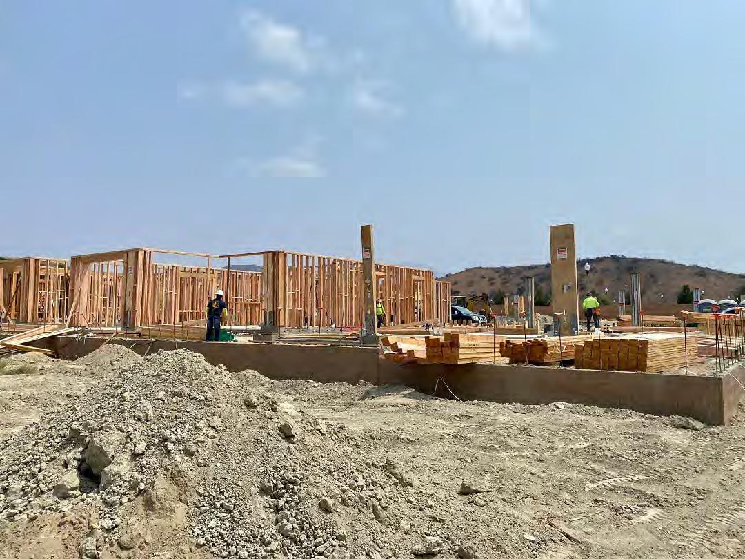
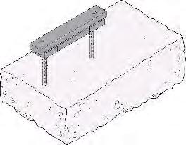
Aside from jobsite conversions, the other area where the adapter provides value is in cases where the anchor bolts haven’t been correctly placed in the field and the concrete has already been poured. This is often the case when an anchor bolt template is not used. Historically, our only option has involved costly concrete demolition and trying again with a template or drilling through thick concrete members and pouring new foundations below the existing.
Simpson Strong-Tie Engineering Supervisors Caleb Knudson and Rachel Holland spearheaded the solution to this challenge by working together with our engineering team to develop an adapter. Below is a step-by-step description of how the adapter works.
Step 1 — The solution consists of two 1¼”-thick by 3½”-square steel plates with tapped holes that thread onto the anchor bolts that are already set in concrete. The fact that these plates are square allows them to be tightened in quarter-turn increments so that they are both tight to the concrete and the plate edges are in the same plane as the 2×4 framed wall. They may also accommodate any anchor bolt spacing associated witha different manufacturer’s wall or Simpson Strong-Tie StrongWall shearwalls. The existing anchor bolts are then trimmed flush with the top of the steel plates.
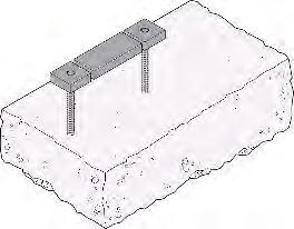
Step 2 — A spacer plate is placed between the two square steel plates. This 1¼”-thick spacer plate is pulling double-duty by providing additional concrete bearing capacity for the entire assembly and stiffening up the continuous plate above it (which is detailed in Step 3).
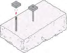
Step 3 — A continuous plate spanning the square plate washers and spacer plate provides a bearing surface and connection point for the SSW or WSWH. It features two ¾”- or 1”-diameter tapped holes in the correct location to allow for Strong-Wall panel installation.
Step 4 — The final step before installing the Strong-Wall anchor bolts is to connect the pieces together. The connection is made in the field by a certified welder with simple fillet welds from the continuous steel plate to the plates below. This provides a strong and stiff surface for the SSW or WSWH to be installed onto.
Step 5 — Custom length anchor rods are then threaded into the continuous upper plate to allow for Strong-Wall attachment. Since we need to reduce the height of the Strong-Wall panel by the height of the adapter assembly, the preferred solution is the WSWH high-strength wood shearwall. This panel is made of a wood-based material which can be trimmed in the field with a skill-saw — one of its most popular features. The same cannot be done with the SSW Steel Strong-Wall® shearwall.
And there you have it, a solution that has been incredibly well-received in the field — especially when the alternatives are to bring out a jack-hammer or spend two full days drilling the required holes into the existing concrete foundation so that underpinning can take place. And for both of these typical fixes, new concrete must also be poured. Instead, our adapter allows you to fix your anchorage without breaking your schedule.
The article, How to Accommodate Misplaced Shearwall Anchorage, appeared first on Simpson Strong-Tie Structural Engineering Blog. To sign-up to receive the Engineering Blog in your inbox, go to seblog.strongtie.com/subscribe

Copyright © 2023 Simpson Strong-Tie Company Inc. All Rights Reserved
Wescana Jack Press & Table

35 Ton Hydraulic Press with 14" Wide Platen Press Roof or Floor Truss (4" Maximum Opening)
Steel Frame Table with 1/4" Steel & 1" Plastic Top Slotted Jigging at 12" Centers | Joystick Control
7.5 HP / 3 Phase (208/230/460/575 Volt)
6' x 25' Table & 8' x 25' Table Available
800-382-0329 | www.wasserman-associates.com
Door } Stair } Window Machines
BAM Door Loader, Model 2001
BAM “Ovation”
Door Machining Center (DMC)
New Builders Automation Machinery
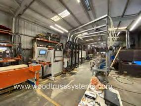
“Ovation” series, door machining center (DMC). Fully programmable, two-stage door machine featuring (27) axes of operation. Can be specified with either two or four front machining heads. Machine is side-eject, direct-drive with helical gear racks and gear protection from dust. The door loader is driven by an absolute encoder; no stepping motors, belts or exposed ball screws are used.
More information Click Here
Price based on configuration
Wood Tech Systems
765-751-9990 www.woodtechsystems.com
RUVO MODEL 1300 DOUBLE END DOOR TRIM SAW
$4,250 FOB PA
Wasserman & Associates 800-382-0329 www.wasserman-associates.com
Dotul Door Stop Stitcher
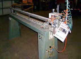
Click Here for details
$4,900 NOW $3,600 FOB GA
Wasserman & Associates

800-382-0329 www.wasserman-associates.com
Builders Automation Machinery (BAM) door loader, model 2001. Allows you to stack door slabs horizontally and feeds them into a horizontal door machine like the BAM model 996E-TS. Mechanically adjusts door stack height vertically as slabs are fed into machine. Clamp automatically adjusts to type and size of door slab: steel, solid-core or hollowcore, from 6-ft to 8-ft heights. Electronic, programmed controller manages the loading process. Loader positions the door stacks adjacent to the door machine infeed to save effort of the operator. Pneumatic motor and heavy-duty drive train provide dependable continuous use. Cycle time approximately (30) seconds per loaded door slab.
Footprint approx. 10′ x 10′ x 11′. Weight 2,000 lbs. 120 volt, 1 phase, 15 Amp electrical required. 120 PSI at 20 CFM (1/2″ ID line min.) air required.
Price Based on Configuration
The truss industry relies on 3rd party quality assurance services to provide random visits to review the plants Quality Assurance program along with their operations. If your plant needs to comply with the IRC, IBC and to those who depend on solid, experienced QA expertise, we ask you to consider selecting Timber Products Inspection, Inc. (TP) as your choice for 3rd party inspections.

Proudly serving the forest products industry for over 50 years, TP brings the expertise you need to ensure your business is successful. As a responsible partner, TP delivers to clients, employees, and the industries we serve the confidence to drive value through the effective use of our diverse professional team.

TP would like to welcome the following authorized agents to our inspection team, each of whom have many years of experience in the truss industry!
• Al Coffman
• Jean Hart
• Curt Holler
• Chuck Ray
• Glenn Traylor
• Elliot Wilson https://www.tpinspection.com/ https://www.tpinspection.com/auditing-services/truss
If you have questions about how you can make this selection, please contact your authorized agent above or Glenn Traylor at 919-280-5905 or trusguy@gmail.com.


