Design Portfolio
Skills & Goals Statement
I am interested in how people engage with the built environment—and how I can enrich that engagement as both an architect and a builder. I’m a lifelong learner, treehugger, and tool lover. Whether it’s software, saws, chisels, or shovels, I use them all—and respect the knowledge each one demands. My goal is to keep expanding how I think, design, and build. I want to apply my skills in pursuit of licensure in both architecture and construction supervision. I believe the most universal tool is the collective experience of a strong team, brought to bear at the right time and in the right place. I hope to join yours.
Transdisciplinary Studio: Art Gallery
Orientation Diagrams
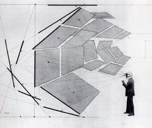
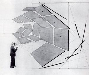
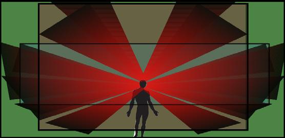
My first studio class at the BAC brought architecture students of architecture together with students of interior design and landscape architecture to design a gallery for Newburty Steet where the sidewalk level connected to the second floor of the space. I was inspired by Bauhaus-era Exhibition Design and used Herbert Bayer’s ‘Fields of Vision’ diagram to analyze my final
building design. Bayer’s diagram presents his idea of an “extended field of vision,” pushing beyond the usual horizontal line of sight. I used Bayer’s diagram as a brush in Adobe Illustrator and traced paths through a section drawing (bottom of page) to show overlapping fields of vision moving along circulation paths based on plans.
Orientation Diagrams
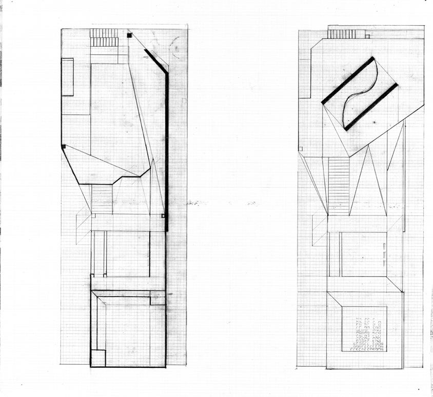
Above: top - Circulation paths for each floor; Adobe Illustrator used to diagram overlapping vision fields based on Bayer’s methodology (middle) and traced along four paths through the building (bottom) Below: top - Circulation paths digrammed over an Elevation; bottom: diagram of the vision field of a visitor walking along the ground floor path. two hand drawings from my first attempts in my Masters program are layered to show a section of the final building design and the town house behind it serves as a reminder of the architectural sclae and context of Newbury Street.


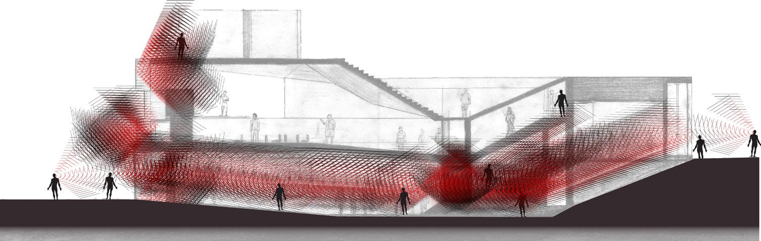

fields where the fields overlap the most were where visitors were most likely to see eachother.

L1: Pulse Room L2: Street and Sol Lewitt L3: Passage to Roof L4:Rooftop, Dan Graham
Architecture Studio 1
Ferry Terminal
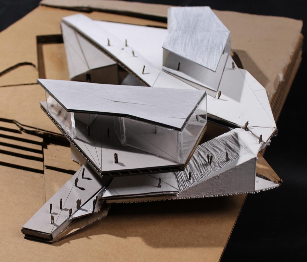
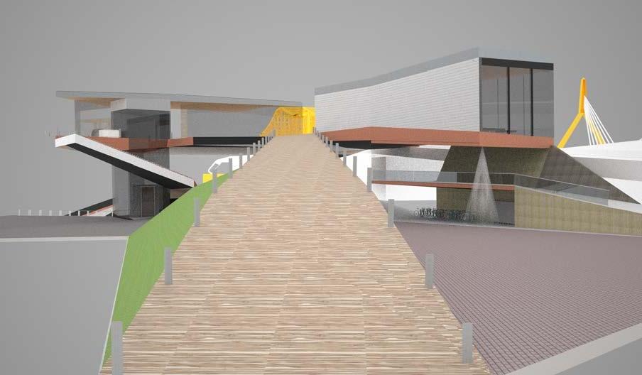
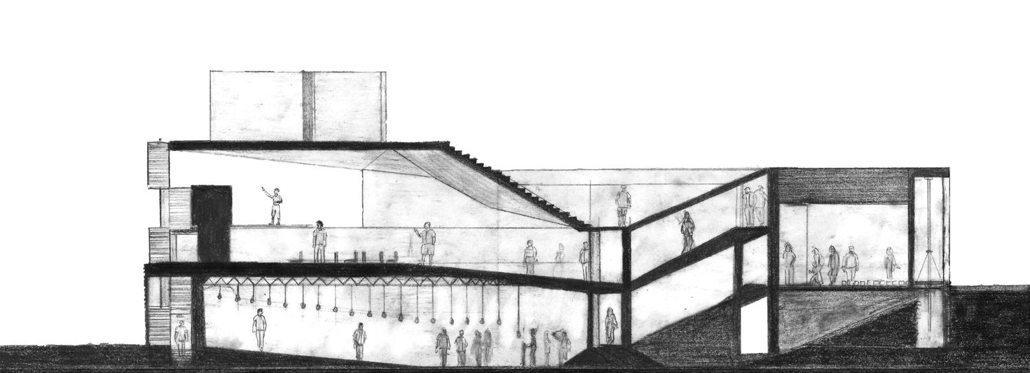
Designed in my first studio course focused on architecture, this Boston Harbor ferry terminal connects to the city by framing views of landmarks from its site at Prince Street Park. The building mimicks its surroundings and connects visitors to the site on the corner of the North Washington Street Bridge and Commercial Street by adopting a bridge-like ramp that leads from the sidewalk up to a second level with two distinct volumes: an art gallery and a restaurant.
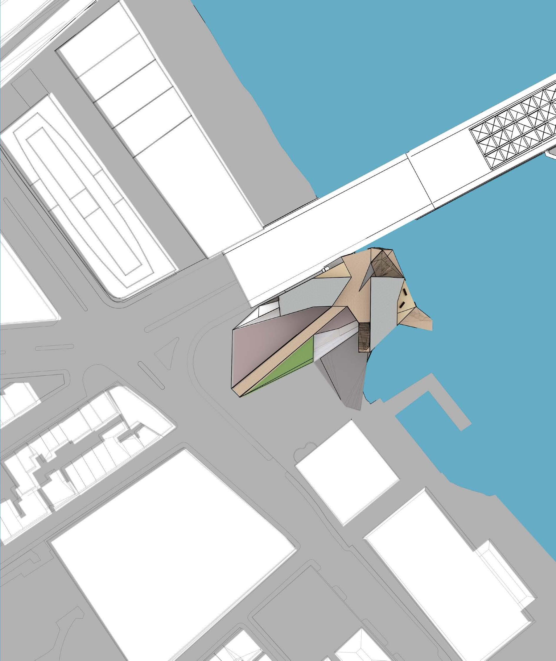

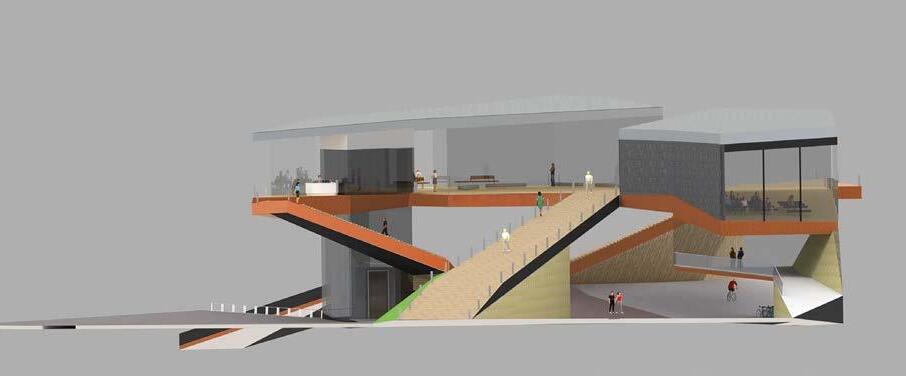
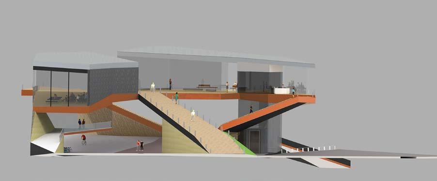
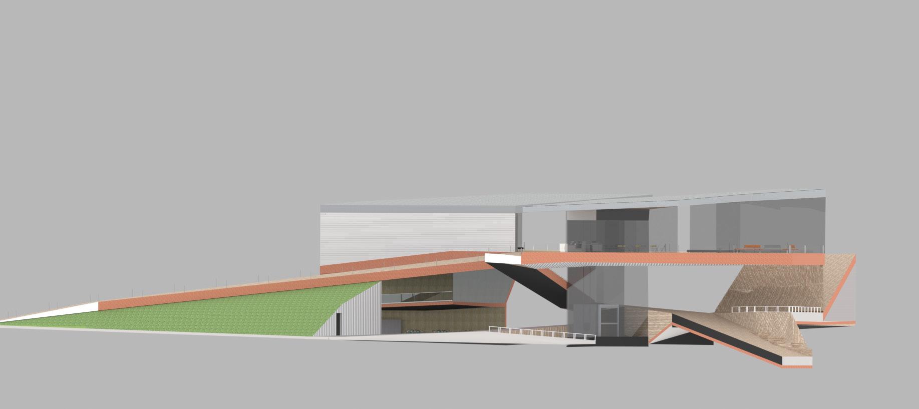
Clockwise from top left: the final model assembled from lasercut chipboard, acrylic, and 3D printed pieces derived from the digital model; a rendering shows a view taken at the foot of the ramp to show how it beckons one up with a view of the highlighted landmarks in the background, and the building itself; physical model, NW-SE elevation rendering with collaged urban context, NE-SW elevation, plan.
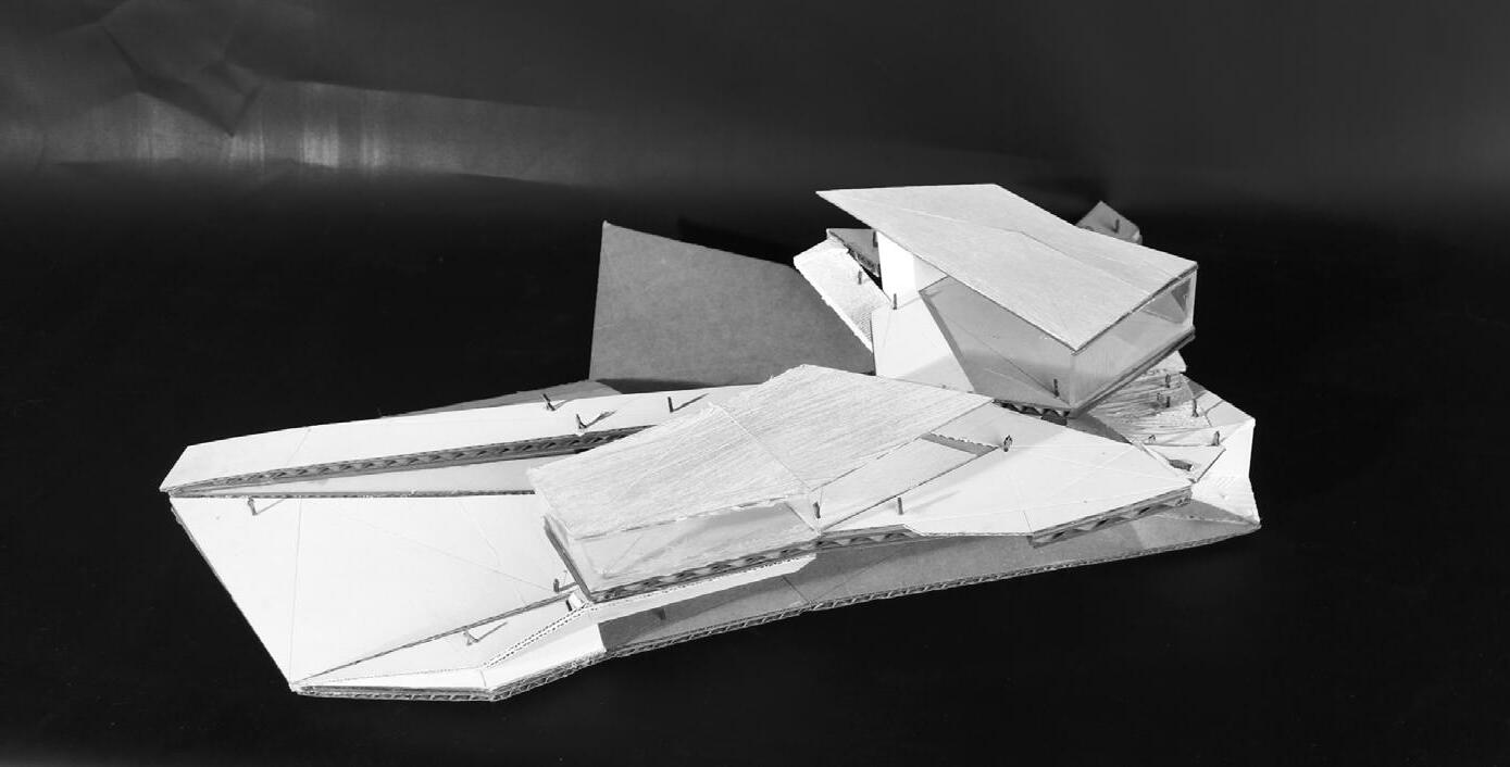
Stairways connect the ground level to the upper terrace, doubling as seating. The final model, built with laser-cut chipboard, features a roof derived from a 2D schematic plan, traced into SketchUp, modeled in 3D, and unfolded to define its geometry.
Below you can see the concept digram for the final project that presents an exploded axonometric view detailed in Adobe Illustrator to show how the walkways provide paths to guide the visitor’s vision of the city.

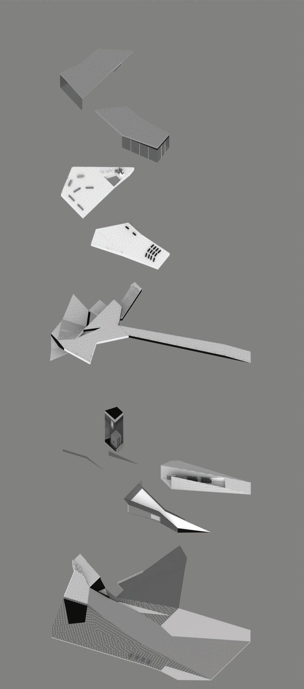


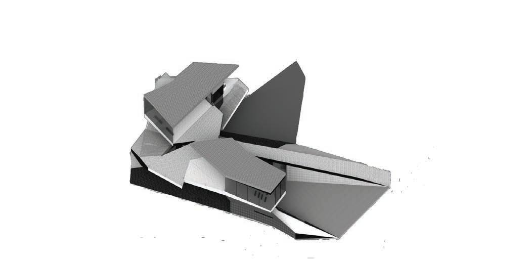
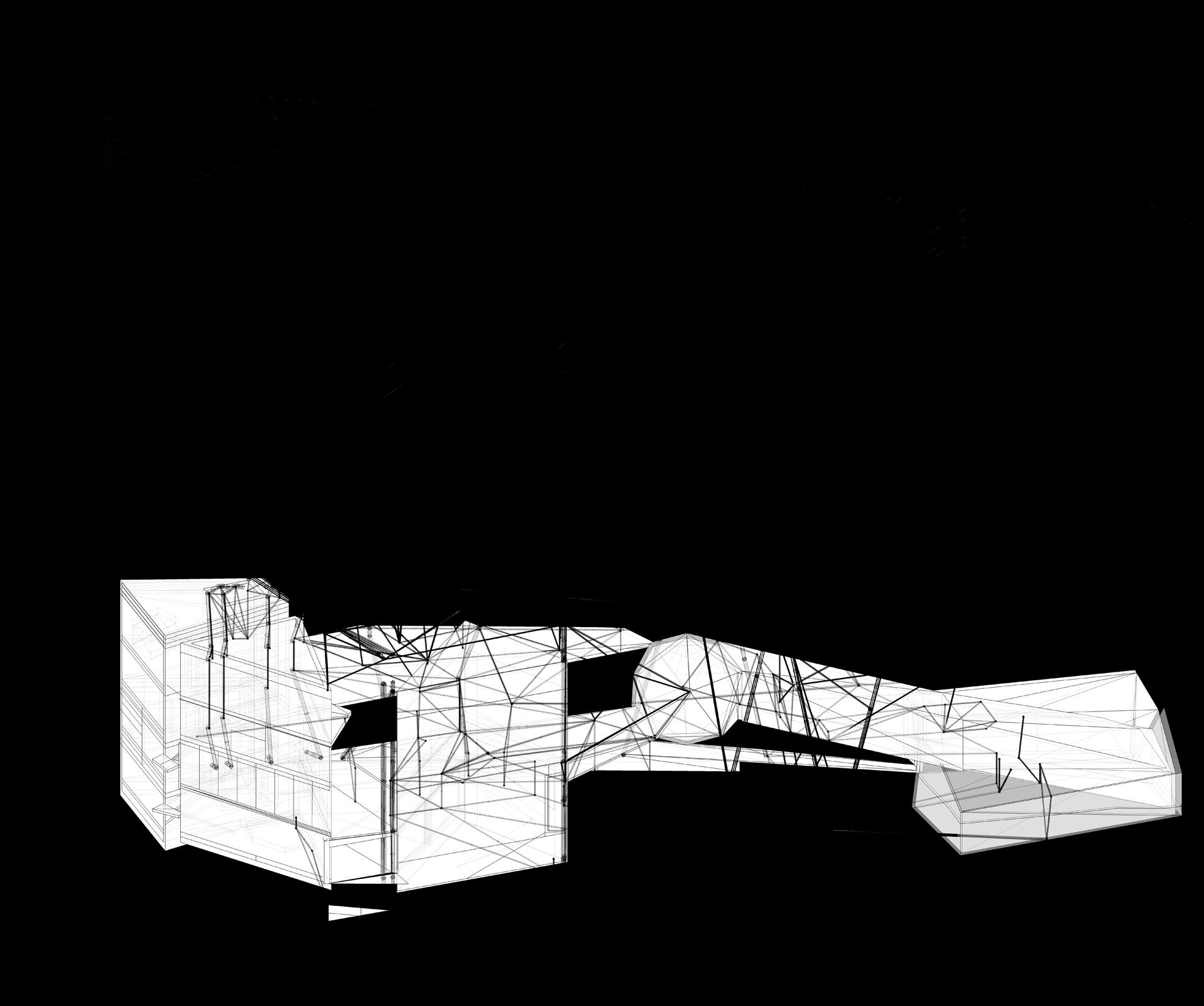
his project began in my second studio course, where I designed a workspace for a video game production company with in-house marketing, engineering, and design teams. Three distinct building modules—one per team— were linked by platforms, stairways, and ramps, connecting the in-house teams (left end of the site) to the public program (middle and right). initially developed the design in SketchUp, later refining it in my Sustainable Systems class. I revisited

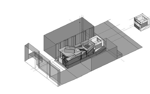
Above: left - Digital model of the re-engineered envelope; right - a hand drawn section cut through the dodedecahedral volume in the center where visitors can be scanned to create virtual avatars.
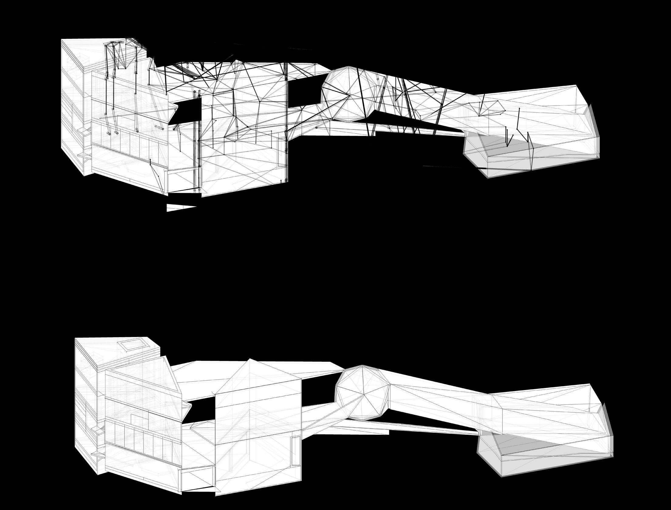
The work on this page began in my second studio course where I designed a workspace for a company that required in-house marketing, engineering, and design teams. Three building modules, one for each team, were then connected with platforms, stairways, and ramps that connected the in-house team seen on the left side in the diagrams here to the public program on the other side (right in diagram). I iterated in Sketchup but reworked the design in my Sustainable Systems class. The diagram here was drawn in Rhinocerous 3D and composed as an exploded axon in Adobe Indesign.
using plan and isometric views of the model to show (in red) the creation of a compound section drawing (bottom)
Left Diagrams
One Building: Two Courses
Structural
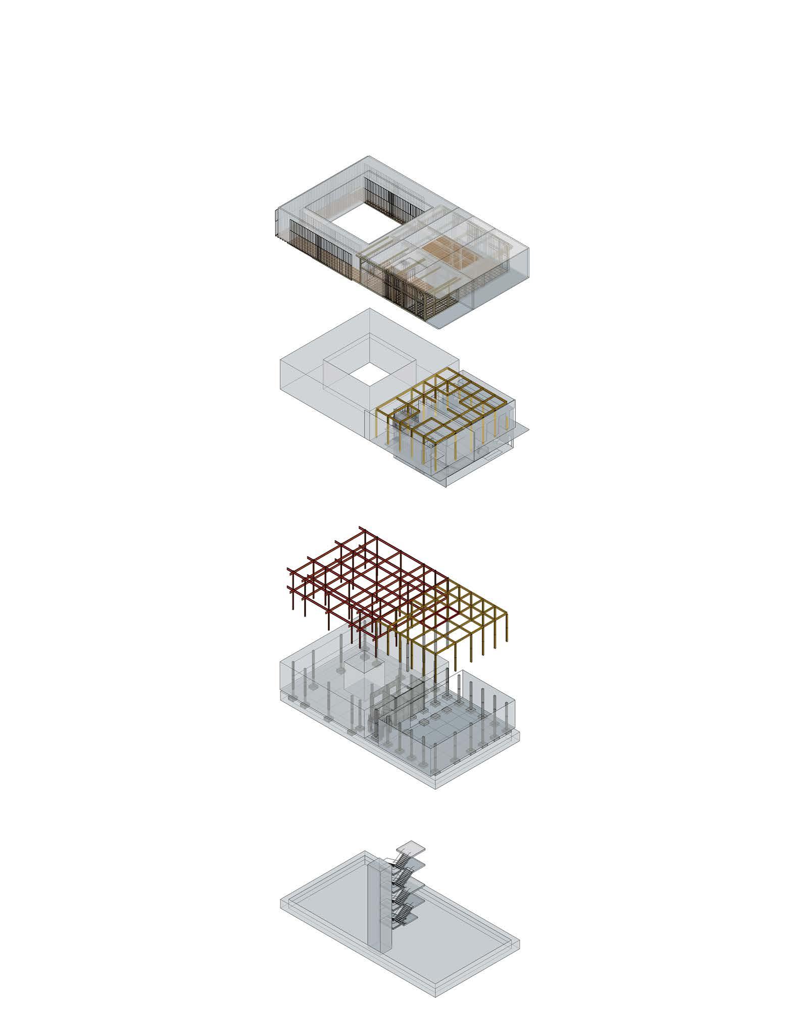
Structural Systems 2
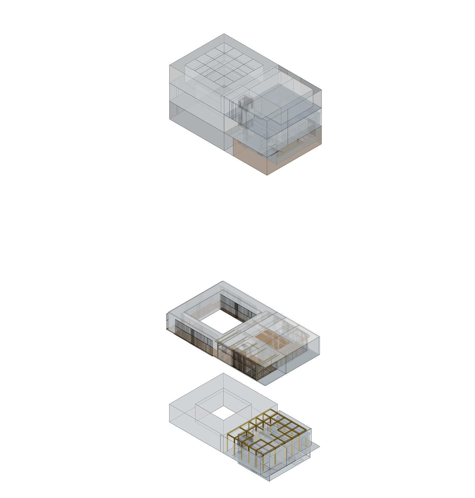

Adams Museum
ground level, steel on the second, and timber on the third. The façade required
BELOW:
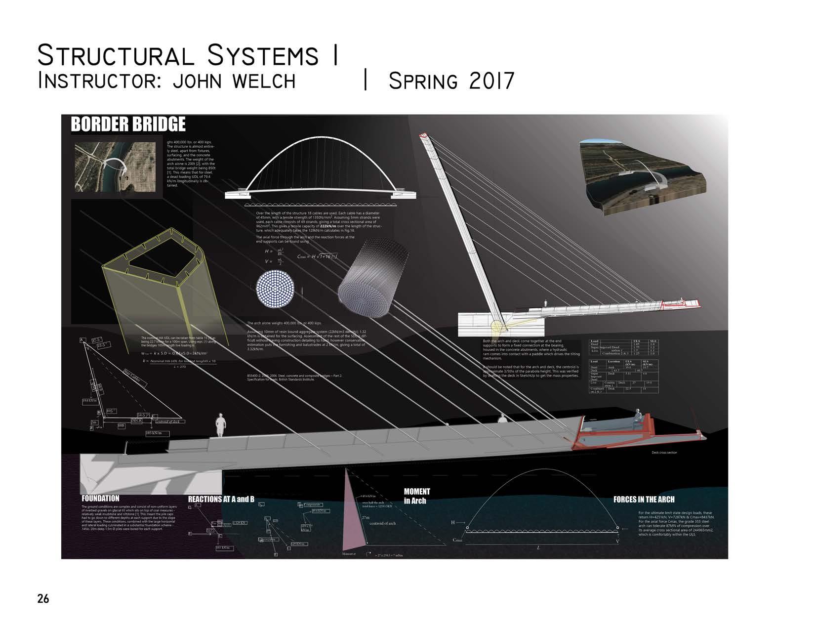
Final project calculating moments and reactions for a Parabolic suspension bridge that tilts.
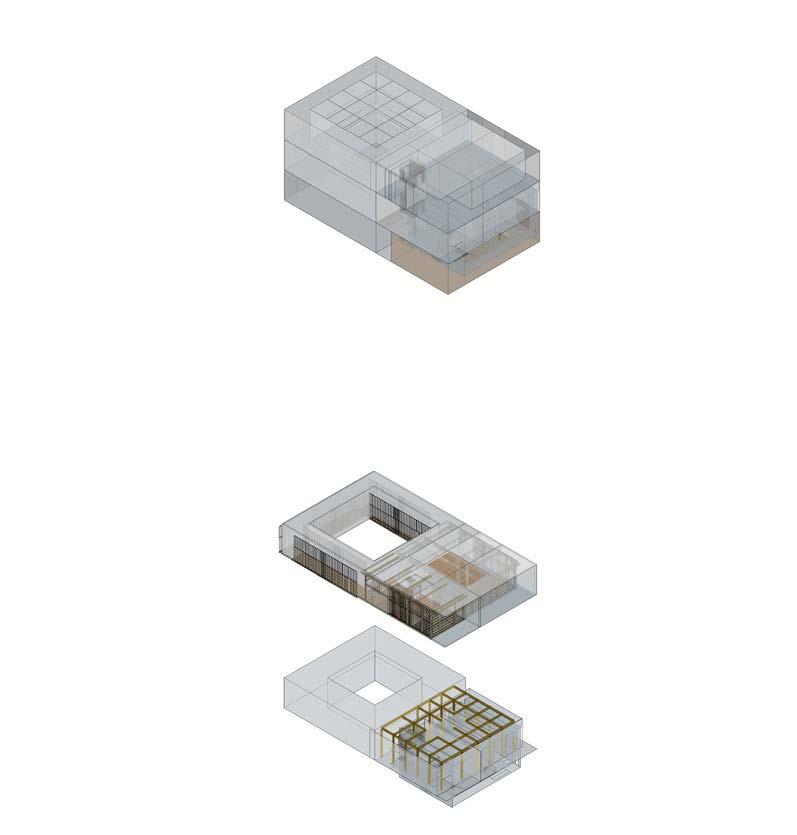
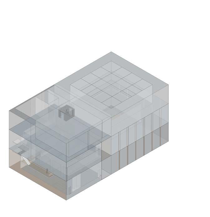
BELOW: My design subdivided the structure: one half (outlined in magenta) housed offices with 15’ ceilings, while the other featured an atrium with mezzanine floors connected to the offices

Sustainable Building Strategies Material Assemblies
The diagrams on this page originate from a course where I designed affordable housing. My solution featured six prefabricated dwelling units with shared walls and ground floor circulation space. I revisited the project with a focus on sustainability, designing to Passivehaus standards for energy efficiency. To reduce cost and construction time, I adapted the WikiHouse model, using CNC-cut 18mm structural hardwood plywood for framing. The wall system integrates 16 inches of sustainable
insulation (dense-pack cellulose or wood fiber), achieving an estimated R-value of 60-70. A hybrid solar chimney system is embedded in the exterior wall, thermally separated using wood fiber insulation and vacuum-insulated panels (VIPs). This design enhances passive ventilation while maintaining high thermal performance. WUFI software was used to model the assembly, confirming its effectiveness in meeting highperformance insulation standards.

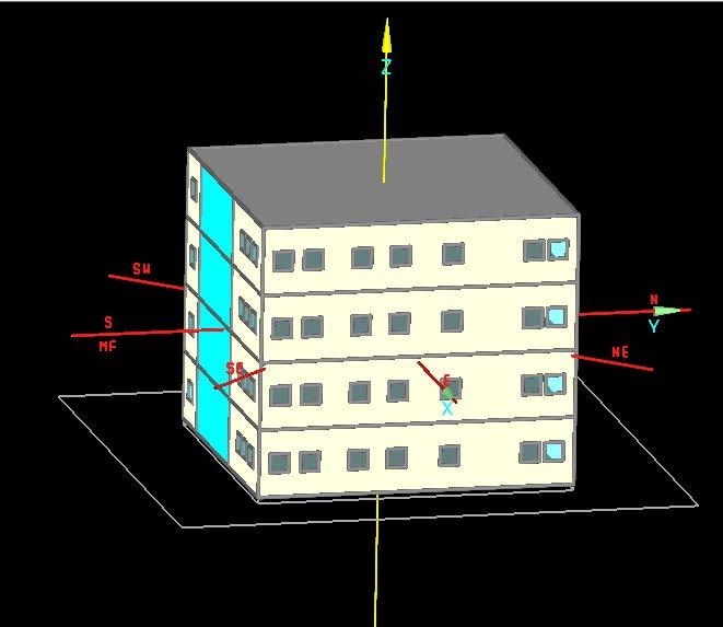
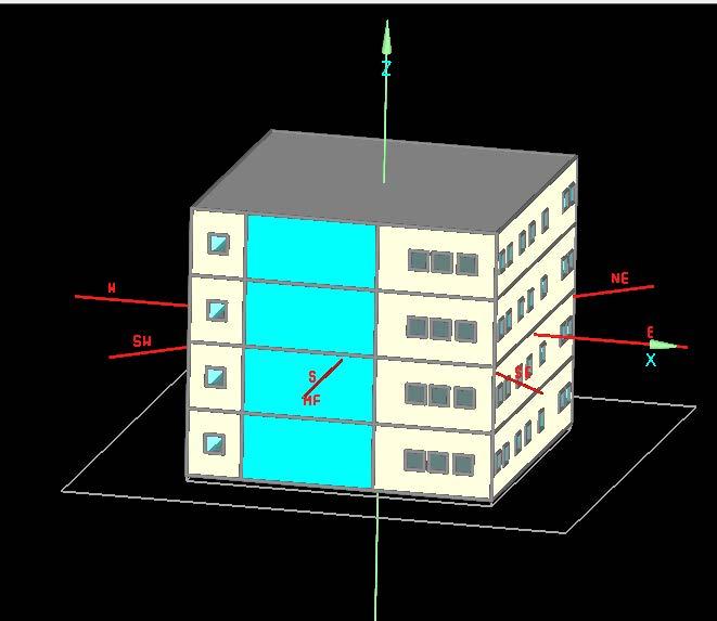
Left: Systems diagram showing a solar chimney built into prefabricated wall modules, balancing energy efficiency and ventilation. A thermally isolated air channel, separated from insulation by wood fiberboard and VIPs, directs warm air upward, enhancing airflow while minimizing heat loss. This design optimizes prefabrication while maintaining airtightness and Passivehaus insulation. The system, combined with SIPs and a doublestud wall, achieves an estimated R-value of 60-70, suitable for Climate Zones 5-7.

Solar Chimney Cross Ventilation through
Designing these volumes taught me how spatial layout impacts thermal comfort. Each unit balances double- and single-height spaces to optimize airflow, daylighting, and passive strategies like solar gain, sunshading, and wind protection. The psychrometric chart (below) contextualizes these strategies within the human comfort zone.
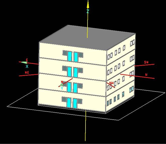
BOTTOM LEFT: WUFI Software Visualization showing an assignment where I learned how to calculate the energy efficiency of a four story building.
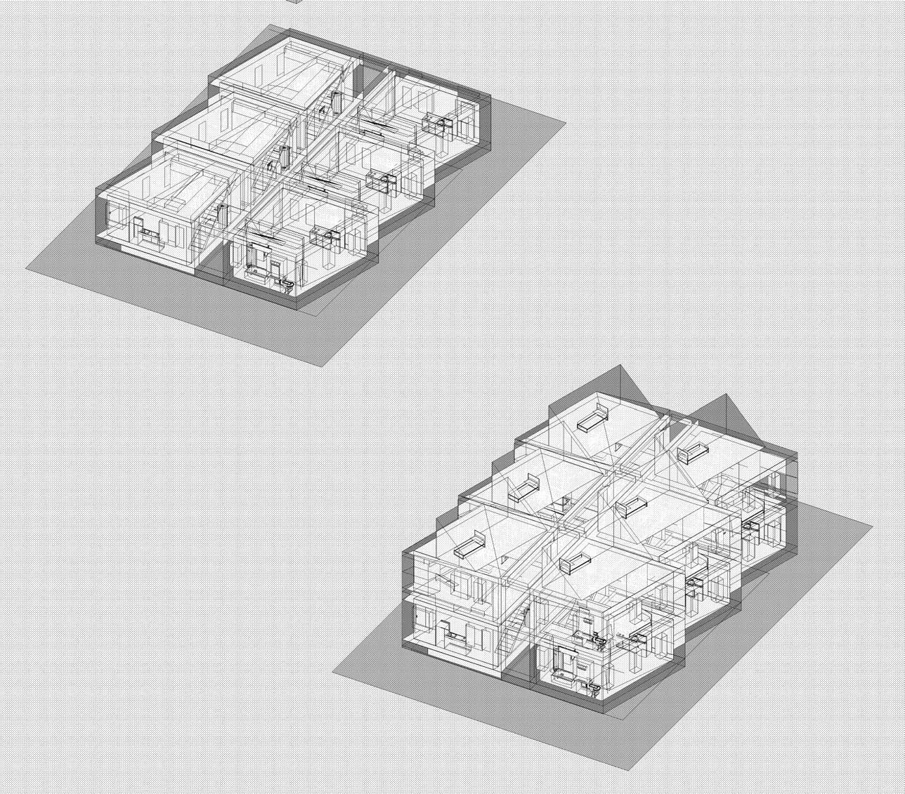
RIGHT: Isometric views of final 3d model with interior space highlighted and appliances drawn into the modules
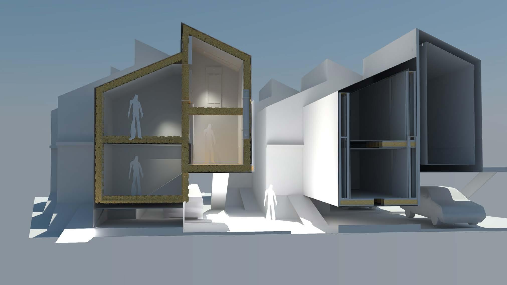
Right: Section diagram showing the Wikihouse framing members assembled.
Landscape Architecture Studio Comuna ∞ Medellín 2018
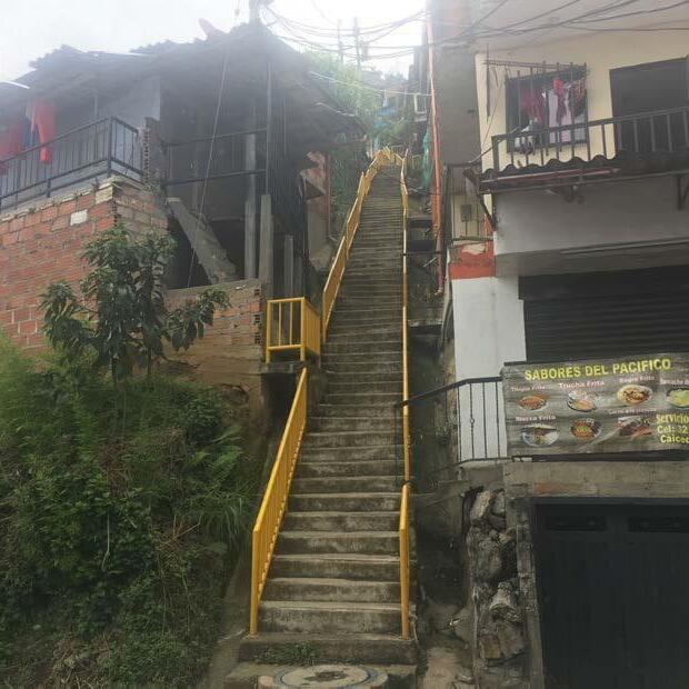
In 2018, I joined Boston landscape architecture students in a collaborative studio with UPB undergraduates in Colombia. My Spanish skills helped me engage with La Sierra’s community to understand their need for shared public spaces. Working with local leaders, we identified opportunities for parks and recreation areas. My design, Comuna Infinity, proposed a modular mega-structure integrating public and private spaces in phases. Using Rhino 3D and ArcGIS, I mapped buildable slopes for

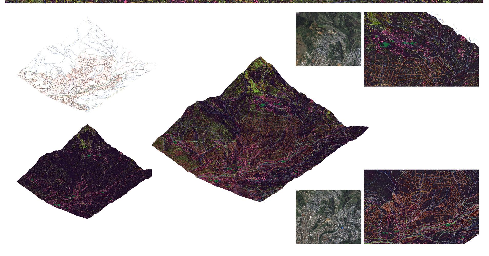
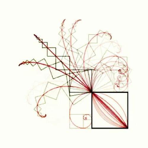
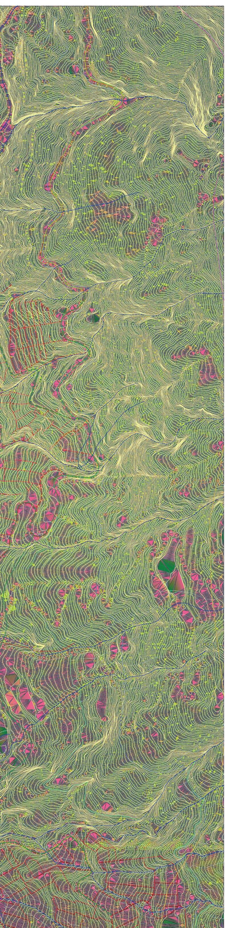
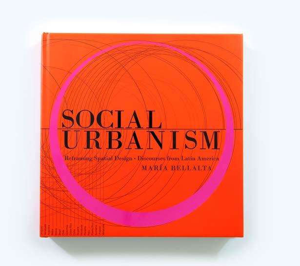
platforms and steep areas for erosion control. Inspired by the golden ratio, the design follows a fractal pattern where each phase builds upon the last, scaling down infinitely like a tightening spiral. This approach allows for sustainable growth—densifying without overwhelming the landscape, ensuring balance between urban expansion and ecological stability. My work and that of many other students was compiled by the BAC’s Maria Bellalta in the award-winning book Social Urbanism (2022).

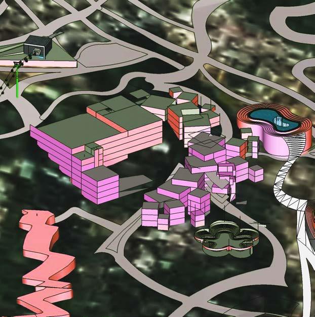


3D terrain model of La Sierra and surrounding neighborhoods
Concept diagram and renderings for platforms built off a structural “spine” built up over time.
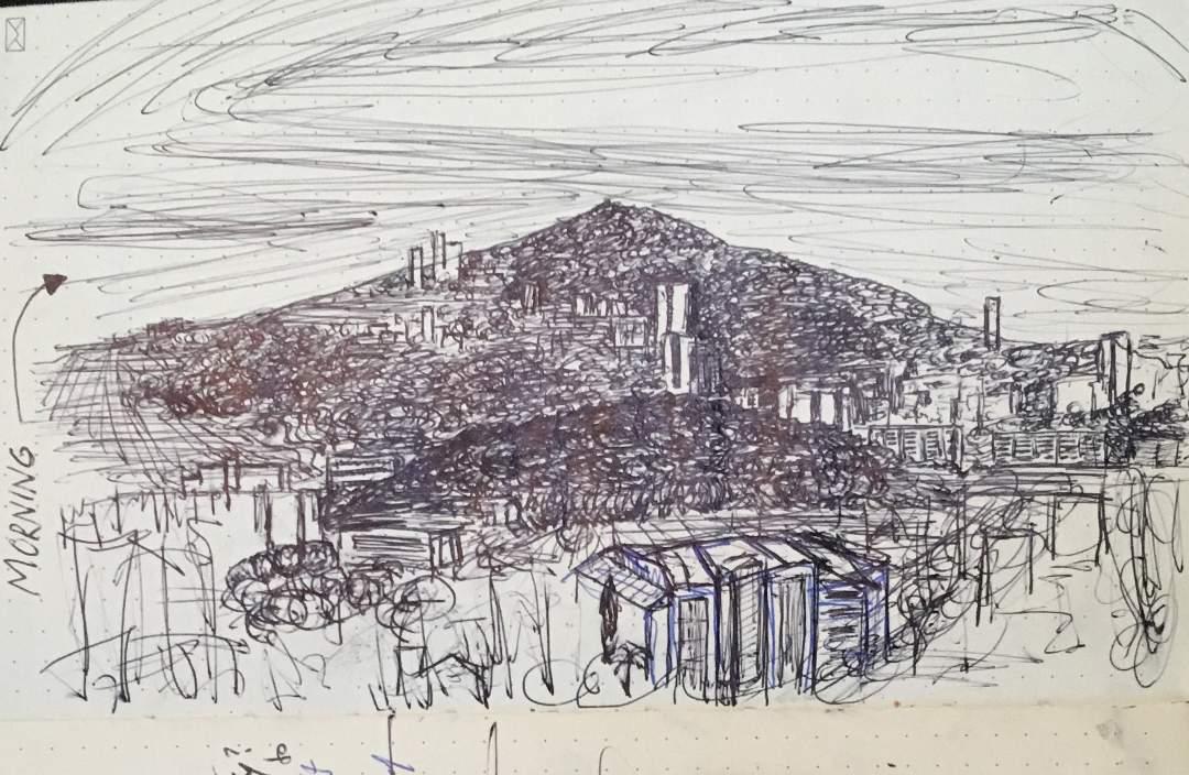
Above: sketch of Medellin Cityscape Below: Photographs of Medellin
Next Generation Indie Book AwardsWinner, 2022
Steep slope in 3D terrain model
Massing model in 3D terrain model
Buildable slope in 3D model
Fractal building complex in model sketch of same building complex
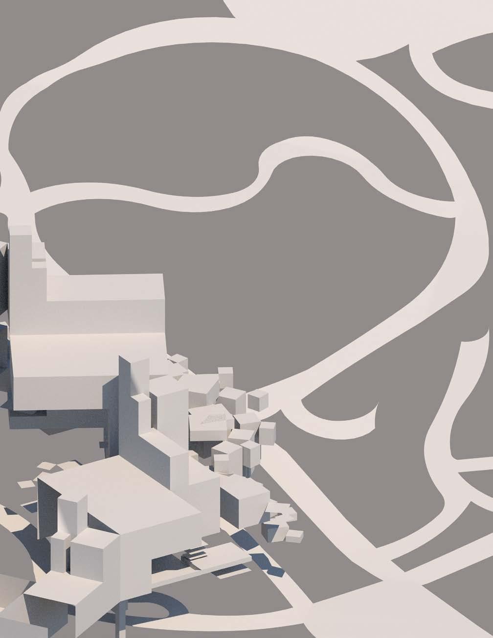
Architecture Studio 3
Site Work
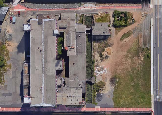
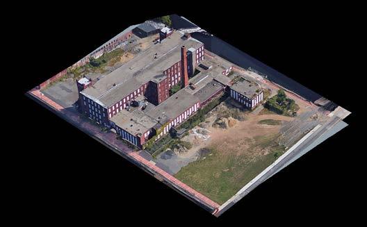
For my third studio course, the site was zoned as industrial maritime, but our designs focused on housing while addressing projected sea level rise (SLR). To meet the required floor area ratio (F.A.R.) of 3.0, I elevated the housing complex above 2070 high tide predictions, minimizing site impact while preserving public access to the landscape before it is reclaimed by the sea. I incorporated historic fire insurance maps to inform responses to this emerging threat and reintroduced

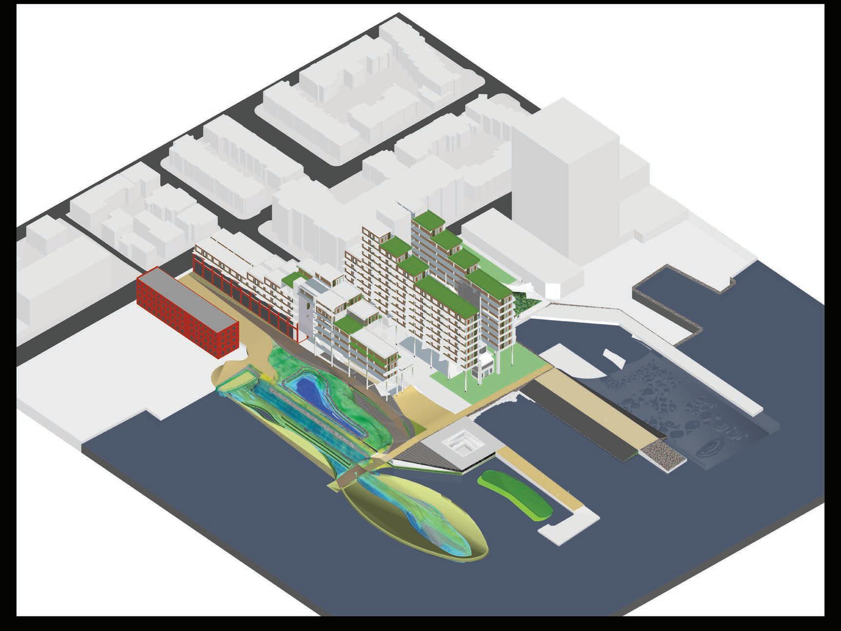
past wharf footprints as natural barriers and public amenities, shaping a sequence of elevated buildings, raised plinths, walking paths built over retaining walls and landscape design that brings back native species to regenerate the saltwater marshes and decidious coastal forests that once occupied the transition zone between ocean and dryland known as the ecotone. This was designed as part of the Climate Ready Boston initiative.


Below: The effect of Sea Level Rise on the site is not nullified but safetly mitigated by design interventions on the ground and the raising of all new construction well above projected water levels in 2070.
Right: Collaged Rendering that features the public parkspace designed to be inundated one day but in the present as a beautiful restorative landscape with natural water features like tidepools and marsh grasses as well as a watefall built into the seawall
Left: Site diagram shows average Sea Level on site in 2020 and 2070
Right: Section diagram shows one building complex and storm surge sea levels
Architecture Studio 4
Schematic Design
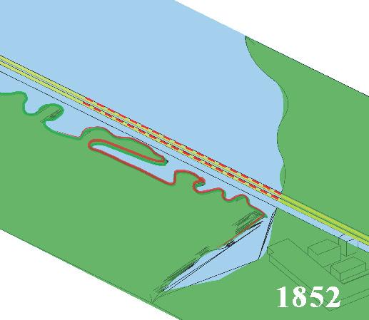
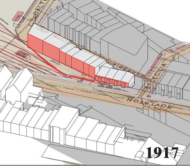


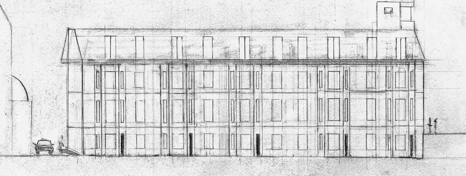
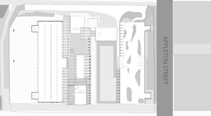
My final Advanced Architecture Studio at the Boston Architectural College focused on sustaining design momentum from concept to technical details. Initially in person, the course shifted to remote learning due to the Covid-19 pandemic. The project proposed an extension of the BAC over the Commuter Rail line along the Massachusetts Turnpike. Research revealed that this transit corridor was the first major cut into the estuary landscape, later occupied by stables repurposed into
LEFT: Site research I used to generate the massing for my design shows how the built environment developed from train tracks in 1852 to the buildings in 1917 on to the site today.
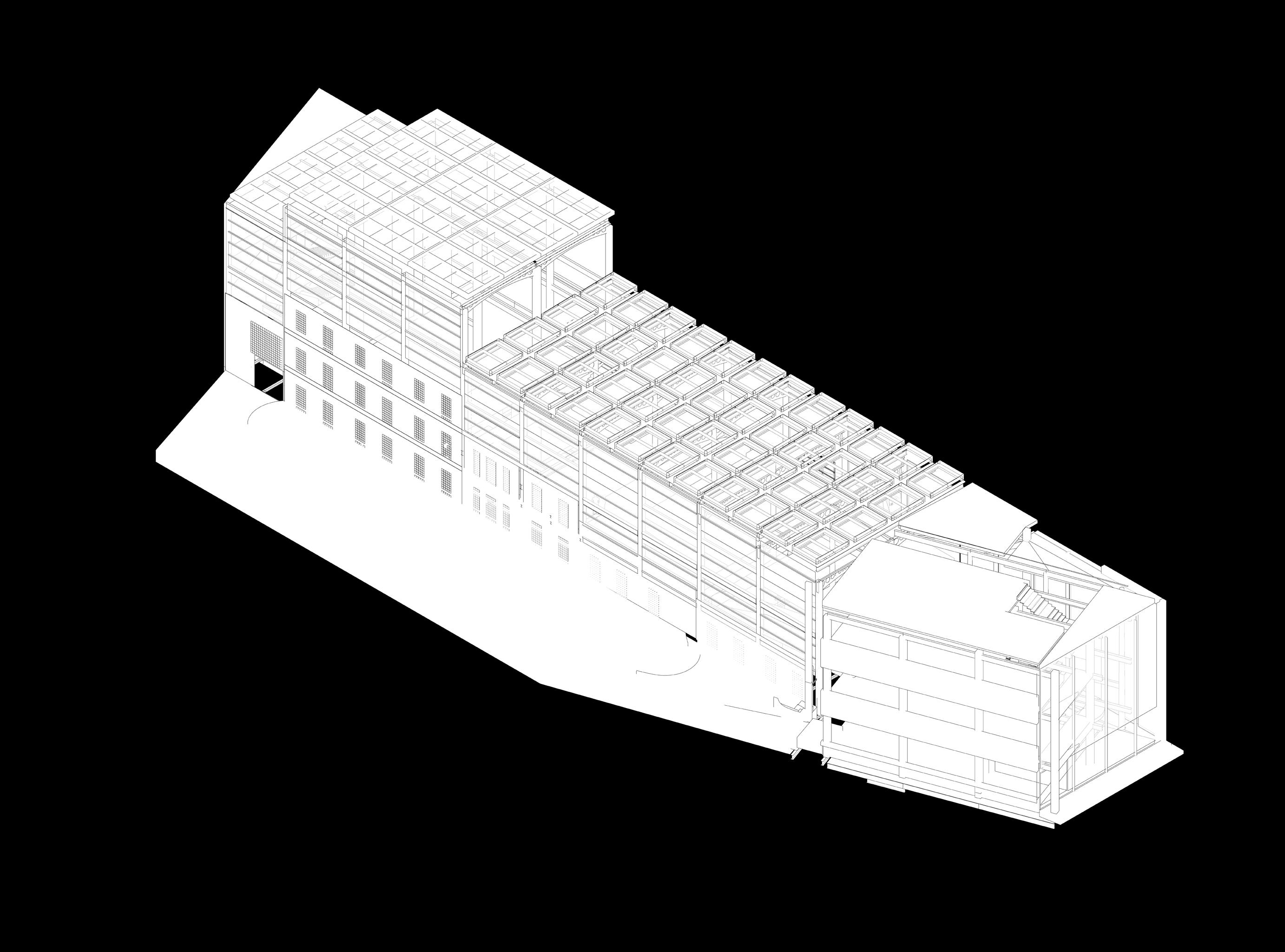
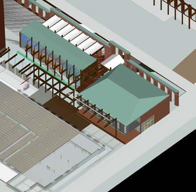
row houses before being razed in the 1960s to make way for the out-of-scale Hynes Convention Center and Parking Garage. My design sought to reclaim the site with a footprint that combined elements of the stables, rowhouses, and modernist forms, incorporating a structure where students could construct large-scale models—designed to be placed on a mezzanine floor or suspended from a glass ceiling.
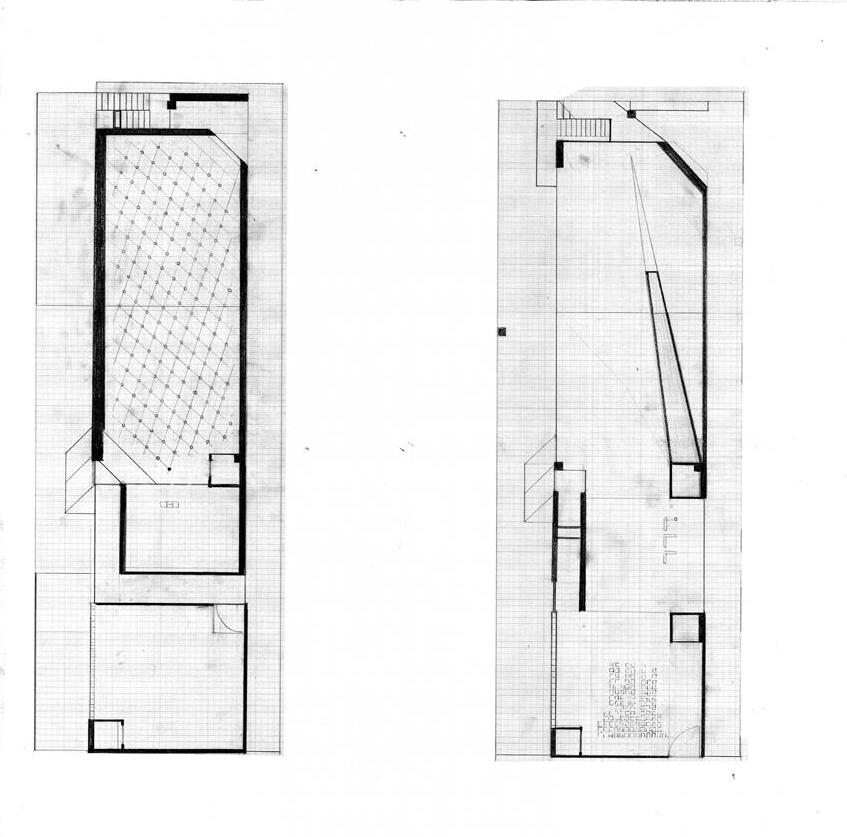
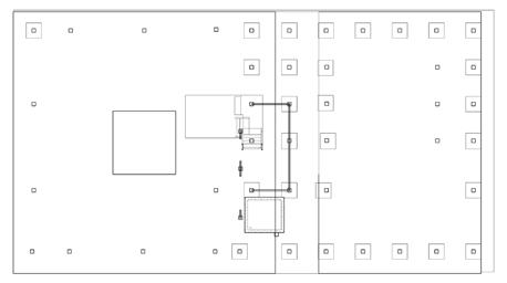
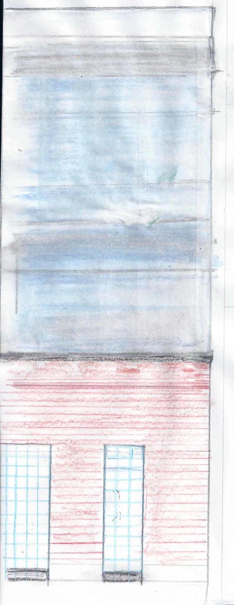
BELOW: Final Design: floorplan with column grid
BELOW: Detailed Section Drawing showing, brick, glass block, and curtain wall elements

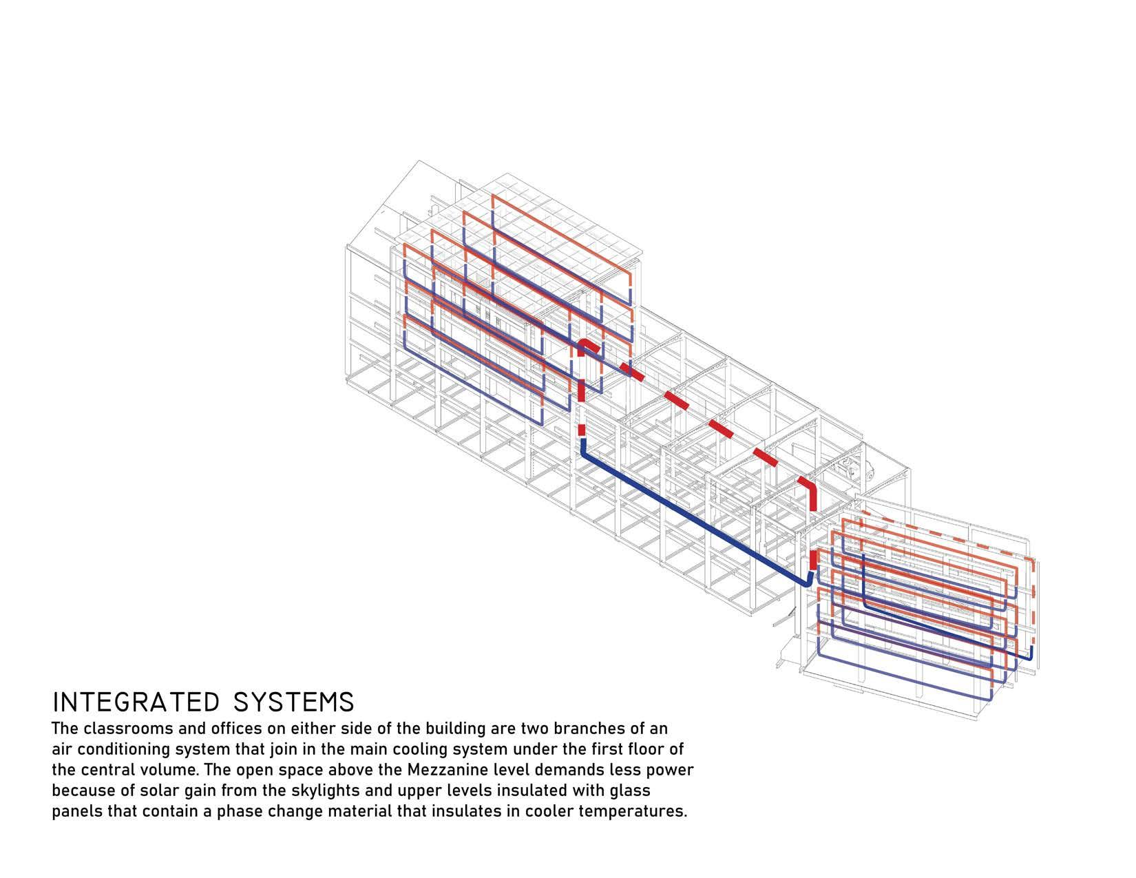
Systems: Coordination of HVAC System with
floor
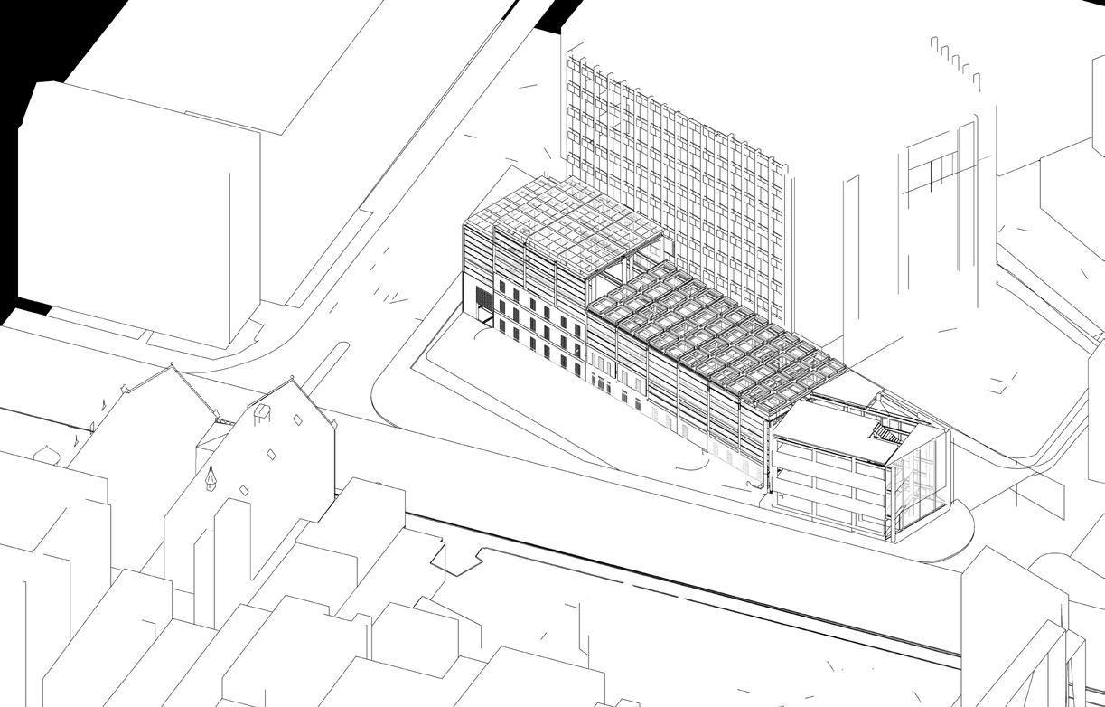
SE ISOMETRIC
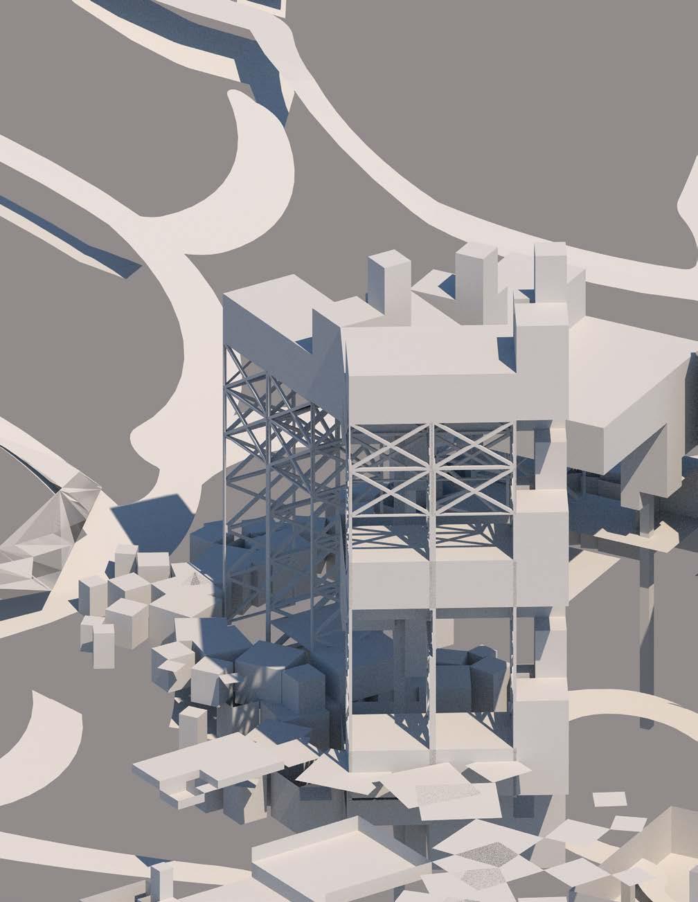
Architecture Masters Thesis
Making Ways
Reframing An Old Mill Complex As A Multi-Purpose Destination, Emphasizing Circulation And Informal Gathering Spaces Through Master Planning.
INTERWEAVING CIRCULATION AND PROGRAM
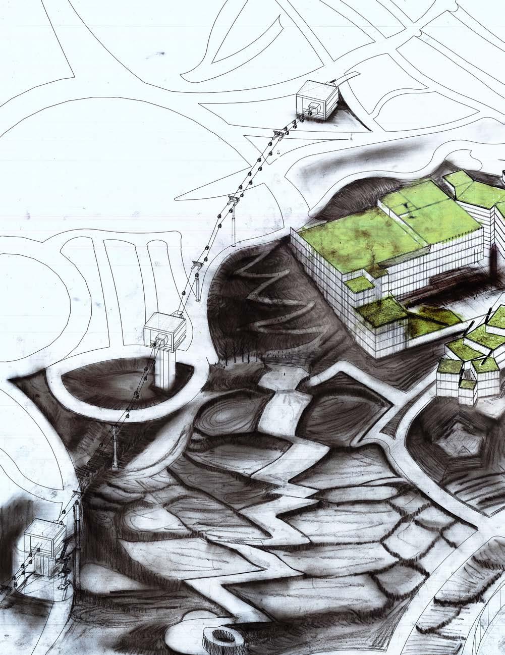
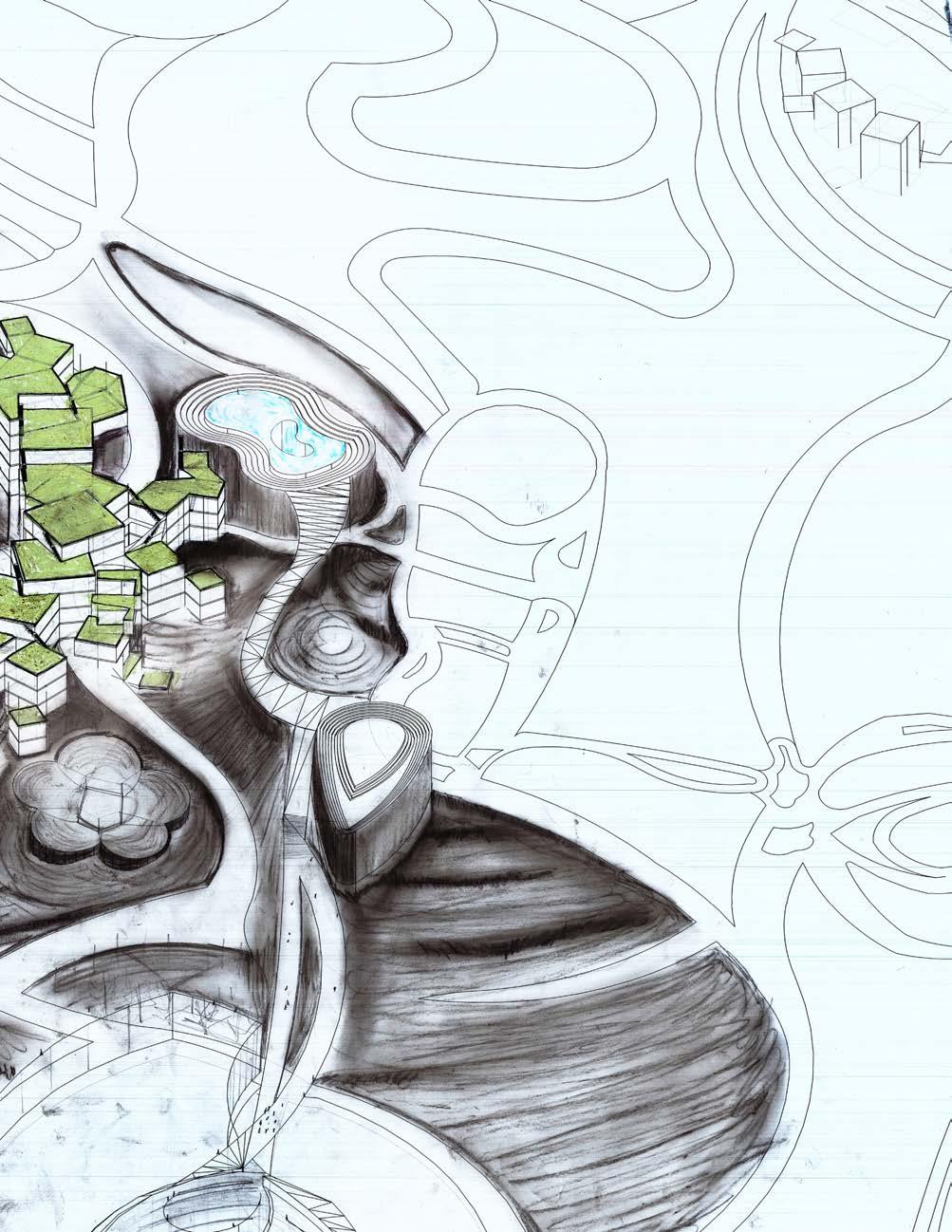
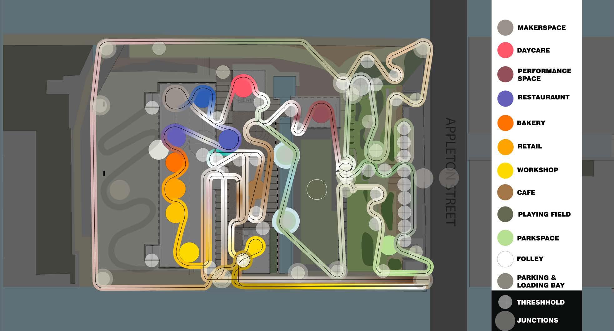
Making Ways explores adaptive reuse and master planning to transform a former thread factory in Holyoke, MA, into a dynamic mixed-use destination. The design prioritizes circulation, interweaving paths of different users to create moments for gathering inside and outside. A network of pathways and program` nodes— including workspaces, retail, dining, and community spaces—activates the site, while the mixed-use design balances public and private spaces. A park and flexible
gathering areas encourage activity at the edges, while housing is planned for the upper floors of the existing mill, with shared workspaces and gyms for residents and neighbors. Pathways guide movement between spaces, reinforcing connection and discovery. By integrating circulation, program layering, and adaptive reuse, the project reimagines a disused industrial site as a vibrant, interconnected place for work, living, and community.


PATH


THREE CORE PROGRAMS TIED TOGETHER

ABOVE: Each distinct program is designated a node with distinct color. The opaque markers indicate thresholds where I envisioned paths crossing. The circulation paths connects the nodes and passes through the thresholds. The colors of the path change as they pass through program and become white in the gathering spaces.
/reacting to the present PREPARING A MASTERPLAN


RIGHT: The tonal scale is used to indicate a spectrum of
Architecture Masters Thesis
Making Ways
Reframing an old mill complex as a multi-purpose destination, emphasizing circulation and informal gathering spaces through master planning.
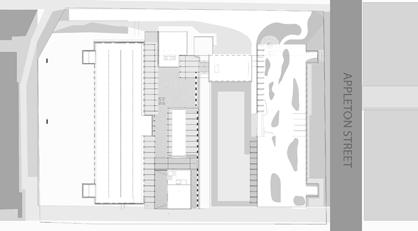
I focused my design concept on circulation, weaving together the paths of different users to create dynamic moments for gathering. The diagram below shows how this network of interwoven pathways connects programmatic nodes marked by color-coded circles. These nodes—workshops, offices, retail, restauraunts, housing, daycare, and open spaces—activate the site throughout the day and into the evening. In addition to the existing factory building I started with the footprints of
past buildings to design new buildings to accommodate workshops, café, and daycare facility, reinforcing shared daily rhythms, while upper floors of the factory building contain private residences with shared amenities. Outdoor circulation links gathering spaces, from flexible plazas to a water garden and performance areas. By shaping movement and encounters, the project fosters layered interactions, ensuring the site remains vibrant across work, recreation, and community life.

Architecture Masters Thesis Making Ways
Processional Thresholds & Spatial Transitions
The design of Making Ways is structured around key thresholds that define movement and spatial experience, reinforcing the adaptive reuse strategy through layered transitions between public, semi-public, and private spaces. Circulation pathways bring people together— residents, workers, and visitors—guiding them through a series of gathering spaces framed by the site’s historic and new interventions. Thresholds such as the Canal
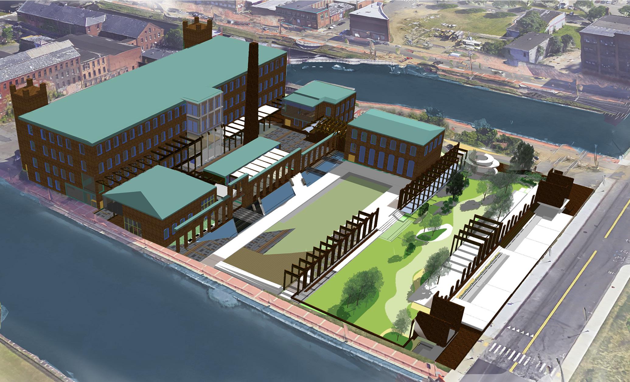
Walk Between Mill and Workshop, the Plaza Between Café and Mill Building, and the Park Space and Folly serve as pivotal moments where circulation converges, programmatic elements overlap, and the experience of space is heightened. These transitions frame connections between work, social, and leisure spaces, ensuring a dynamic flow throughout the reactivated site while preserving and reinterpreting its industrial past.
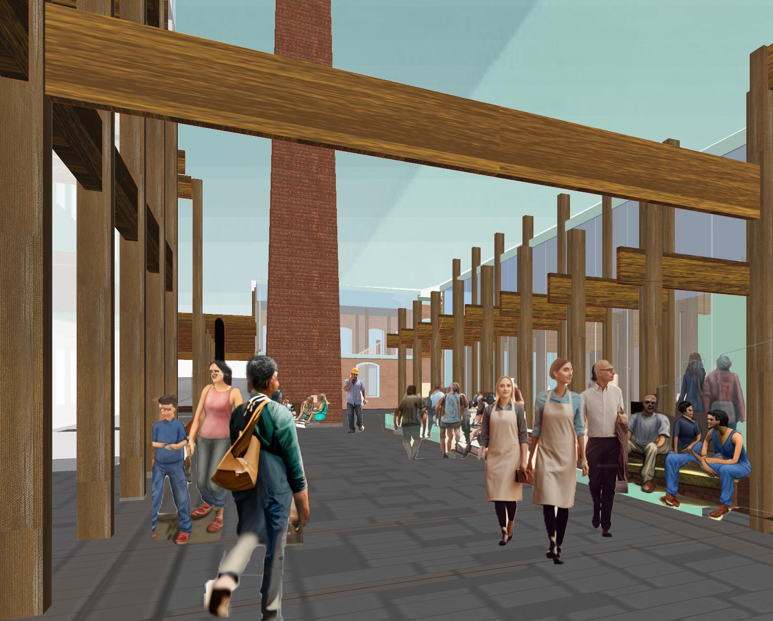
THRESHOLD FIVE PLAZA
BETWEEN CAFE AND MILL BUILDING


THRESHOLD FOUR CANALWALK BETWEEN MILL AND WORKSHOP
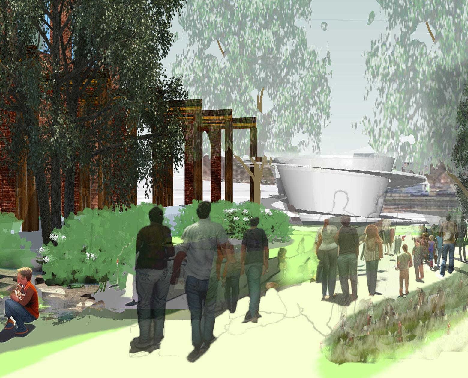
THRESHOLD EIGHT PARK SPACE AND FOLLEY
Above: Birdseye view of the final site model show the existing building with its steeple-like chimney connected to two and one-story new buildings. The timber threshold stuctures that appear throughout the site are the one constant feature across several distinct zones. Also of note, the small canal between open green space and new buildings.
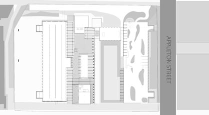
Above: Perspective view paired with a plan (top right) and isometric call-out to orient the reader, looking at a shared open space, cafe to the right, and the existing chimney
BELOW: A perspective view of the park space. I proposed building false ‘ruins’ of the large factory building that had one been there (see isometric call-out) but also a folley with a ramping circular form.
Below: Perspective view paired with a plan (top right) and isometric call-out to orient the reader
Professional Work Design Build
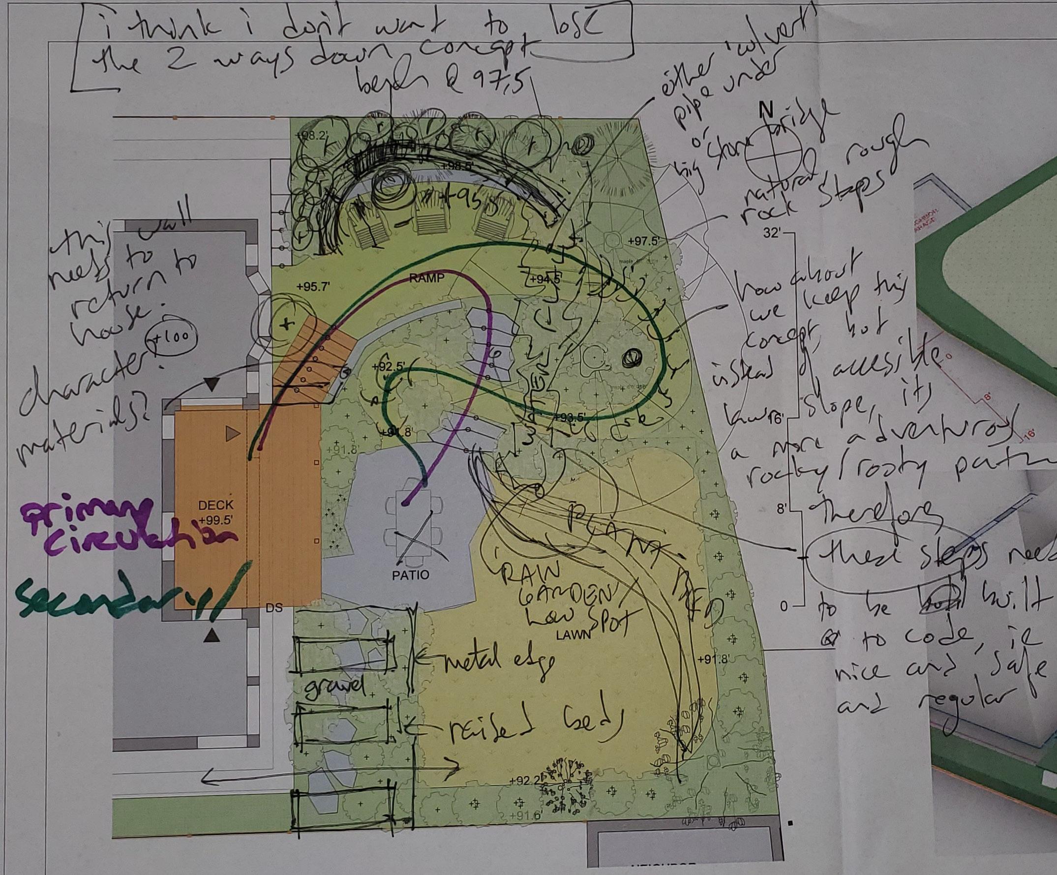
Above: Redline drawings with comments from Rob Gilmore during Design Development


Since 2019 I have worked at Gilmore Landscape Architecture directed by principal Rob Gilmore, PLA. I was one of a four person design team. This was also a time of year when I would meet with clients for preliminary design meetings. In the spring, Gilmore and the design team joined up with an additonal build crew. We spent 6-8 months working in the field planting and building with an additional wave of design work and correspondence with fabricators, carpenters,
masons, and of course clients. I personally built fences, walls, decks and patios but if the project called for more extensive work we engaged with contractors. At GLA I not only learned the fundamentals of landscape architecture but also how small scale projects are designed, negotiated, and then built from the ground up. This section focused on my professional work begins with the first project I helped to manage, on a hillside in Newton MA.
Technical Skills


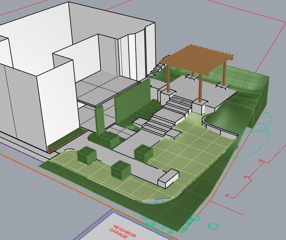
Right: My team delivered a set of four concept plans to the clients which not only showcased the range of our building abilities but also offered a contrasting set of ideas to help the clients to consider what aspects of the design was most important to them.


Right: A section drawing used for internal use only during design development to determine the length of the stairway and determine the amount of stone for a Cost Estimate.


North-South Section - Retaining Wall, Patio and Stairway
North-South Section Drawing of Waterfall


Backyard Escape
From Conceptualization to Design Implementation
Gilmore Landscape Architecture
Lisa and David Swartz
Outdoor Porch, Patio, Planting, Water feature
Schematic Drawings
Location: Newton Massachusetts
Project Designer, Building Phase
My idea to design the stairs at angle was a response to the bay window, an addition from a decade before that now presented an obstacle to the new, wider steps that I had recommended. I was tasked with drawing this framing plan to communicate my idea to the carpenters who worked with us to build the deck and steps.
Add more to this later. In Newton Corner, nestled up close to Boston with a view to the Pru and a public golf course in between. Up to this point I had not wokred on a project with a client from the beginning. Instead, I had entered into the process after the client had signed a contract for designservices or building services. In this case I helped to bring this project to our firm (Bidding & Contract Negotiation)and was involved from initial site survey to contract writing and negotiation. Our team moved forward with a set of design concepts that gave the clients a brand new feeling to their outdoor space. I developed the technical dawing for a portch with timber and composite construction and suggested a special design for the stairway down to the patio . Through many iterations that developed from sketches to CAD plans to SketchUp models we worked together to reach the final design which combined aspects of each designers’ ideas. Our mason suggested we use a locally-quarried stone which the clients loved. We built a waterfall for the first
From Design to Build
From Design to Build
From Design to Build
Design Skills
From Design to Build
From Design to Build
From Design to Build

Design
a recent addition to the design, my draw-

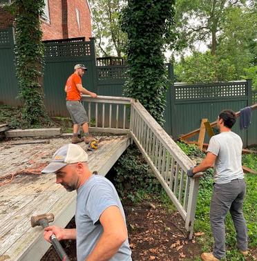
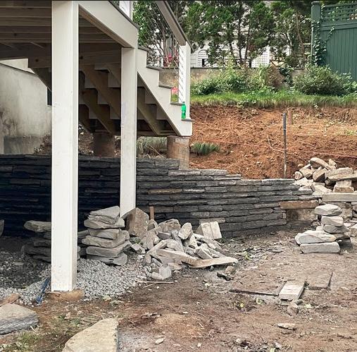

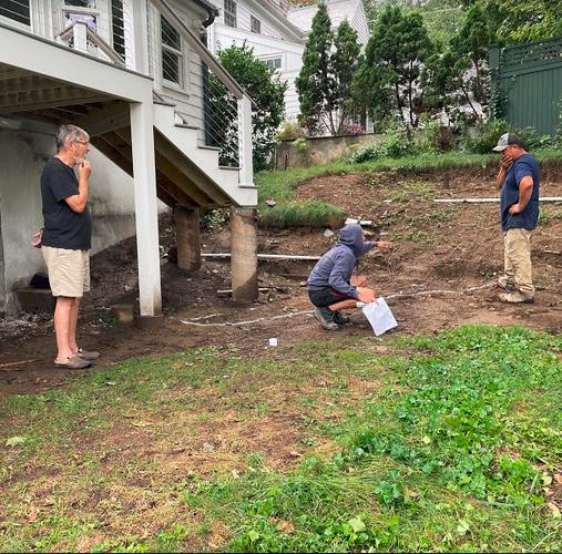
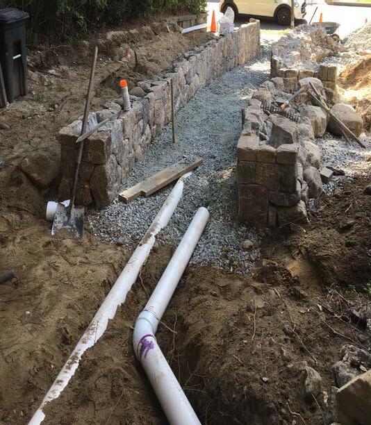
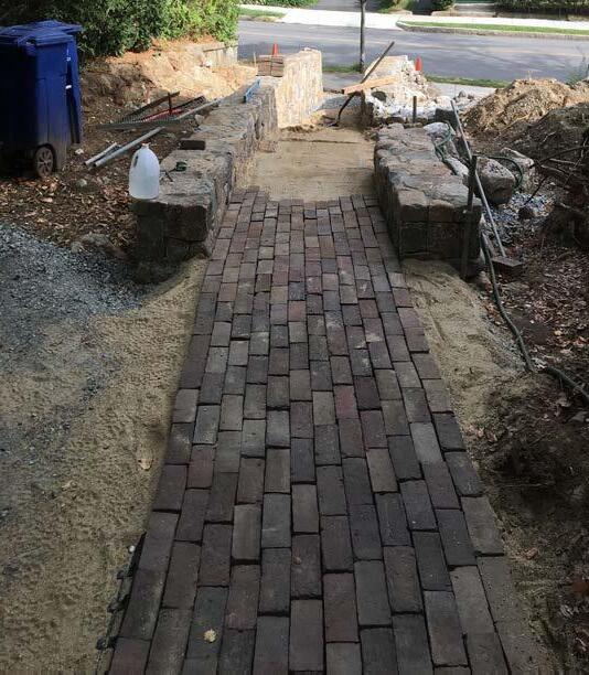
Design Build in progress! From top left: the yard before demolition, clients reviewing a set of ve concept plans with 3D models, Demolition of the lower deck, Meeting of minds between Rob Gilmore, and the Mason with client to the left, the retaining walls being dry laid, the steps almost nished, the nal planting of the upper patio
in progress! From top left: the yard before demolition, clients reviewing a set of ve concept plans with 3D models, Demolition of the lower deck, Meeting of minds between Rob Gilmore, and the Mason with client to the left, the retaining walls being dry laid, the steps almost nished, the nal planting of the upper patio
Design Build in progress! From top left: the yard before demolition, clients reviewing a set of ve concept plans with 3D models, Demolition of the lower deck, Meeting of minds between Rob Gilmore, and the Mason with client to the left, the retaining walls being dry laid, the steps almost nished, the nal planting of the upper patio
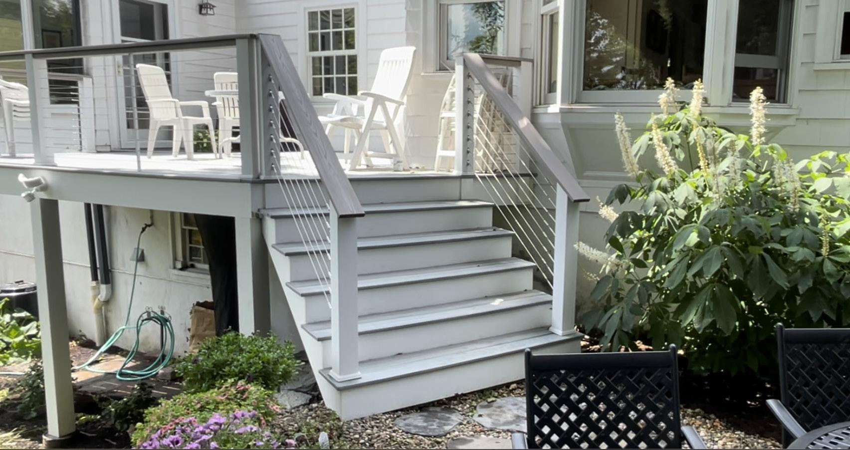
I hadn’t had an opportunity to design a building detail until this Conceptualization stage I developed the ideas for a nonorthogonal joint between a new porch and new stone patio as well as a round seating wall. I was excited that my ideas made it into the final design and looked forward to building them too. A lesson in & Workplan Development was the contractors: the existing porch would be removed and new porch built by one set of carpenters and the stone retaining walls and seating walls by another. I was asked to send the carpenters a framing plan of the porch along with an elevation. What was missing was a detail drawing of the railings. When it came time to build the railings the carpenters figured their own way out without w drawing. They were able to construct the “shifting stairway” but not without an unsightly junction between flat railing and stepped railing. While they had followed my drawings, they had built the railings with square posts and tension cables that did not line up. I learned from this experience that I had not fully understood that the cables could only be tensioned into posts at right angles. If I had understood this I would have reassessed my drawing. I also designed rounded walls thinking they would be mortared blocks but the masons recommended dry-laid walls made with stacked stones. In doing this, they made their job more difficult but I could not argue with the beautiful results and took pride in the final product.
Left: Once the stone steps had been built we could determine the precise design of the steel railing for metal workers. The crucial part was the angle at which the railing bent to follow the organic form of the steps.
Left: Details that I drew to specify to the carpenters how we planned the footings and joints between joists and posts to be built.
is a caption! Rum cone consed quiatetur magnis si dis dion cus aspicium facearc hitiam fugia si del int autem nimus niat aut ut repe sinisciet quis auta ius accabor eprepe volor aut aut laborro tem aditae quam lam rersperiati od
Daniel Swartz
Daniel Swartz
Daniel Swartz
RIGHT: A decking plan drew for the carpenters. The detail where the joists meet the posts was laer complicated by the tensioned cable railing
BELOW:
ing for steel workers to manufacture
Bay Window
Clockwise from top left: Photo from Existing Conditions, clients reviewing Design Concepts, Demolition, Rob Gilmore consulting with a Mason, retaining wall under construction and steps.
Professional Work
Before & After Construction
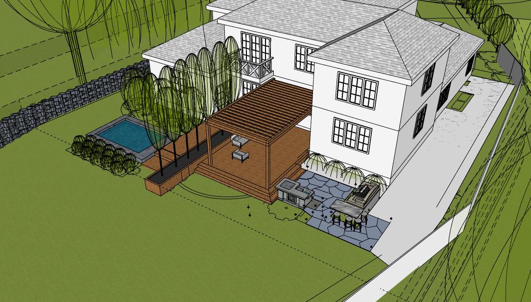
One concept model brought into a
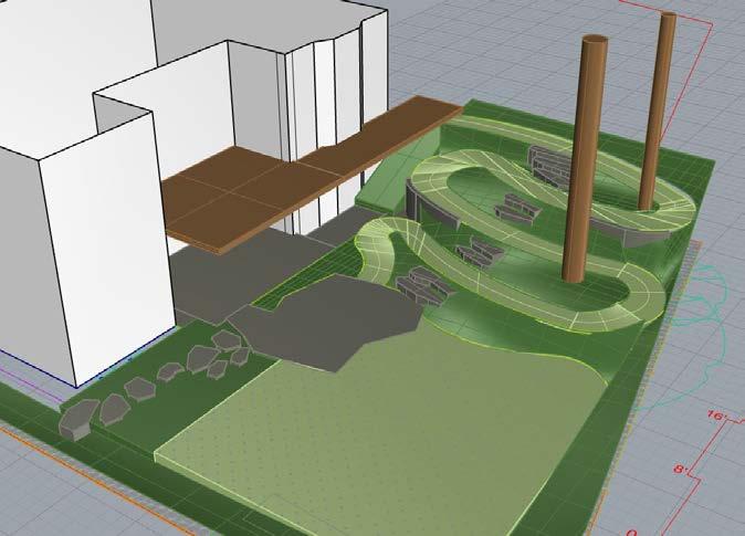
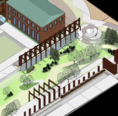
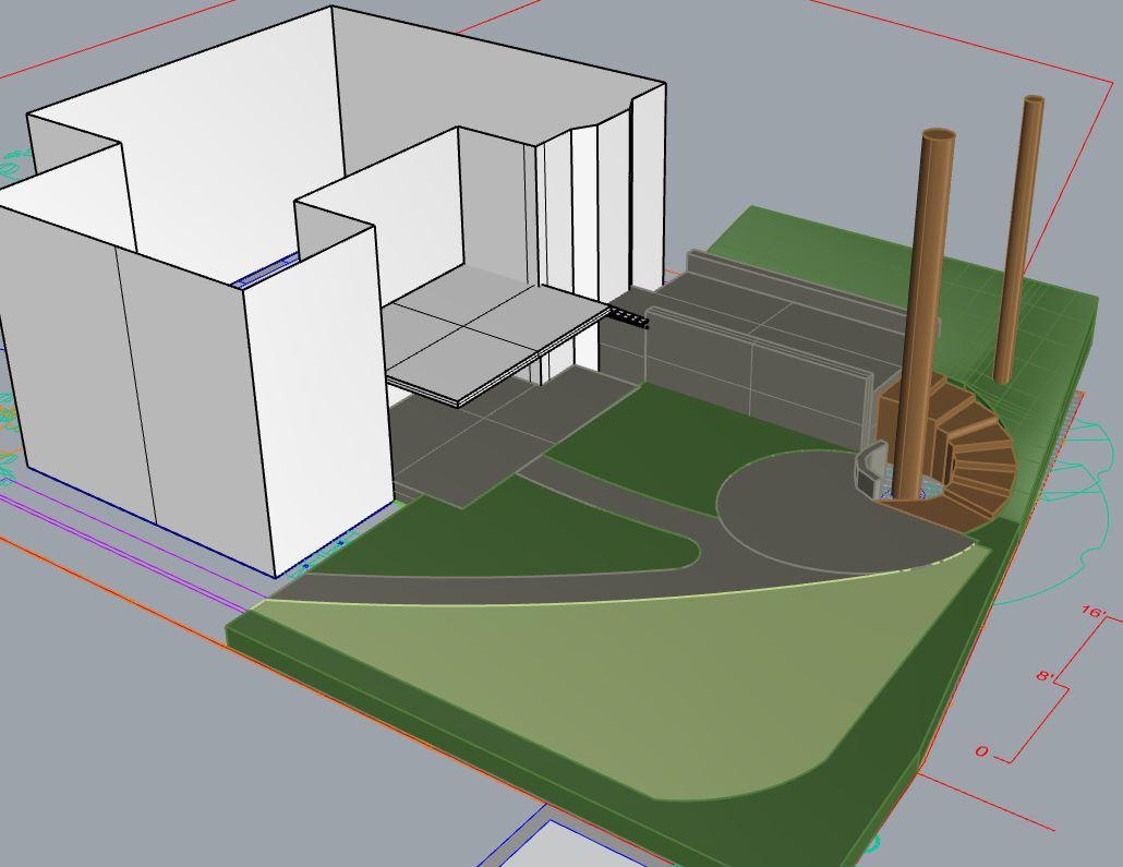
3D model extended the upper deck and contrasted the shear retaining wall with a winding planted hillscape
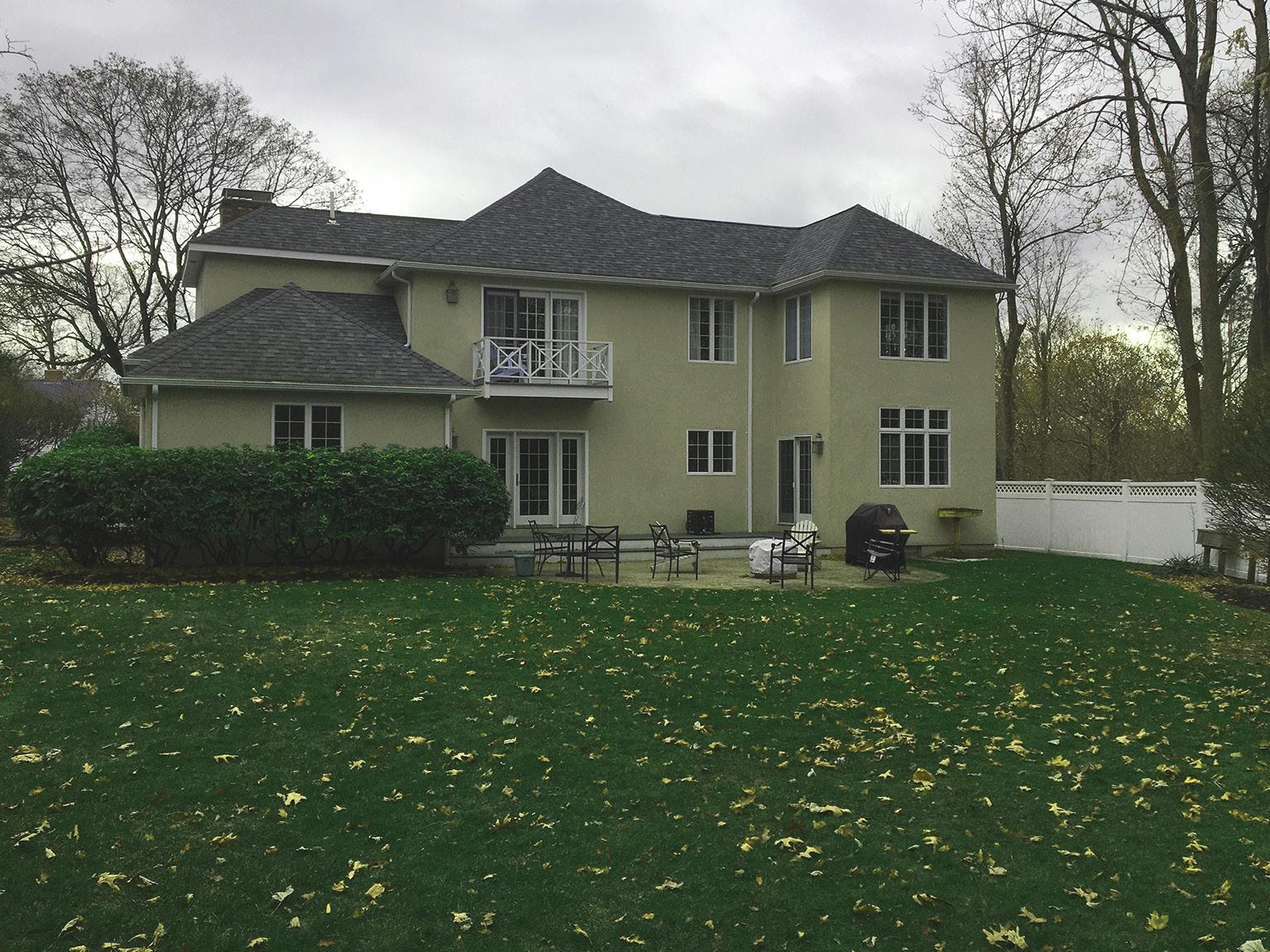
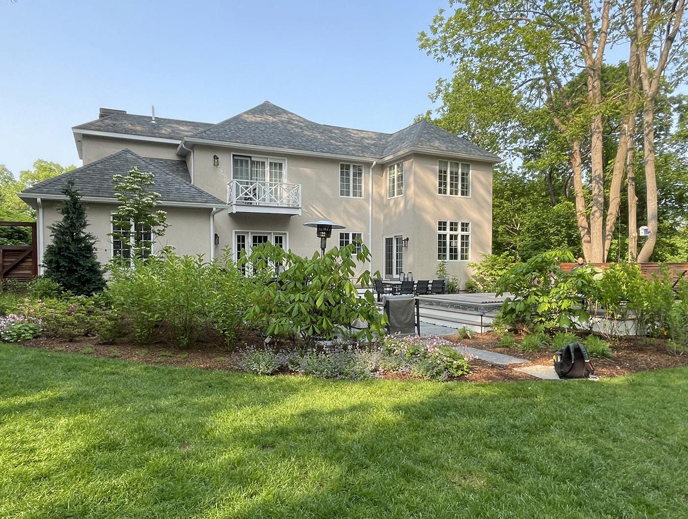
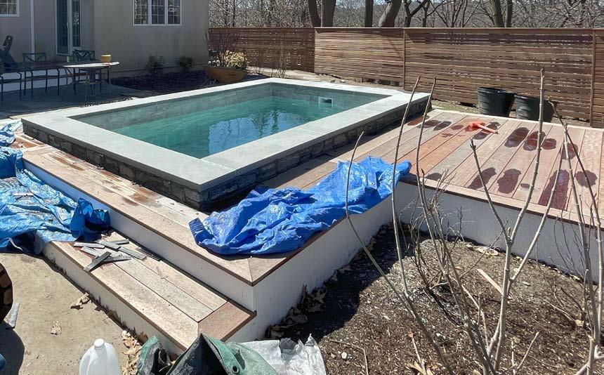
From 2019 to 2021 GLA worked with the clients to complete this project. I was responsible for managing the project and found the process challenging at times but very eduacational. The images on this page show a true transformation. Originally the back yard had been empty except for grass. The previous owners had built an above-ground pool connected to a shallow deck (left). Working with GLA, the clients finally got the dynamic backyard space they had always wanted. I was especially
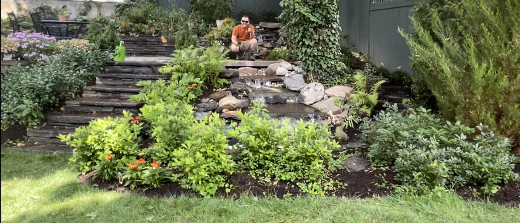
proud of the work our building team did to assemble the waterfall (below), the longest run that anyone at GLA had ever designed.
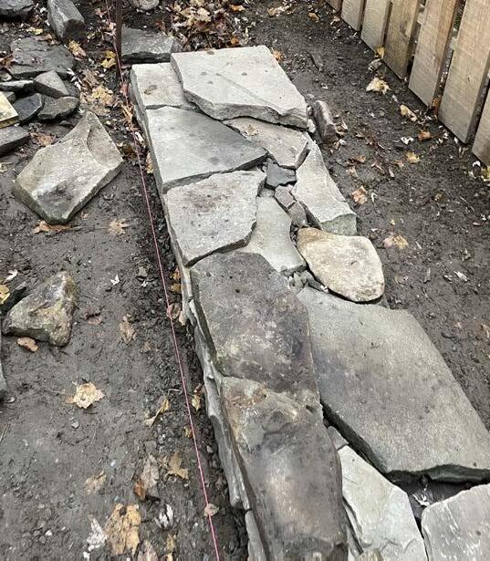
I was also happy to work with such skilled carpenters and especially the masons who formed the steps and walls shaping each stone and stacking without mortar to make something our mason promised could last 500 years!
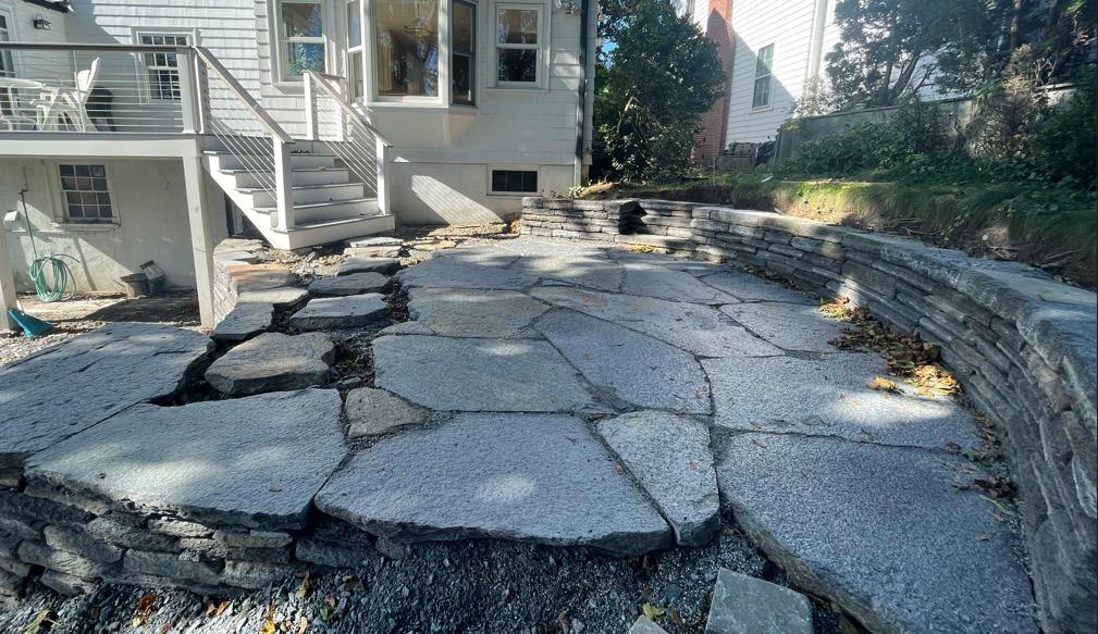

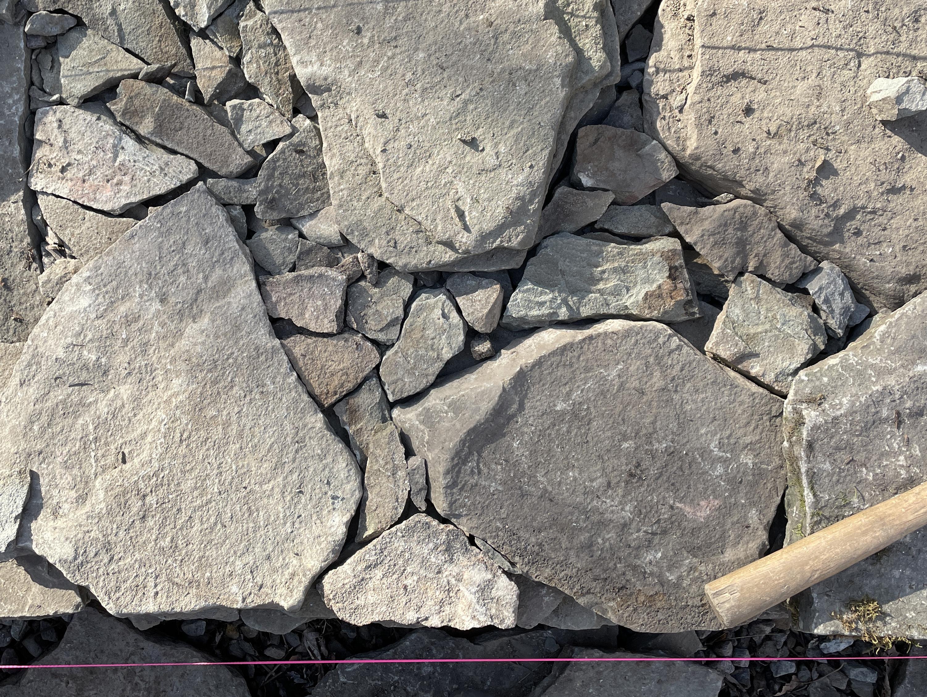
Right: The patio was built with locally sourced Goshen Stone and the seating and retaining walls were dry-stacked by expert masons
Below: Completed waterfall and planting with a stone stairway leading down to the lawn and raised garden beds
Below: Before demolition I took one last photo of the multi-level porch we were replacing,
Left: A third concept model featured a classical approach with a pergola
3D model, featured shear retaining wall and spiral stone staircase
Professional Work
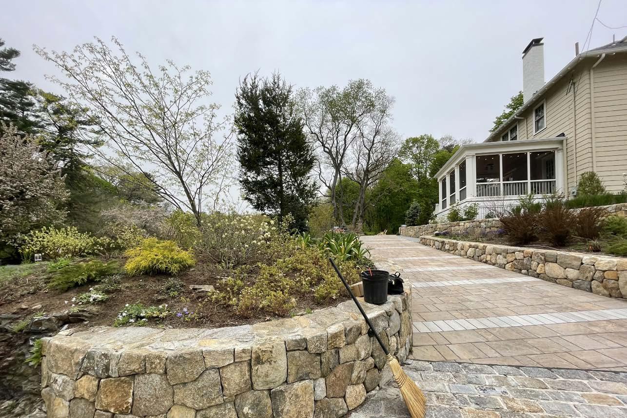
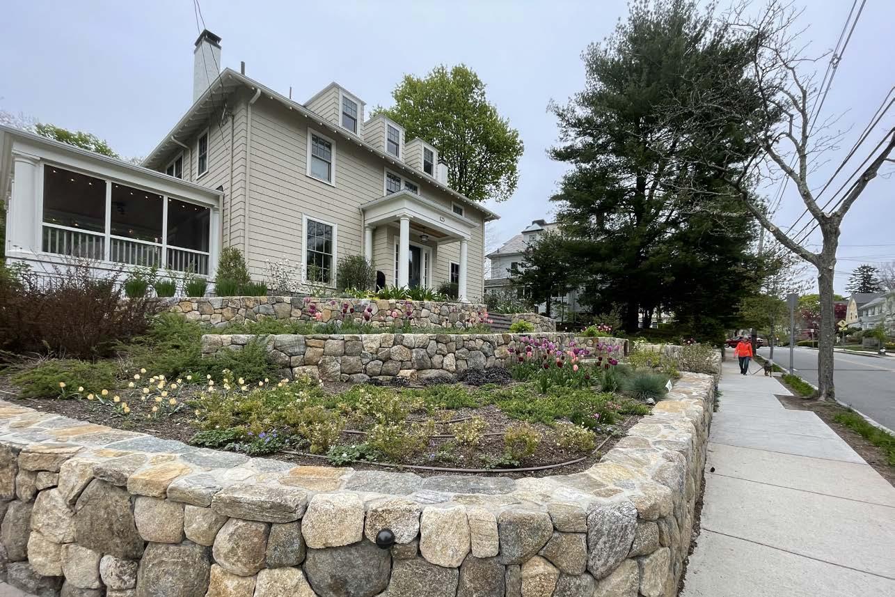
Before & After Construction
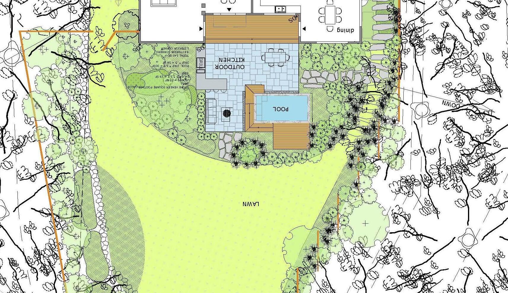
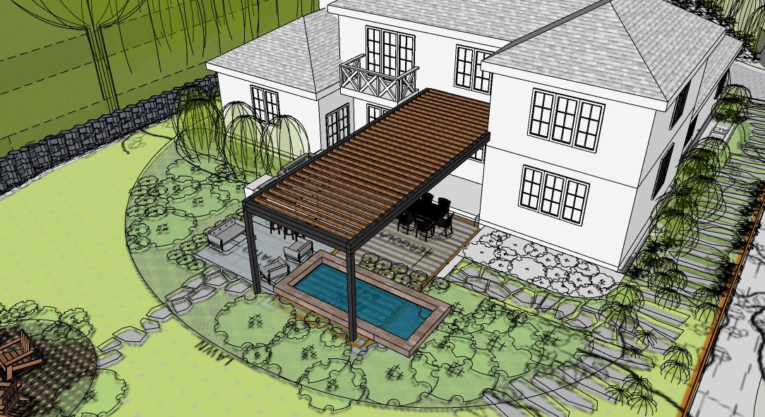
In Spring 2020, I began a project to reimagine the backyard of a suburban home perched at the edge of a steep slope. The existing landscape was overgrown and underutilized. I conducted the initial site survey and stayed involved through all phases—from schematic design to building structures and placing the final plants in the ground. Working closely with licensed landscape architects, I helped shape a layout that included an outdoor kitchen, fire table, plunge pool,


and extensive decking. I drew the framing plans for new stairs and platforms, which I coordinated directly with the carpenters on site. This project deepened my appreciation for design-build collaboration and expanded my technical skill set—reinforcing my long-term focus on architecture while grounding me in the realities of site work and landscape systems.
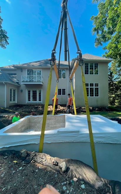
Above: The crane gently depositing the plunge pool shell and a final design
Right: The final plan featuring outdoor kitchen and plunge pool with extensive perennial planting
Professional Work
Outdoor Kitchen & Plunge Pool
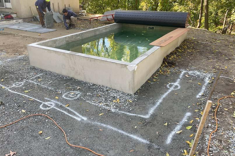
Faced with the challenge of fitting a plunge pool behind a large house with narrow site access, I researched prefabricated options and identified Soake Pools™, a New Hampshire-based company producing compact cast-concrete units. I worked with our team and their representative to coordinate placement on-site. When the pool was delivered that spring, I watched as a crane lifted it over the house and lowered it into position. After installation, I documented my supervisor’s
Perched on a steep slope, the site is at the edge of suburban development. I took part in initial Conceptualization for the clients, a pair of executives with two children, who wanted to activate their back yard space. We developed an extensive plan to build an outdoor kitchen, a fire pit, and a plunge pool built into the ground. This project was an opportunity for me to participate in early design decisions and then shift to researching how to source and build the ammenities. This was the first job on which I helped to manage the building phase as worksite team leader when the principal and assistant architect were working at other sites or in office. I got to survey the original property and draft the base existing conditions plan then work on a models and plans for a pergola that wasn’t built and a pool deck that was. It was a challenge to site our in-ground pool while adhering to codes and also take into account that the concrete shell would be lifted over the house and into place by a crane!
This was a project similar to the scope of 125 Jason Street
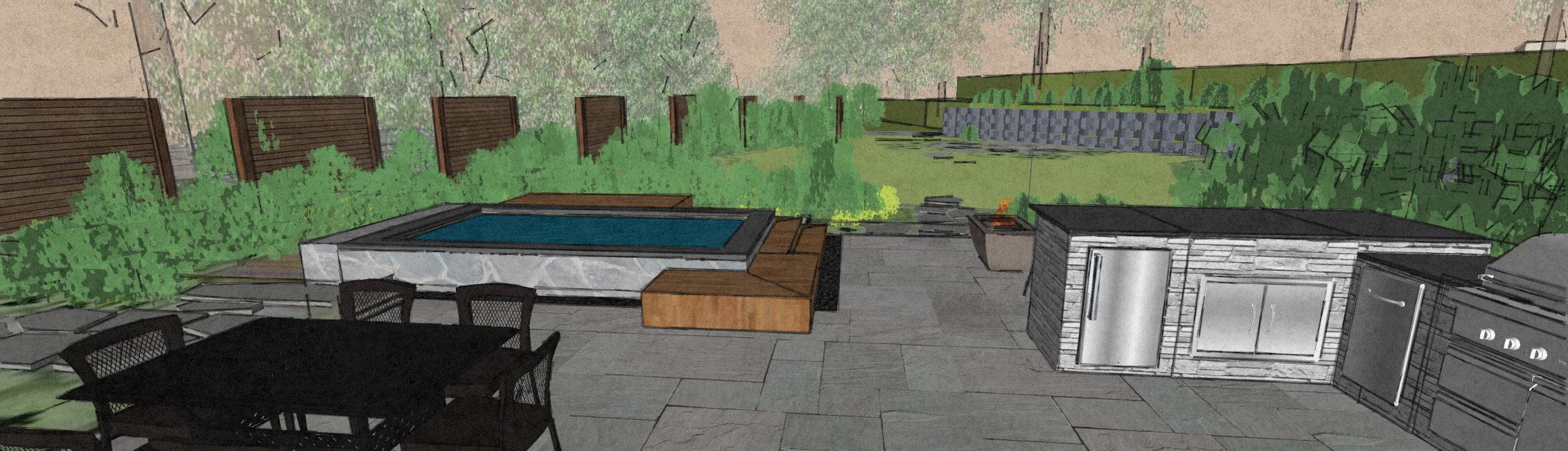
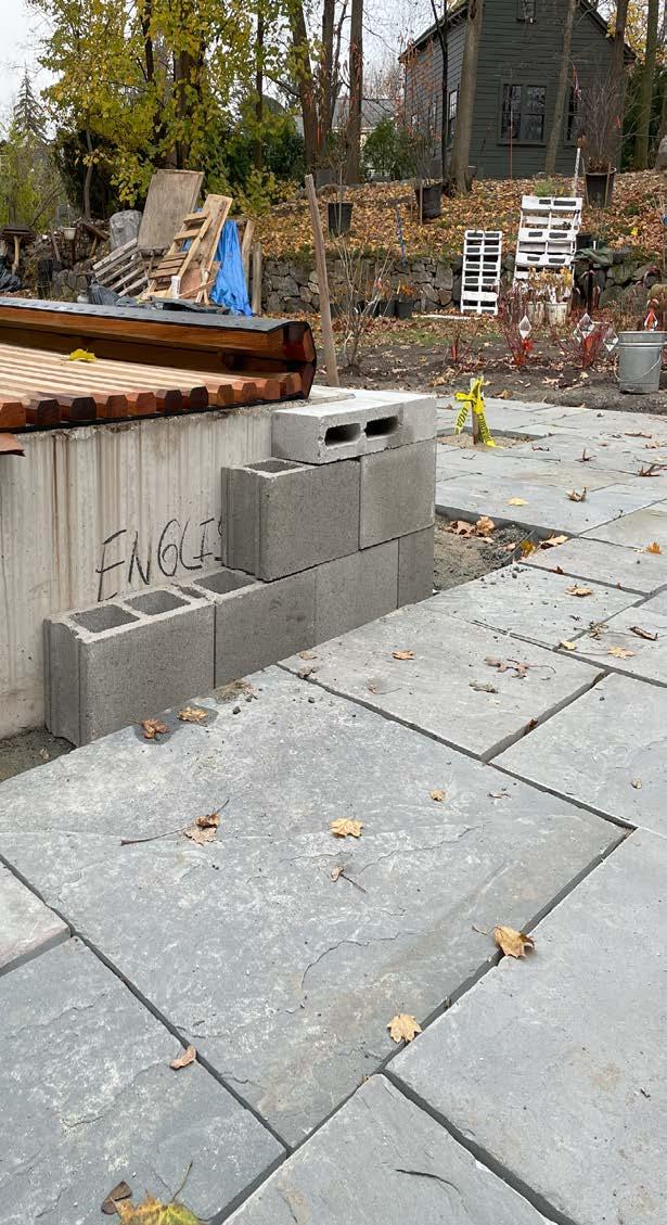
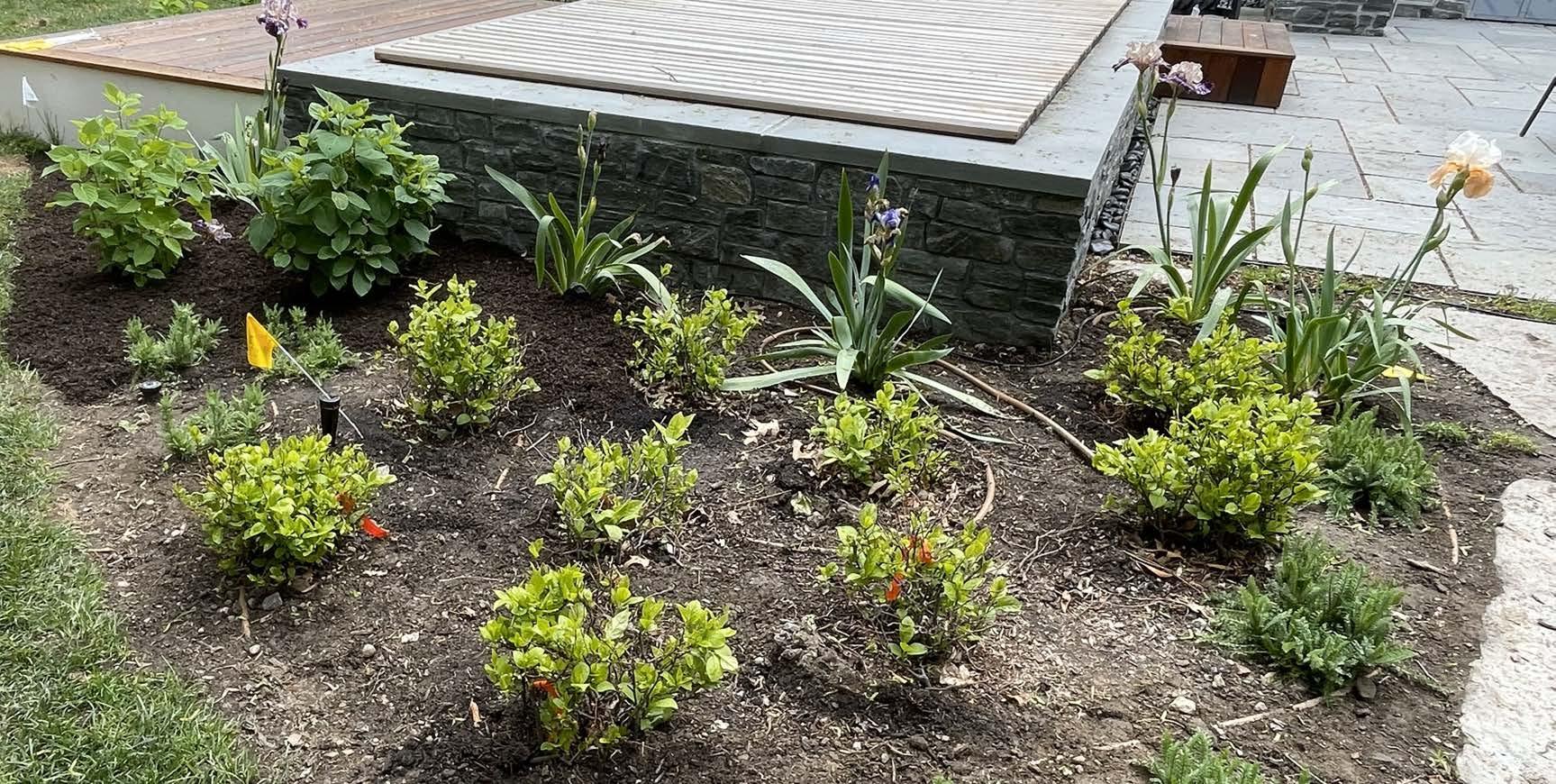
full-scale field layout—spray-painted directly on the dirt—and translated it into construction drawings for the carpenters. I then assisted in coordinating two masonry teams: one cut and set the capstone, including a challenging conduit pass-through, while the other applied veneer stone to the pool’s exterior. Once stonework was complete, we installed the surrounding bluestone patio and finalized planting around the outdoor space.
sent from Rob Gilmore to exof the plunge pool deck
gently dropiing the concrete shell of the the other side of the hosue
outdoor kitchen and plungepool in progess
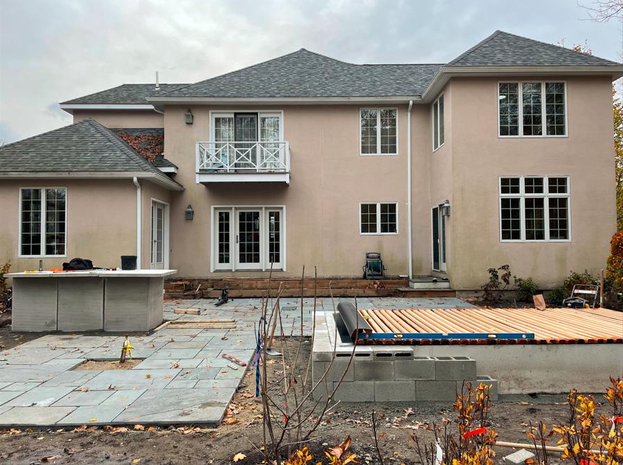
but I was on staff from the first survey to the last follow-up site visit. clients were looking for an architectural intervention in their outdoor space. I was intrigued by their desire not only for a new grill but an outdoor kitchen, not for a few chairs but an outdoor dining table and living room space with firepit; as well as an in-ground pool. Our team also suggested a pergola to unite and shelter these ammenities. I helped the clients to get excited about the idea with a Sketchup model of the pergola with views out to our team’s proposed planting plan, in 3D. I was also tasked with a framing plan for the carpenters to refer to. Unfortunately, in the design development process we learned that the cost and code limitations of a pergola over a pool would mean clients would have to chose between them and they chose the pool. It wasn’t until months later, while we were planting and carpenters working that I was asked to make a new drawing, this time, because plans had changed around the pool and the clients now wanted a deck built around it with steps and storage. I was able to go back into my model from the design development stage and a 3D model in to show the clients and a cad plan to give to the carpenters. In this case I wouldn’t classify it as a problem but a challenge of changing plans out into the building phase. I think I learned how to adapt to changing
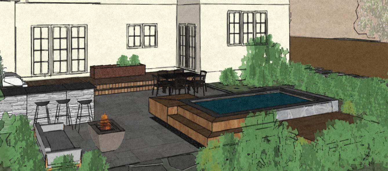
Above: Rendering of one’s view from the first step out onto the patio with all the elements in sight from a dining set to the plunge pool with steps and deck designed in-house in addition to the kitchen island which the GLA team assembled
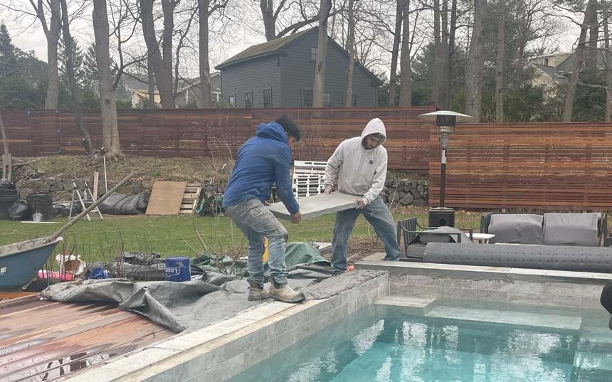
Below: We built the plunge pool in phases because part of the design could only be finalized once the concrete shell and mechanical systems for the pool were installed with the help of the team at Soake Pool.
Above Clockwise from upper left - Sketchup model drawn during construction, masons installing CMU blocks and custom cut bluestone caps, white spray paint marking dimensions for sketchup model pictured above, Final product with mahogany decking.
Below: After all construction the planting beds could be finalized and filled with flowers
Professional Work Masonry
section of
by
An informal stone reatining wall and staircase built and designed by GLA team with newly planted River Birches

My experience with masonry has been shaped by working in the field and at the drafting table. I learned by assisting more experienced builders—recording site measurements, drafting survey plans, and drawing wall sections I later saw built. That process helped me connect drawing to construction in a direct, lasting way.
Over time, I’ve worked on dry-stacked and mortared walls, permeable stone patios, and hybrid assemblies
I helped to backfill the walls, install lighting and irrigation lines, and finish with extensive planting.
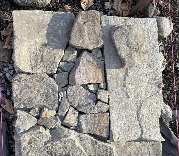
I had to precisely cut and lay down large bluestone slabs to precisely fit this patio together

like walls that double as steps or seating. I gained hands-on familiarity with brick in running bond, CMU systems, and the challenges of irregular stonework. Working alongside skilled masons gave me insight into the rhythms of craft—and the conversations needed when project intent and tradition diverge. I also got to know local masonry suppliers and developed a practical understanding of sourcing and specifying materials from both a designer’s and a builder’s perspective.
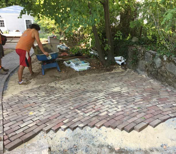
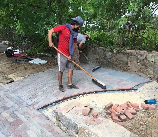
Above: On one of the more extensive projects we worked on i was able to help manage smaller projects within the larger scope. Here I was documenting the process of laying out a warped running bond made with bricks that were not uniform sizes because they were reused from a path that had previously been onsite.
Ove several project, of which this was the most recent I was able to learn how to dry stack field and flagstone walls and even though we used mortar som times the majority of the masonry I built myself was part of a slow learning process.
A
wall built
skilled masons with field stone mortared to CMU blocks.
Professional Work Carpentry
At GLA, I worked alongside skilled carpenters on a range of wood-based projects—from site-built fences and footings to schematic designs for outdoor furniture and structures. I contributed decking plans, trellis and pergola designs, and other landscape elements often referred to in the trade as site carpentry or exterior millwork.
Outdoor Furniture Concepts
T hrough this work, I developed an appreciation for how experienced carpenters think—methodically, with
Outdoor Furniture Concepts
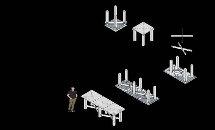
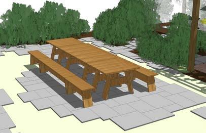
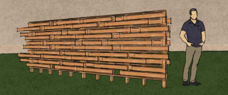
Diagrams I made with Sketchup to illustrate to my team and eventually to the clients one way the custom furniture could be dissembled for storage.
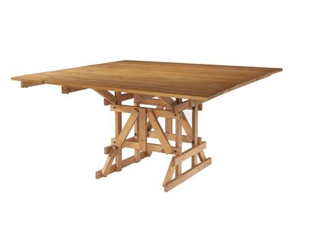
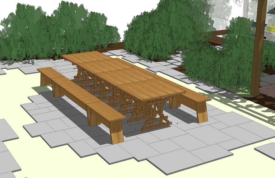

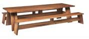
The ‘complex’ design ioption for tables and seating nspired by carpentry benches that could be dissambled for storage.
precision, and often guided more by built knowledge than formal drawings. I also became familiar with newer systems like Azek and Trex, which I’ve specified in plans and seen installed in the field.
In addition to my fieldwork, I’ve designed and drawn custom furniture pieces as a personal pursuit. I regularly use basic tools—miter saw, table saw, and drill/driver— and value carpentry for the clarity it brings to my design thinking and spatial understanding.
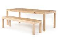
Right: A option with tables and seating that nested instead of being dissembled.

Right: the simple and elegant option made for picnic-style events
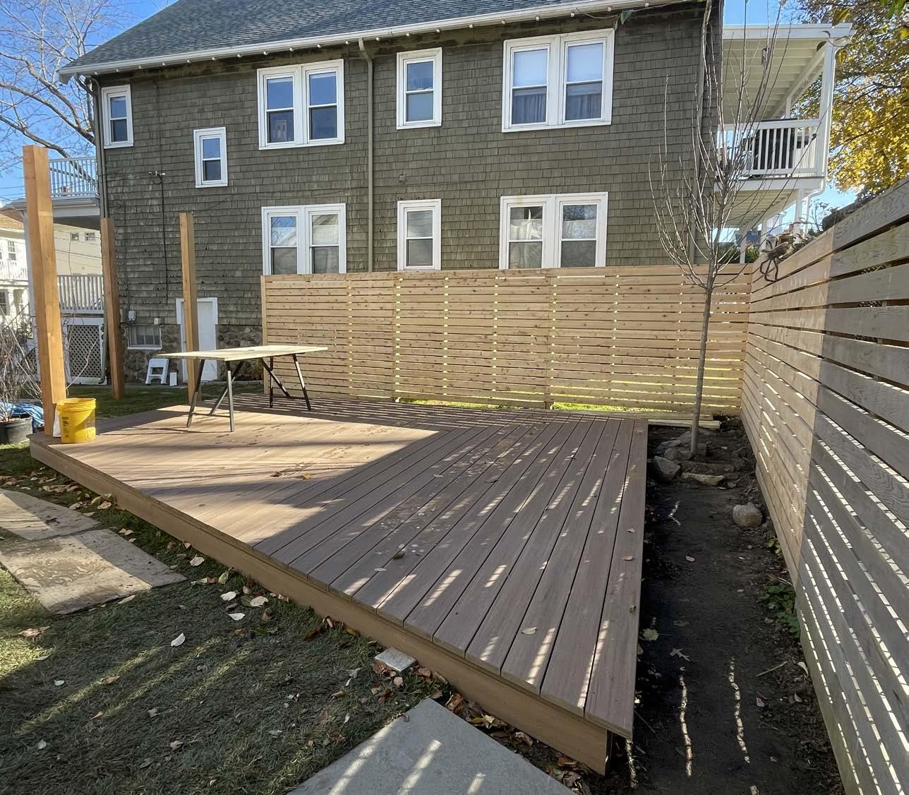
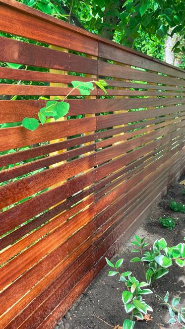
Right: Two projects with fence designs that were designed inhouse and built under my supervision onsite.
Above: A rendering of a fence design I made with Sketchup
Designer and Builder
Wild Hideaways & Public Art
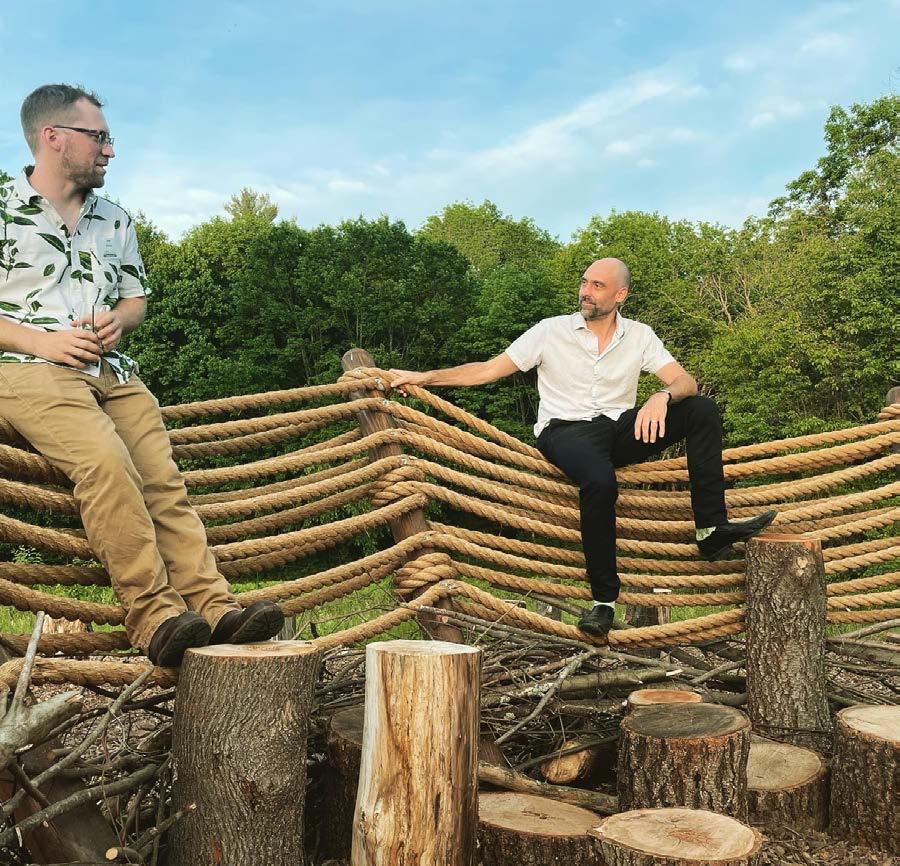
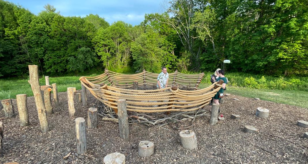
Wild Hideaways was a creative competition that GLA entered with two designs in the SPring of 2021. We were tasked with designing a temporary structure that was family-friendly and highlighted something about nature and the idea of enclosure. I joined our team of designers in a few weeks of feverish research and concept development. My final concept was not picked but my team member Fernando’s was and we got to build it!

Over the past few years, I’ve contributed to collaborative projects exploring the intersection of environment, public space, and community. At GLA, I supported the design and assembly of several temporary installations that brought landscape thinking into playful, unexpected formats. In Wild Hideaways, a design competition hosted by the Worcester Horticultural Society, our office submitted two proposals. My concept wasn’t chosen, but I contributed to planning and helped build the winning
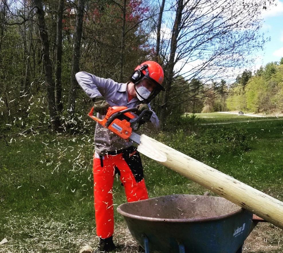
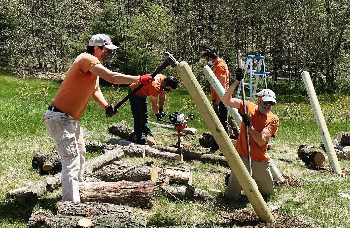
One of the most fun projects I participated in was our competition-winning entry “NEST”, built with posts cut and imbedded in the ground with heavy hemp rope tying the structure together with sticks and forest detritus found on site.
http://www.carolinaaragon.com/#/risingemotions/
http://www.carolinaaragon.com/#/risingemotions/
entry—NEST—a forest shelter made from site-sourced posts, sticks, and hemp rope.
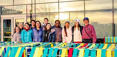
I also helped assemble two public installations led by artist and landscape architect Carolina Aragon. FutureSHORELINE marked sea level rise with colorcoded posts across the site. Rising Emotions visualized community messages on climate change using ribbons coded by tone. These projects showed me how design can prompt public reflection through material and space.
The design problem I faced was in finding a building unit that I could reconctruct into may different forms. I settled on hay bales which would have been interesting, but perhaps a bit allergenic. I overcame the block of a somewhat impracticle material and embraced my idea nonetheless, and I was able to help with more group work knowing my idea was not the best, but still worth sending.
RIGHT: For the past decade Rob Gilmore has partnered with landscape architect and artist Carolina Aragon on her site-specific interventions. I helped to assemble two of these projects. The most recent, “FutureSHORELINE” was designed to grab passersby attention show them how much higher the sea level will rise by 2070.


http://www.carolinaaragon.com/futureshoreline