SKYLINE
 DAVIS BRODY BOND, LLP MARKS BARFIELD ARCHITECTS
When we look up, it widens our horizons... in the sky, there are no boundaries.”— Julie Gregson


 DAVIS BRODY BOND, LLP MARKS BARFIELD ARCHITECTS
When we look up, it widens our horizons... in the sky, there are no boundaries.”— Julie Gregson

MARKS
What is strange to us today will be familiar tomorrow.”
— Mayor Richard J. Daley (on the unveiling of the Picasso sculpture at what is now Daley Plaza)


In early 2012 a City of Chicago Tourism Task Force commissioned a study by the Boston Consulting group (BCG) to examine how Chicago could grow visitor volumes, increase revenues, and create more employment. One of the major opportunities identified at the top the list in this study was the creation of an aerial gondola in the heart of the city.
Assets Aloft, LLC was subsequently established to develop the aerial gondola, and commissioned the preparation of a conceptual design in October 2012 led by Davis Brody Bond (DBB) and Marks Barfield Architects (MBA) with engineering advice from Jacobs and associated budget analysis by Faithful & Gould (F&G). The gondola was renamed the ‘Chicago Skyline’.
In December 2012 Assets Aloft, LLC commissioned this Feasibility Study to examine the commercial / operational viability and technical feasibility of establishing the Chicago Skyline. The Feasibility Study has been carried in two phases:
Phase l was carried out by Economics at AECOM during early 2013 and assessed the potential visitor
throughput, revenues, and overall economic viability of the Chicago Skyline Project. The Chicago Skyline Project Report addressed the Chicago Marketplace, international comparisons and evaluated the potential unconstrained and constrained demand for the Chicago Skyline. It forecasted projections of the revenues and operating costs based on the potential attendance.
Phase II of the study, presented in this document, examines and presents the findings relating to existing conditions, the environmental, regulatory and engineering context, and identifies known fatal flaws which would prevent moving forward with the project. This study analyzes the design concept for the Chicago Skyline prepared by DBB and MBA, incorporating engineering advice from Jacobs and specialist advice from Leitner-Poma of America (LPOA)
DBB and MBA, assisted by Jacobs, LPOA and others, have continued to develop the preschematic architectural design of the proposal during the technical feasibility and operational viability study period.
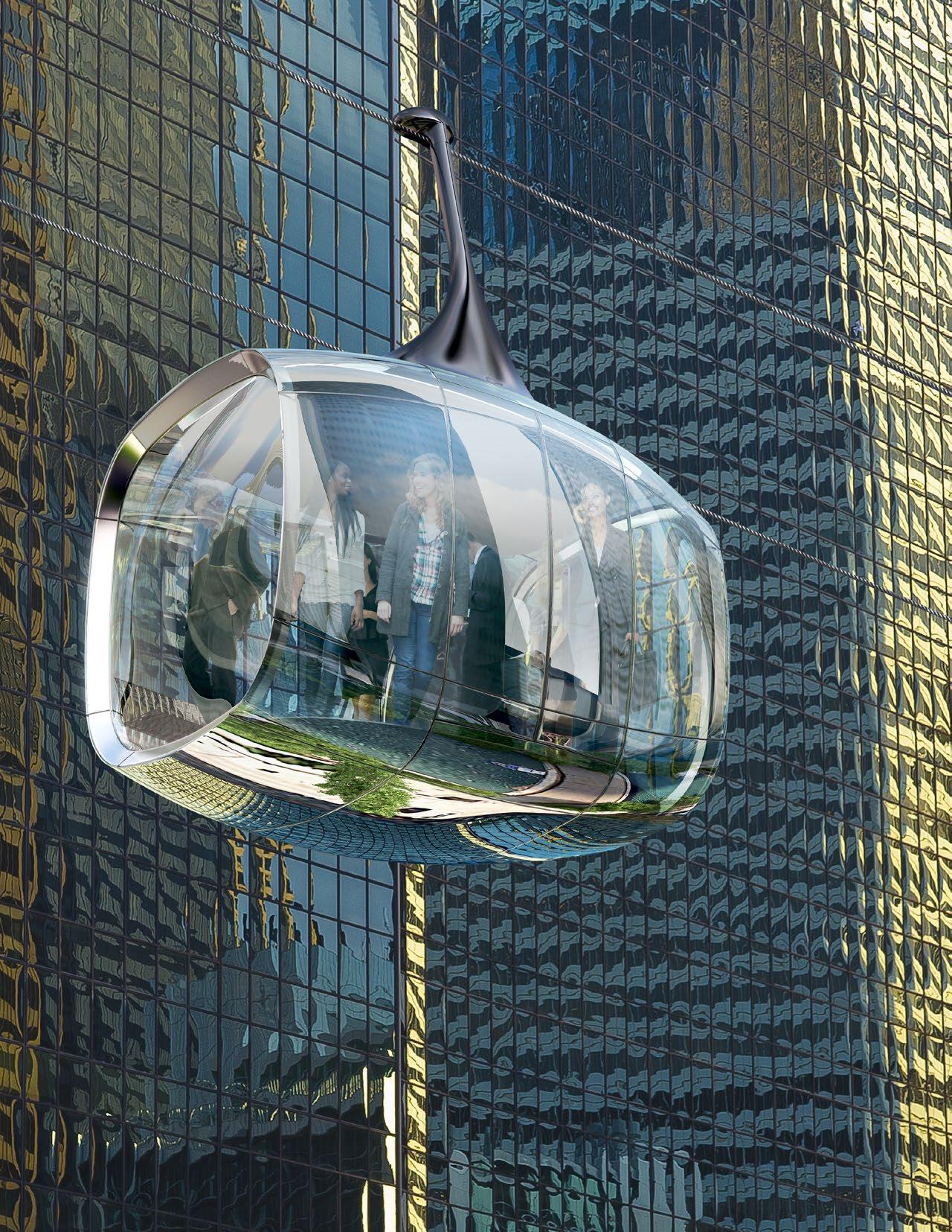
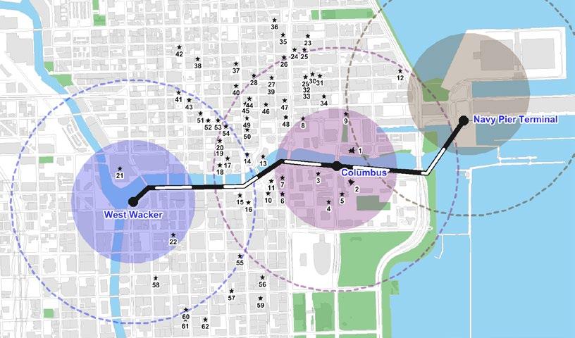
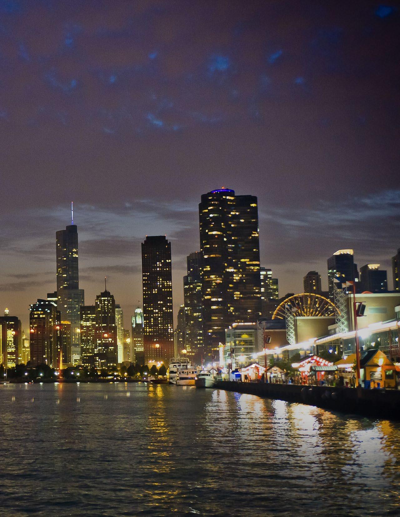
The Chicago Skyline would be a new 1.6 mile aerial cable car tourist attraction and urban transport proposal linking Navy Pier, the Chicago River waterfront, and downtown Chicago. (Figure 1-1). A pedestrian link to Union and Ogilvie Stations will be evaluated in a future phase.
The principal features of the design concept are as follows:
• The proposed route would connect Navy Pier with a site adjacent to 333 W. Wacker Drive and run along the southern side of the Chicago River.
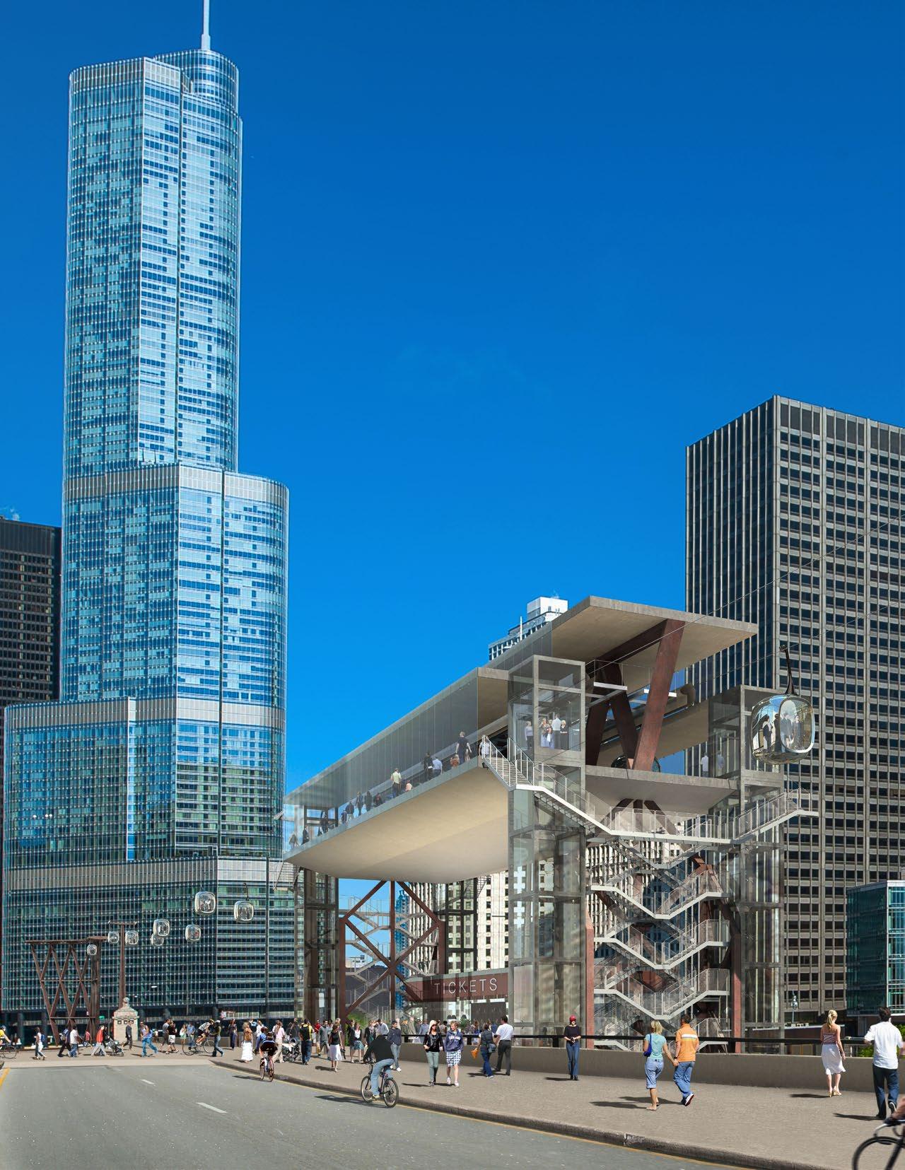
• There would be two terminus stations for passengers: one within Gateway Park to serve Navy Pier, and one at West Wacker located between Lake Street Bridge and Franklin Street Bridge.
• There would be one intermediate station for passengers located at Columbus Drive adjoining Wacker Drive, which would serve as the corridor to Millennium Park. Columbus Station would house the system’s electrical drive motors.
• Between Columbus and Lake Shore Dr. Bridges there would be a garage structure to accommodate the gondolas or ‘pods’ when out of service.
• The cable system would be supported by ten vertical tapering pylons of various heights along its route, a bifurcated pylon at Gateway Park terminus and a trifurcated pylon at West Wacker terminus, which provide the necessary vertical clearance above the opening bascule bridges over the Chicago River. The system would be designed to avoid restricting navigation on the Chicago River.
• In order to negotiate the bends in the River and to cross the River mouth there would be four transfer structures that would allow the Skyline to change direction (i.e., not travel in a straight line). There would be one transfer structure in the northeast corner of Grant Park in the vicinity of DuSable Harbor; and three in the Riverwalk, one between Michigan Avenue Bridge and Wabash Street Bridge, one between Wabash Sreet Bridge and State Street Bridge; and one between Franklin Street Bridge and Lake Street Bridge.
EAST WACKER DRIVE
ROOM 5
ROOM 4
W3 W4 W5 W6 W7 E5 W1 W2
WEST WACKER TERMINAL STATION 48’/28’-5”
CHICAGO
FRANKLIN ST. WELLS ST. LASALLE ST. CLARK ST. STATE ST. WABASH AVE. MICHIGAN AVE.
EDGE OF FUTURE RIVERWALK 50’ FROM RIVER WALL
ROUTE DATA
Route Length 1.6 miles
Vertical Pylons 10
Bifurcated Pylons 1
Trifurcated Pylons 1
Transfer Structures 4
Pods (in garage) 120
#Passengers / pod 12
DEARBORN ST.
WABASH AVENUE TRANSFER STRUCTURE 75’/47”
MICHIGAN AVENUE TRANSFER STRUCTURE 143’/105’
Pod Speed 60’ / min. in station; 800’ /min abv. station
PRITZKER PAVILLION
COLUMBUS DRIVE STATION 125’/70’

PARK
LAKE
NOTES
• “Rooms 1-6” refer to naming conventions provided by CDOT for areas of development that appear between bridges and are associated with the Chicago Riverwalk.
• All heights based on the design team’s current engineering strategy and measured from Riverwalk & Upper Wacker levels, respectively.
• Transfer Structure design development is in currently in progress and two options have been presented for client review.
• Close coordination w/ site conditions follows in next design phase. Required demolition has not been quantified at this time. Existing utility contiditions to be further verified.
 Figure 1-1



• The gondolas (pods) will be of innovative design and will have a capacity of up to 12 people in each. Based on the projected demand, the system will be designed to carry up to 3,375 people per hour at 900 feet/minute (4.57 m/sec in each direction).
• The Chicago Department of Transportation (CDOT) is planning to extend the Riverwalk west of State Street Bridge as far as Lake Street Bridge. Therefore the relevant structures need to be coordinated with the Riverwalk extension.
Chicago draws over 46 million visitors annually and has a number of very popular visitor attractions that appeal to residents and tourists alike. The most visited attraction in the city is Navy Pier which provides a range of different attractions and is free to access, attracting over 8 million visitors per year. There are two potential visitor segments available for the Chicago Skyline, regional daytrip residents and overnight tourists. Approximately 60% of the nearly 46 million annual visitors to Chicago stay overnight, with the remainder visiting on a day trip. There is also the potential to draw passengers from the commuter market. These are reviewed in detail in the Chicago Skyline Project Report.
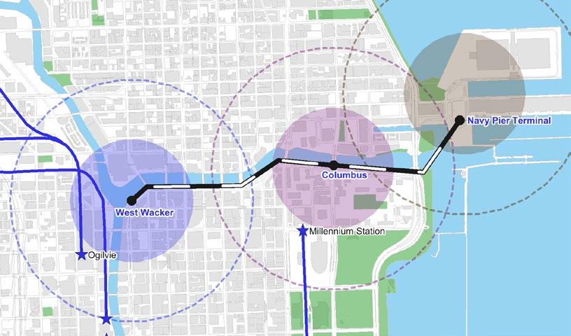
The Chicago Skyline route and alignment has been assessed and selected to minimize disruption, maximize accessibility, and maximize the opportunity to draw passengers from the available markets. The route is in close proximity to hotels, Metra commuter rail terminals,CTA rail stations and bus routes, tourist bus routes, river boat services, and the new Chicago Bike Share system known as ‘Divvy’ (Fig. 1-2 to 1-10).
A one-way trip from West Wacker to Navy Pier will take approximately 15 minutes and a round trip 30 minutes, a similar length of time as a ride on the London Eye. The pods will travel at approximately 900 feet per minute (4.57 m/s) between stations and approximately 60 feet per minute (0.3 m/s) in the passenger stations in order to allow people to safely board and alight, a similar boarding and disembarkation speed to the London Eye.

The design and construction team behind the Chicago Skyline includes key people and firms who originated, built and managed the UK’s number one paid for visitor attraction, the London Eye. They bring with them a wealth of experience from that project.
The originators and designers of the London Eye are husband and wife team, David Marks and Julia Barfield of Marks Barfield Architects (Marks Barfield). David and Julia founded the London Eye Company (LEC), acquired the site, obtained planning consent, and raised the capital necessary to build the observation wheel. They were non-executive directors and one third shareholders of LEC until they sold their interest to the Tussauds Group (now part of Merlin Entertainments) in February 2006.
The idea of the London Eye originated in 1993 in response to calls in the national press for ideas to celebrate the millennium. In 1994 David and Julia formed the London Eye Company. In 1995 the Company became a joint venture with British Airways with David Marks as Managing Director. A suitable site was secured, and planning permission granted in 1996. In 1997 the Tussauds Group was appointed as the operators. Financing was concluded in October 1998 and the London Eye opened to public acclaim in 2000. Since then, the London Eye has become the most popular paid-for attraction in the UK. David and Julia continued as directors of the London Eye Company throughout the first six years of operation until they sold their one-third interest to the Tussauds Group in February 2006. David and Julia were awarded MBEs in The Queen’s New Year’s Honours List 2000, and have received The Prince Philip Special Commendation for Outstanding Achievement in Design for Business and Society. Both are Fellows of the Royal Society of Arts.
The London Eye was an extremely profitable venture delivering an excellent return on investment to its shareholders and wider economic benefits to the local community and city. The team behind the Chicago Skyline comes with the benefit of the experience of the lessons learnt from the London Eye and has planned the Chicago Skyline to minimise the risks and maximise the social, environmental and financial returns. The passengercarrying pods, ride and and drive systems will be manufactured by Leitner-Poma, who built the London Eye capsules. The engineering design has been developed with Jacobs, who are the London Eye’s principle engineers.

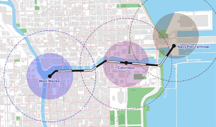


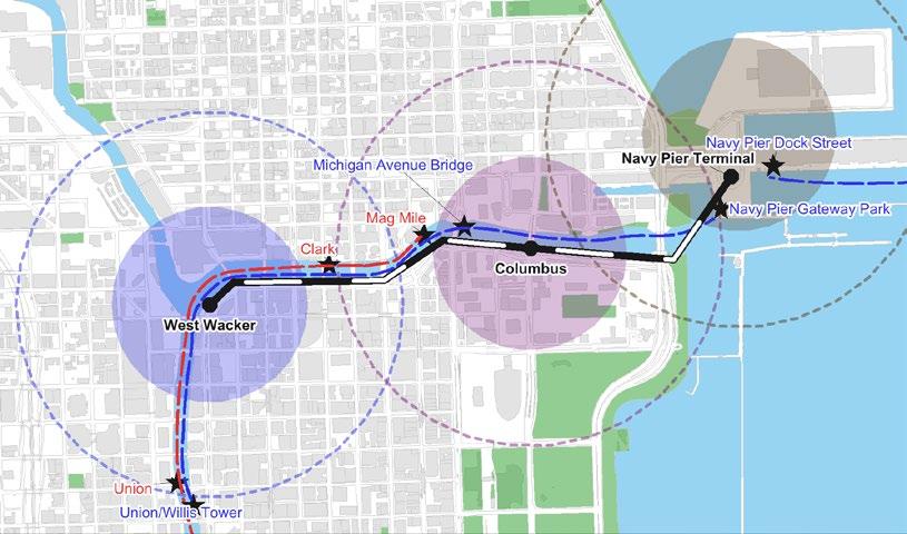

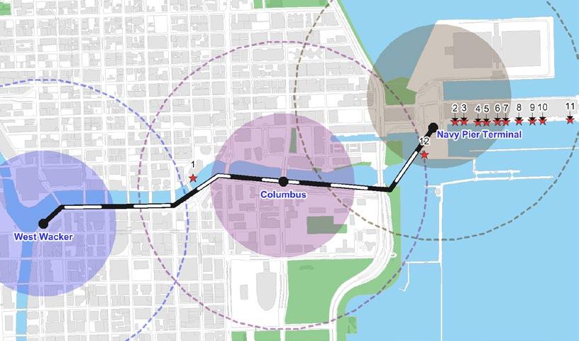


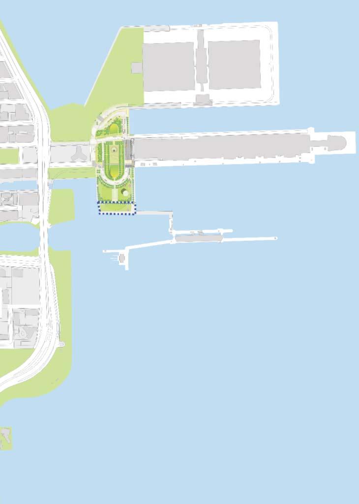

 Figure 1-11a
Three aerial alignments were considered (Figure 1-11):
A. Above the Chicago River
B. Above Wacker Drive
C. Above the Existing and Planned Riverwalk
A. Above the Chicago River
There are three significant issues with an alignment over the Chicago River along the full length of the proposed route. Firstly, this approach would require pylons in the river and stations above the river which would need to be designed to prevent or withstand possible ship impact. Secondly, it would impede river traffic. Thirdly, the route would have to be sufficiently elevated to avoid conflict with the open leaves of the bascule bridges. Therefore, the option has not been considered further.
B. Above Wacker Drive
The principal issue with an alignment over Wacker Drive is that the roadway is a post tensioned reinforced concrete deck construction and would require major construction in order to locate foundations for the stations and pylons. Reconstructing Wacker Drive, a ten-year old roadway structure, is not financially viable as part of this project. Therefore, this option has not been considered further.
C. Above the Existing & Planned Riverwalk
An alignment over the existing and planned Riverwalk avoids these issues, and would be sited such that locations for the stations, pylons, and foundations minimize impacts on underground services / infrastructure, pedestrian access, existing and planned uses, and public enjoyment of the Riverwalk. The alignment would also be carefully sited in order to avoid conflict with the opening of the bascule bridges (Figure 1-12, pp. 18-19).
The planned route would run over public land and the Chicago River, and has been designed to provide a unique visitor attraction within the city, complementing the range of existing offers and helping to raise Chicago’s global profile. This is considered to be the optimum route given the existing demand assumptions which are explained in the Chicago Skyline Project Report.
In order to deliver a 30-minute round trip (15 minutes terminal to terminal) and accommodate the projected demand forecast as set out in the Chicago Skyline Pre-Schematic Report, it was calculated that the system be designed to provide an operational capacity of 3,000 passengers per hour (pph) using an 80 per cent load rate to allow for family groups, travelling at an operating speed of 800ft/min. This is referred to as the normal ‘design’ speed and capacity, i.e. the speed and capacity at which the system will normally run to meet projected demand at peak periods. This requires 120 twelve-person capacity pods.
The Owner has requested that maximum specified capacity and operating speed be increased to accommodate potential demand beyond that forecast in the Chicago Skyline Pre-Schematic Report. The maximum specified speed has been set at 900 ft. per minute, generating a maximum theoretical capacity of 3,375 pph. This is referred to as the ‘specified’ speed and capacity, i.e. the speed and capacity at which the system will run to meet unusual demand over and above ‘design’ peak periods.
It is not expected that the ride will normally operate at 900 ft. per minute, as this would reduce the round trip to under 20 minutes and may affect the quality of the experience, as well as perception of the value for money of the ticket price. However, as a contingency measure to deal with, for example, unusually large numbers of people exiting an event at Navy Pier and wishing to travel downtown on the Skyline, the operator would be able to increase the system speed and hence its capacity.
The specified, or increased, speed and capacity has been taken into account in determining the length of the boarding and disembarkation platforms in the Passenger Stations as well as the required length of the transfer structures but not in the calculated capacity and design of the passenger elevators.


The Chicago Riverwalk Project is a $110 million project to expand and enhance the Chicago Riverwalk all the way from State Street to the intersection of Wacker Drive and Lake Street. This project involves the extension of the river wall 25 feet into the river (expanding to 50 feet into the river between Franklin Street and Lake Street), creating a riverside walkway with gardens, restaurants, retail outlets, a possible wading pool area, and other facilities to encourage people to make greater use of the river. CDOT has taken necessary measures to redefine the navigable waterway on the Chicago River in order to allow the extension of the river wall.
The Chicago Skyline will follow the Riverwalk and there will be opportunities for strong links between the Riverwalk and the Skyline at the stations planned along the route at Columbus Drive and West Wacker Drive.
Like the London Eye on London’s South Bank, the Chicago Skyline will draw large numbers of people to the Riverwalk where they can enjoy the spectacle, meet friends, or simply go for a stroll by the water’s edge.
Four potential sites were studied for this station (see Figure 1-13):
A. ‘City Steps’ option
B. ‘Public Art’ option
C. ‘CTA Bus Terminal’ option
D. ‘South Lawn Welcome Pavilion’ option
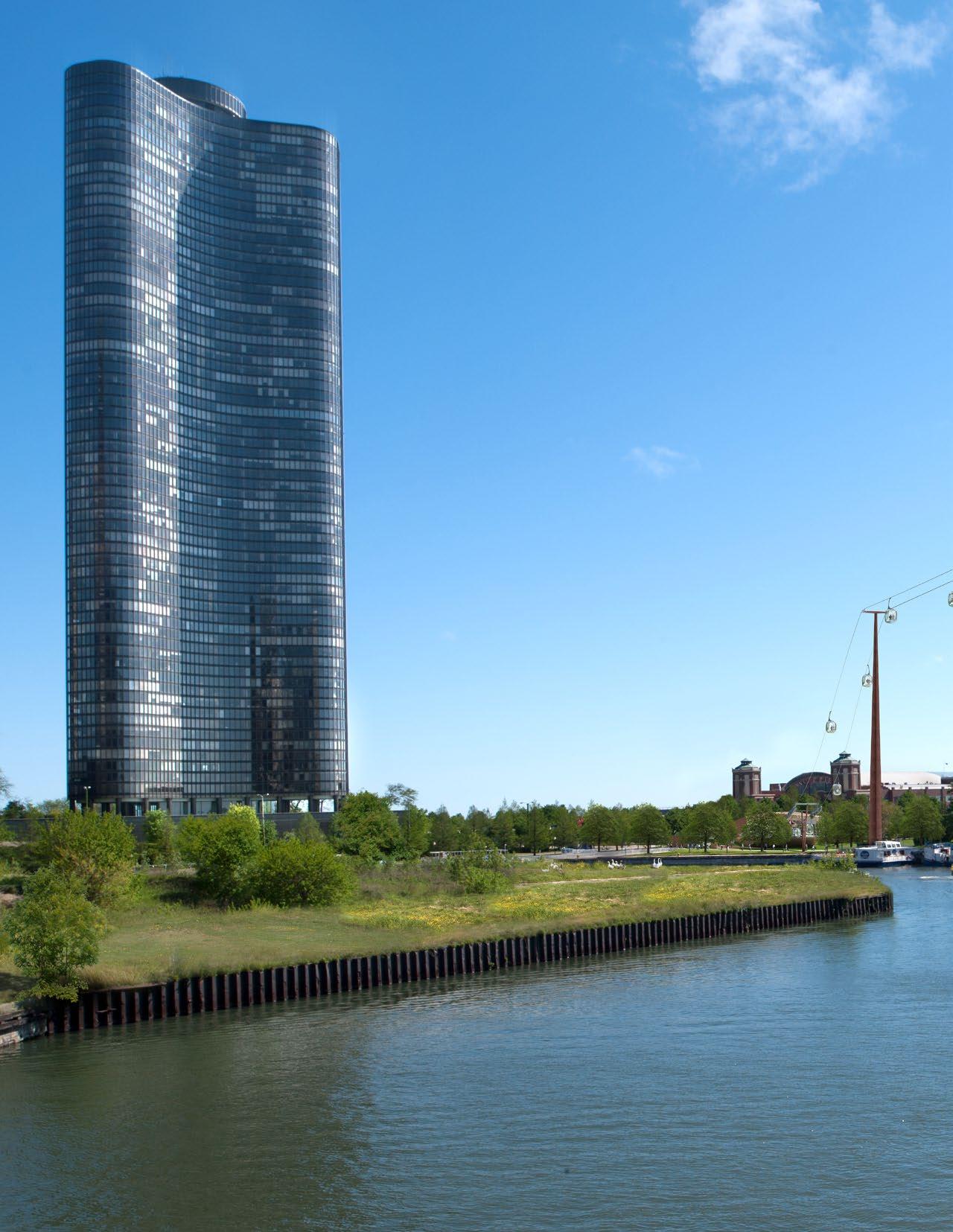
The City Steps option (Figure 1-13) would require a pylon to be erected in the river in order to achieve an acceptable angle of inclination for the podcarrying cables and reach the federally required clearance of 120 feet over the Chicago River mouth. This pylon would need to be designed and protected from possible ship impact. It would also create an obstruction to navigation. The alignment would cross the United States Coast Guard (USCG) ‘protected area’ and raise a question mark over any maintenance or evacuation that may be required over this area.
The Public Art option (Figure 1-14) would also cross the USCG ‘protected area’ and raises questions over any maintenance or evacuation that may be required over this area. In practice, it also has difficulties as a result of space constraints on site.
The CTA Bus Terminal option (Figure 1-15) would avoid crossing the USCG ‘protected area’ and does not require a pylon in the river. However, this alignment would increase the span across the river. The proposed alignment would also cross over the planned Central Plaza Interactive Water Feature between Lake Point Tower and Navy Pier Headhouse, a Chicago City Landmark.
The South Lawn Welcome Pavilion option (Figure 1-16) avoids crossing the USCG ‘protected area’, would not require a pylon in the river, and would have a more reasonable span across the river. It would have the advantage of delivering people directly onto Gateway Promenade, the pedestrian walk leading directly to the pier. This option is supported by James Corner Field Operations, designers of Gateway Park, and would be capable of accommodating the program originally proposed for the Welcome Pavilion, including a Divvy bike share station. This location also leaves open the possibility of extending to the east end of Navy Pier.This station location was therefore advanced as part of the system design.


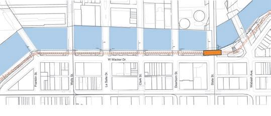


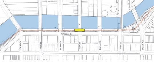
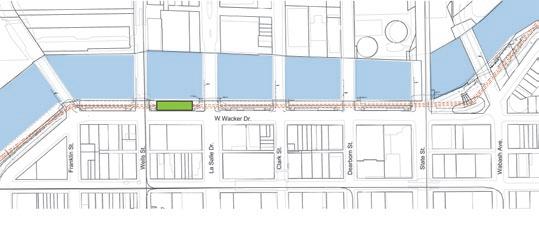
This is the first potential ‘downtown’ station location after crossing the Chicago River from Gateway Park / Navy Pier. Three potential sites were studied for this station (see Figure 1-14):
A. On the Riverwalk mid-way between Lake Shore Drive and Columbus Drive
B. On the Riverwalk east of Columbus Drive
C. Directly above Columbus Drive Bridge, spanning the roadway
A. On the Riverwalk mid-way between Lake Shore Drive and Columbus Drive
Siting the station between Lake Shore Drive and Columbus Drive would result in a conflict with the vehicular up-ramp onto Upper Wacker Drive, due to the geometry and of the alignment of the route, the cable gauge (the distance between the haul cables carrying the pods), and the required width of the boarding and alighting platforms. It would also occupy a significant amount of land and create an obstruction at the Riverwalk level opposite the Melas Fountain, an iconic water cannon fountain that shoots a huge arc of water across the river for 10 minutes every hour on the hour. Consequently this option has not been considered further.
B. On the Riverwalk east of Columbus Drive
Siting the station on the Riverwalk immediately to the east of Columbus Drive, where the Riverwalk is slightly wider, would also occupy a significant amount of land on the Riverwalk due to the combined footprint of the station and the associated pod Garage. The Garage would be larger at this location due to the requirement of a more complex conveyor system. There is also evidence of plans for future development at this location. However, the location is currently being priced and considered as an alternate.
C. Directly above Columbus Drive Bridge, spanning the roadway
Siting the station directly above Columbus Drive Bridge, spanning the south abutments of the bridge, would minimize the impact on the Riverwalk as the station would effectively be above the vehicular roadway. This site is ideally located in terms of visibility, proximity to hotels on the
Columbus Drive corridor, and access to Millennium Park. This station location was advanced as part of the system design.
A number of alternative options were considered regarding a potential station at or near the junction of State Street and Wacker Drive, being the nearest ‘viable’ location to Michigan Avenue (see Figure 1-15):
A. Between Dearborn Street and State Street
B. Directly above State Street Bridge, spanning the roadway
C. Directly above Clark Street Bridge, spanning the roadway
D. Between Wabash Avenue and State Street
E. No station here, with a terminus sited between Wells Street and Lasalle Drive
F. No station here, with a terminus sited at W. Wacker Drive
There are a number of and varying degrees of constraints, issues, and opportunities associated with the above-mentioned options. They include:
• Height / visual impact
• Impact on the existing / planned Riverwalk extension
• Accessibility / proximity to Michigan Avenue
• Cost
A. Between Dearborn Street and State Street
Siting the station between Dearborn Street and State Street would result in a significant impact on the planned Riverwalk ‘Marina Plaza (Room 1)’ which is already 90% designed and due for construction at the end of 2013. This option has therefore not been considered further.
B. Directly above State Street Bridge, spanning the roadway
Siting the station directly above State Street Bridge, spanning the south abutments of the bridge, would have less impact on the Riverwalk as the station would effectively be above the vehicular roadway. This site is ideally located in terms of visibility and proximity to Michigan Avenue, and ‘reflects’ the ‘L’ station one block away at State and Lake. However, it would require


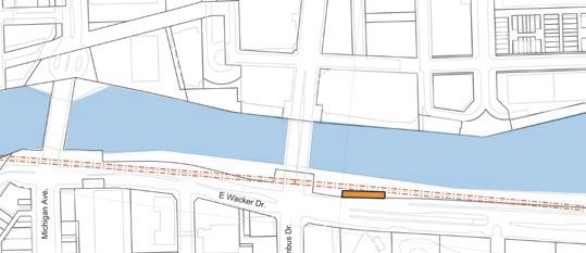
a very elevated station in order to provide safe clearance over the opening bascule bridge. This option has therefore not been considered further.
C. Directly above Clark Street Bridge, spanning the roadway
Siting the station directly above Clark Street Bridge, spanning the south abutments of the bridge, would also have less impact on the Riverwalk as the station would effectively be above the vehicular roadway. The height of the station would be similar to that at State Street Station in order to provide safe clearance over the opening bascule bridge, and being even further from Michigan Avenue, this option has not been considered further.
D. Between Wabash Avenue and State Street
Siting the station between Wabash Avenue and State Street on the ‘angle’ would have significant impact on the existing Riverwalk and the Vietnam War memorial as a result of the vertical transportation requirements to access the boarding and alighting platforms which would have to be incorporated at this sensitive location. This option has therefore not been considered further.
E. No station here, with a terminus sited between Wells Street and Lasalle Drive
Siting no station here, with a terminus station between Wells Street and LaSalle Drive would have a significant impact on preliminary designs for Riverwalk Room no. 4. It would also increase the distance of the terminus from Ogilvie and Union Stations (farther than the comfortable half-mile walk). This option has therefore not been considered further.
F. No station here, with a terminus sited at West. Wacker Drive
Siting no station here, with a terminus station at West Wacker Drive, between Franklin Street Bridge and Lake Street Bridge, is the preferred option for the following reasons:
• West Wacker Drive is adjacent to the widest part of the River with a maximum 50 ft wide build-out from Lower Wacker Drive
• West Wacker Drive is the termination of the Riverwalk, thus any impact on the Riverwalk would be minimized
• West Wacker Dr. is currently the closest currently feasible location to Ogilvy & Union Stations.
• There is no demonstrable commercial business case for a station at or near State Street.
• Closest points of access to the Skyline at or near State Street, given stations at West Wacker Drive and Columbus Drive, are within 10-min. walking distance (a reasonable distance for a tourist to travel). Consequently, there would be little impact on market penetration rates for the Skyline given the absence of a station here
• If a station were to be provided at State Street, an additional conveyor system would need to be installed to maintain a comfortable user experience, i.e. pod speed
• Certain conflict at War Memorial
No station at or near State Street, with a terminal station at West Wacker Drive between Franklin Street Bridge and Lake Street Bridge, was advanced as part of the system design.
This would be the closest station to the two largest downtown commuter rail stations at Ogilvie Transportation Center and Union Station, which are both roughly a half-mile away. Two potential alternatives were examined for this station (see Figure 1-16):
A. Approximately centrally located between Lake Street and Franklin Street.
B. Immediately northeast of Lake Street Bridge.
A. Approximately centrally located between Lake Street and Franklin Street
Siting the station approximately centrally between Lake Street and Franklin Street would require a conveyor system and attendant support structure to transport the pods from the angle station above Franklin Street Bridge down to the station, due to the angle of inclination. The addition of this visual impact consisting of motor, structure and their constituent components is not ideal.
B. Immediately northeast of Lake Street Bridge
Siting the station immediately northeast of Lake Street Bridge at the westernmost point of the planned Riverwalk would allow any pedestrian ramp to be located between the station and
VARIES FROM 105’ TO 185’ MAX

The vertical route, Park Wacker
The clearance over tapering very thicknesses the thickness It ‘perforations’ increase lightness varying studied design
Franklin Bridge, where it would connect directly to the planned Riverwalk. This location also reduced the risk of “dead space” southwest of the station at mid-block, helping to create more lively Riverwalk configurations to the north and east. This location was advanced as part of the system design. This station would be designed and built within the planned Riverwalk and integrated within the Riverwalk extension.
Approximately 120 pods would need to be stored in a garage. Three potential sites were studied (Figure 1-17):
A. Gateway Park / Navy Pier
B. Adjacent to Lower Wacker Drive between Lake Street and Franklin Street
C. On the Riverwalk between Lake Shore Drive and Columbus Drive.
A. Gateway Park / Navy Pier
Locating the garage in Gateway Park would occupy much more space than the station alone, creating a larger impact on the available open space. Locating the garage underground was considered, but the garage would be below the water table and therefore be susceptible to flooding. This option has not been considered further.
B. Adjacent to Lower Wacker Drive between Lake Street and Franklin Street
The area below West Wacker (between Lake Street and Franklin Street) appeared to be available and surplus to vehicular requirements. However, on examination it was found that the available height in this location is not adequate to accommodate the pod with attendant hanger and conveyor rail system. This option has not been considered further.
C. On the Riverwalk between Lake Shore Drive and Columbus Drive.
The site on the Riverwalk between Lake Shore Drive and Columbus Drive, previously considered for Columbus Station, where Wacker Drive consists of a three-level thoroughfare, would meet the required design criteria and potentially allow maintenance access to the location from the lower level of Wacker Drive. This site appears to
be the best option, particularly if the garage structure is designed to minimize the impact on the Riverwalk. This option was advanced as part of the system design.
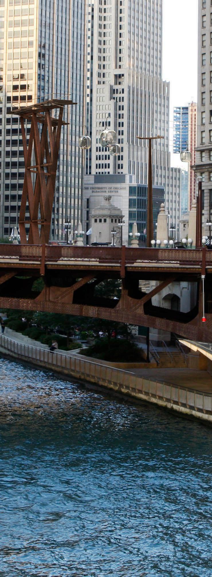
The cable system would be supported by ten vertical tapering pylons of various heights along its route, together with a bifurcated pylon at Gateway Park terminus and a trifurcated pylon at West Wacker terminus (see Figure 1-18). These ensure the necessary vertical clearance for the route above the opening bascule bridges over the Chicago River (see Figure 1-12). The pylons are designed as tapering plate-steel cruciform sections which are very simple and easy to fabricate and erect. Plate thicknesses vary from 3 ½ inches (90mm) at the base for the tallest pylon (197 feet or 60m) to 1 ¼ inches (30mm) plate thickness at the top.
In order to negotiate the bends in the River and to cross the River mouth there would be four transfer structures that would allow the Skyline to change direction — that is, not travel in a straight line (see Figures 1-19 to 1-22). The transfer structures are located as follows:
• In the northeast corner of Grant Park
• On the Riverwalk immediately to the west of Michigan Avenue
• On the Riverwalk immediately to the east of State Street
• On the Riverwalk spanning the Franklin Street Bridge at the south abutment.
The transfer structures are of varying heights between 75’ and 185’ above Riverwalk level. The location of the two transfer structures between Michigan Avenue and State Street requires careful consideration in order to minimize any impacts. The lack of landing area at Michigan Avenue and the existing Vietnam War Memorial at State Street both present mitigating circumstances.
High level catwalks will be provided to access and maintain the pod conveyor system through the structure. There will be no passenger boarding or alighting at the transfer structures.


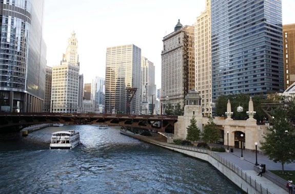
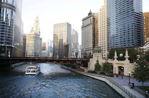

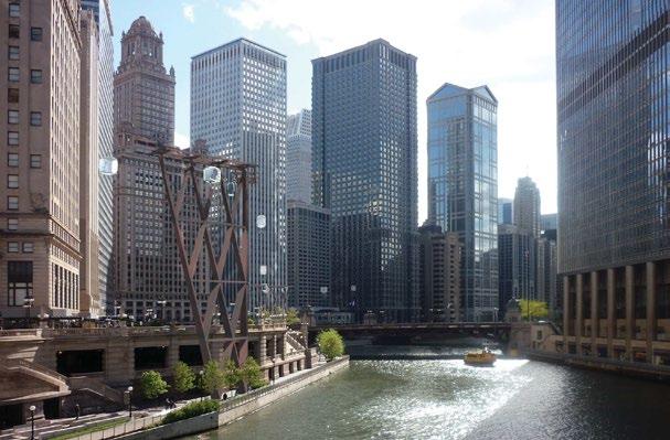 Figure 1-20
Michigan transfer structure

 Figure 1-21
Wabash transfer structure


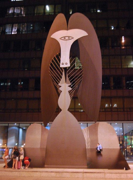
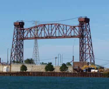

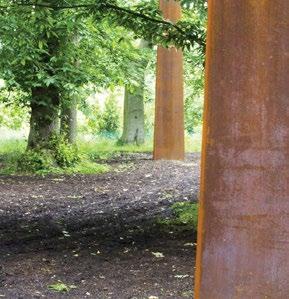
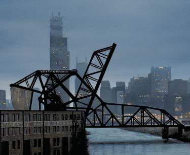
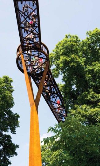
It is currently envisioned that above-ground structural elements would be constructed in weathering (Corten) steel. This material is self finished, i.e. requires no painting during its life, and was used in the highly acclaimed ‘Picasso’ and Daley Center.
After installation and exposure to normal weather the surface of weathering steel develops a rustic finish and texture. Weathering steel resists the corrosive effects of rain, snow, ice, fog, and other meteorological conditions by forming a coating of dark brown oxidation over the metal, which inhibits deeper penetration and negates the need for painting and costly rust prevention maintenance over the years.
Weathering steel has a longer lifespan than bare cold rolled steel. Weathering steel is also better in harsh climates. Harsh climates include environments with exposure to salt and climates where the material will often be wet.
Weathering steel never completely stops rusting. The weathering process occurs after the material is installed. It eventually decreases and from that point on the finish acts as a protective coating for the base metal. This protective coating essentially stops the corrosion. It is important to design and apply special drainage to take any water coming from weathering steel to avoid staining the surrounding areas. There are no adverse effects using it in grass or planted areas.

This section presents a preliminary analysis of the potential navigational, foundation and utility issues that may be encountered during the design and construction of the cableway and landing areas (i.e., the pylons, transfer structures and stations) for the proposed Chicago Skyline cable car system.
The Main Branch of the Chicago River is considered a “bank to bank” channel for federal navigation purposes. It serves the commercial functions of the city and receives large ships and barges as well as tour boats and smaller recreational craft. The navigation for the Chicago River is currently governed by a vertical clearance of 120-feet at the Pennsylvania Railroad vertical lift bridge near Canal Street. The USCG has provided a preliminary determination to reduce the minimum vertical clearance for a fixed type structure over the Main Branch of the Chicago River to 90 feet. However, the variance process to make this change has the potential to be very lengthy and could delay the project from advancing. We will review the 90’ height after meeting with key agencies (ACOE, USCG, e.g.). For the purposes of this report, the clearance for the Skyline was selected to meet the existing 120-foot fixed clearance over the river rather than a 90-foot clearance. This 120-foot minimum clearance would be measured from the lowest point of a cable car pod, including consideration for sag in the cable, over the river.
A full investigation of existing utilities in proximity to the proposed landing areas for the Skyline will be performed during the design phase. A preliminary investigation determined the presence of water, gas, electric, communications and sanitary utilities as well as subway tunnels, utility tunnels and freight tunnels in the project area. The pylons and station foundations should be strategically located to avoid these utilities wherever possible while balancing the mechanical design needs for the cable car system and the structural foundation needs for the stations and pylons. However, it is common that new construction within an urban
area may require relocation or rerouting of existing utilities. The existing condition of utilities is discussed further is Section 3.2.
It is anticipated that the stations will require electric, water, gas, sanitary, and communications utilities to service both the cable car system and the building operations of the stations. In addition to servicing the Skyline Cable Car system, the stations will likely include some combination of the following: restrooms, retail shops, bike storage and rental (through the Divvy bake share program), and a food and beverage program. All of these services will require various utility feeds. Given the proximity of the Skyline to existing buildings and developments, it is anticipated that bringing the utilities to these sites is feasible. Each station will need to be equipped with an independent emergency generator capable of sustaining necessary life safety requirements in the event of a power outage.
The transfer structures will require electrical feeds to service the mechanical operations of the cable car system and to accommodate planned lighting on the pylons. The vertical pylons will potentially require electrical feeds to accommodate planned lighting.
Chicago’s Riverwalk Project previously conducted a geotechnical investigation of the soils within the Riverwalk from State Street to Lake Street. The investigation was based on three soil borings conducted June 2011 as well as fourteen existing borings from the Wacker Drive Reconstruction Project taken from October 1999 to March 2000. In addition, eleven soil borings were conducted for the East Wacker Drive Project from Michigan Avenue to Field Boulevard in March 1973 (see Figure 2-1).
The soils were determined to be river muck from approximately -13 to -23 Chicago City Datum (CCD), soft to medium stiff clay (-24 to -40 CCD), medium stiff to very stiff clay (-40 to -65 CCD), medium dense silty clay loam to silt and very dense silty/sandy loam or clay loam/silt down to bedrock. Bedrock is located at an approximate elevation between -100 CCD and -110 CCD. The current top of pavement elevation at the Riverwalk is approximately 5.0 CCD.
The Chicago Riverwalk Geotechnical Investigation recommended a driven pile deep foundation system for support of the Riverwalk and the underbridge structures. Hard driving of the piles is anticipated to occur below elevation -70 CCD where very dense soil conditions exist. The report also indicated that downdrag will be an issue for deep foundations due to the presence of compressible soils and subsequent excessive settlement. A geotechnical analysis will be performed for the Skyline. A Geotechnical Report will provide foundation recommendations to address the specific design requirements of the system, including soil parameters to use in design that will account for issues like downdrag and excessive settlement. It is anticipated that at least two or three soil borings will be required in Gateway Park to better understand the soils in the vicinity of the Navy Pier Station and the first pylon. It also would be desirable to perform a soil boring in the park east of Lake Shore Drive to assist in the foundation design of the transfer structure. Additional borings may be required along the Riverwalk pending determination of the final route alignment and foundation locations.
The foundation design for the pylons is anticipated to be unique to each pylon in response to the expected loading. A number of pylons will serve as tension pylons, which would impart a net upward tension on the foundations. In addition, all foundations will be required to resist moments from the cable transitions and/or wind loading. The arrangement of the piles will have to accommodate the large moments imparted on the foundation while avoiding existing underground structures and utilities. Consideration of the existing soil conditions indicates that it is likely that the deep foundation piles will be driven down to bedrock.
The foundation design must avoid existing utilities and existing foundation structural elements. A preliminary assessment of potential tension pylons, soil conditions and site constraints revealed that micropiles would be considered an appropriate foundation type. Micropiles can be constructed along the Riverwalk without taking too much of limited area at the Riverwalk level. If driven piles were selected a large drill rig would be required for construction and difficult to locate to perform
the work. Also the relatively smaller pile size of micropiles will aid in placing foundations around existing tunnels and utilities.
The Skyline route crosses the navigation channel of the Chicago River, however the system will not locate any pylons within the waterway at any point along the route nor will the cable cars or pylons encroach on the required vertical or horizontal navigational clearances.
Construction of a project as complex and geographically widespread as the Skyline Chicago Project will require significant coordination and communication in order to be effective. The construction process is made even more challenging due to the fact that all of the work will be constructed within areas that are continually heavily congested with both pedestrian and vehicular traffic. In the summer months, marine traffic mostly consisting of tour boats and pleasure craft will also need to be taken into consideration.
To minimize disruptions to the vehicular, train, and pedestrian traffic, the most effective way to construct this project is to utilize a marine fleet of equipment to satisfy the hoisting and material placement requirements. In order to allow for concurrent work and condense the project schedule as much as reasonably possible, several barge-mounted cranes and accompanying material/access barges will be implemented. This work will need to be closely communicated with the United State Coast Guard in order to ensure compliance with all regulations and special requirements throughout the construction period.
While the balance of the work will be performed from the water, temporary lane closures on both upper and lower Wacker Drive and Columbus Drive will undoubtedly be necessary to accommodate site access and material deliveries. Proper coordination with CDOT, the City of Chicago’s Permit Department, and Office of Emergency Management and Communications (OEMC) will be critical to the success of the project.
Because of the extremely tight and congested work areas that must be dealt with on the project, it will be necessary to procure off-site property to accommodate material and equipment storage. Site security will be necessary at this off-site location to ensure that theft or damage to critical project materials does not occur.
Another major key to the successful execution of this project will be collaboration and coordination with the Chicago Department of Transportation’s (CDOT) group that will be administering the upcoming Riverwalk enhancement projects. As the majority of the Skyline project occupies the same physical space as the Riverwalk projects, issues such as construction details, access requirements, common work items, etc. must be properly communicated between the two contracts to avoid conflicts. The timing of the Riverwalk work will also be critical, since the means and methods employed to construct the Skyline work may change depending on what physical work has already been put into place by the Riverwalk project.
It is anticipated at this time that the total time necessary to complete the Skyline work is approximately twenty-two (22) months. With the proper communication and coordination, all aspects of the construction of this project appear practical and reasonable at this time.
Security will be a key issue during operation of the Chicago Skyline and, because of its importance, needs to be considered early and continuously through the design and construction phases. First and foremost is the need to undertake a strategic approach to planning and forecasting security requirements in order to ensure that Skyline security is (1) aligned with the project’s vision and business objectives; (2) reflects a risk-driven approach to all potential threats and vulnerabilities; (3) carefully integrated across the major drivers of security program excellence for critical infrastructure (e.g., strategy, people, process and technology); (4) supported with rigorous oversight and management discipline; and (5) agile in adapting to constant changes in the risk environment confronting the aerial cable car system.
Key actions, issues and outputs related to security strategy will include, for example:
• Determining the risks, threats and vulnerabilities confronting the Skyline
• Analyzing these findings for their implications for the system’s design, construction and operation
• Developing a Master Security Strategy Blueprint that defines the mission, vision and goals of the program — as well as its organizational chart and structure, strategic program components, areas of domain excellence and specific operational goals that must be achieved by the end of 2013, 2014, 2015 and by spring 2016
• Translating the strategy’s high-level elements in an actionable Operational Security Plan
• Authoring a comprehensive Emergency Management Plan
• Defining the actions, roles and responsibilities required of specific personnel in order to ensure continuity of operations (CONOPS) for a wide range of potential scenarios
Key actions, issues and outputs related to people will include, for example:
• Determining whether Skyline is better served by engaging security personnel using an in-house, outsourced or hybrid service engagement model, including cost/benefit analysis of all three options
• Engaging both hiring and employment strategies to counter the “insider threat;”
• Maintaining high levels of security awareness among all Skyline personnel and vendors as well as members of the general public
• Ensuring high competency levels among the staff with respect to critical security and emergency communications, technologies and equipment
• Planning for rapid access, when necessary, to highly specialized experts in domains such as counter-terrorism, surveillance, and CBRNE (chemical, biological, radiological, nuclear and high-yield explosives) detection
Key actions, issues and outputs related to process will include, for example:
• Authoring security policies, procedures and practices
• Identifying communications protocols and escalation procedures for a wide range of events
• Conducting active liaison with critical third parties, including the execution of mutual memorandums of understanding (MOUs)
• Planning monitoring, surveillance, countersurveillance and electronic security countermeasure (TSCM) sweeps
• Identifying information-sharing and intelligence gathering activities, resources and processes
• Conducting strategic tabletop exercises
Key actions, issues and outputs related to securityrelated technology and equipment will include, for example:
• Developing a comprehensive physical technical security master plan
• Drafting Requests for Proposals
• Developing budgets and rough order of magnitude cost estimates for each area
• Selecting technical and physical security integrators
• Creating checklists, graphics, blueprints and job aids for field and site use
• Facilitating the oversight of selected technical and physical security integrators
• Implementation
The pods would normally travel at approximately 900 feet/minute between stations and 60 feet/ minute in stations for passenger embarking and disembarking. The total design carrying capacity is 3,375 passengers / hour in each direction.
The total length of the cableway is approx 1.6 miles, and it will comprise two separate drive systems. The general public will not be aware of this as during the operation of the cableway the pods will move seamlessly between the two systems at Columbus Station.
The East drive system consists of: the Gateway terminal station at Navy Pier; a bifurcated pylon adjacent to the terminal station; the transfer structure at Lake Shore Drive, four straight pylons; and the east half of the station at Columbus. These locations are connected by one continuous cable.
The West drive system consists of: the west half of Columbus; three transfer structures; six straight pylons; the terminal station at West Wacker; and a trifurcated pylon adjacent to the to the terminal station. These locations are again connected by one continuous cable.
In the westerly travel direction the pods are detached at Columbus from the East cable, moved west along the station by a conveyor system and then re-attached to the cable of the East system to continue their journey. The same applies in reverse as the pods pass through Columbus, travelling east from West Wacker to Navy Pier. This arrangement of two separate drive systems means that there will be two drive motors, one for each system. These are located above platform level in Columbus station.
At the terminal stations, at either end of the system as a whole, the pods are also disengaged and re-engaged on and off the cable, in order to allow passengers to disembark and embark. This is the usual arrangement on high speed cableways because, if the pods were not removed from the cable, then the speed of the cable would be too fast to allow passengers to get on and off. In other words, the cable speed of 9mph (4m/s) required in order to make the overall travel time acceptable is too fast for the load and unloading process. So to be able to keep the pods (and hence the cable) moving at the required speed it becomes necessary to remove the pods from the cable to be able to control them and to allow passenger to get on and off.
At the transfer structures the pods also are detached and then re-attached from the cable as the cable is deflected horizontally around a bull wheel at the change of direction, but here the doors of the pod remain shut and locked and the passengers are not able to embark or disembark from the pod while it moves on the slower speed conveyor.
The cables, to which the pods are attached, are driven by friction at the “drive bull wheel.” The drive bull wheel is rotated by an AC variable frequency electric motor acting directly on the shaft of the wheel. The drive bull wheel is fixed in position and therefore, in order to be able to induce tension into the cable, the opposite ends of the drive system, in this case the two terminal stations, are known as the tension stations. At each tension station the “return bull wheel” is usually mounted on a trolley which can move horizontally. The trolley is moved by a hydraulic ram tensioning system. The tensioning system pulls the trolley (and the return bull wheel) in the opposite direction to the cable and applies a tension force into the cable.
The pods are attached to the cable by a grip which has a pair of moveable jaws that are automatically opened and closed to allow the pods to be engaged on or disengaged from the cable.
A device such as a cableway, like many other systems that are used to move around people or products, is a mixture and a combination of a number of different engineering disciplines and aspects of design. The steel wire cable used as the cable itself is a critical element of the device but wire cable technology is well established and is inherently very reliable in the context of a continuous loop cableway system. It is likely that the cable will require changing at some point in its life, but regular testing and inspection will inform the operator when that is required. The remainder of the device is a combination of mechanical and electrical elements, the major components of which are the drive motors, the bull wheels and the conveyors that will move the pods through and around the stations.
In addition to this there is a control system that will ensure that the device can be operated as designed in a safe and reliable manner. The interface between the control system and the operator is the control panel or desk. This will be located at Columbus station and will allow the operators to both monitor the various functions of the system, but also provides them with the ability to control the pods in the station as the passengers embark and disembark. Secondary operator control panel locations will be provided at the two terminal stations where passengers can also embark and dis-embark.
The maintenance requirements will be set out as part of the design process so that the operator knows in advance what the likely engineering staff requirements are going to be, what consumables and spare parts are likely to be required, and hence what costs will be incurred. A combination of robust design and well-planned maintenance will ensure that the device will operate reliably through its intended life.
The technology associated with this type of machine is well known and well established. There are numerous examples of these machines in the Americas, Europe and Asia. As with all other types of transport systems, there are a number of codes, standards and processes that contribute to safety and these will be applied to this design and installation.
In terms of safety, there are a limited number of hazards associated with cableways and the design process requires that a formal risk assessment is undertaken to ensure that all the hazards are identified. Then from the hazard assessment the risks are either removed or mitigated, firstly by design if possible or secondly by the operating procedures if that is the only option. The design itself (including the proposed operating procedures) will be subject to an independent review and during manufacture the manufacturing processes are inspected to ensure that the various parts are built in accordance with the design. Once built, further inspection and testing is undertaken at intervals planned to ensure that the device functions as designed.
The primary safety provision is to ensure that the cable can drive at all times during the operating cycle, so the design incorporates a simple and very reliable drive system with the facility to provide back-up power by on-site generation if the normal main supply is interrupted. The control system is also designed to give priority to the safe drive of the cable to allow all passengers to be returned to a disembarkation station as soon as possible. If both the main power supply and the back-up power supply fail, or if the motor itself fails to operate, a separate secondary drive system can be brought into use. This secondary drive system bypasses the main drive motor and shaft connection, and engages a “ring and pinion” drive motor directly onto the bull wheel. This drive motor would only be used in an emergency to drive the cable for long enough to return all the pods to stations for disembarkation (the cableway would then cease operations, until such time as the primary drive system was restored).
As a final “last-resort” emergency, if all of the above noted drive methods still fail to move the cable and return the pods to a station, the passengers can be rescued from each stationary pod by a “tried and tested” person rescue system which will lower each passenger to the ground (or to a boat if over water) on an accompanied basis. This will be carried out by a dedicated emergency rescue provider, based in Chicago, who will be on a standby contractual arrangement with the operator. Similar arrangements apply to all major modern passenger-carrying cableway systems.
Ride Operations and Maintenance should fall within the range of $15–17 million per year with operations and yearly expenses in mind. These figures take into account both the lift mechanics and electronics as well as hired staff that maintain and run the systems.


This section presents the preliminary civil design investigation for the proposed Skyline cable car system. Unlike traditional transit modes, like a subway tunnel or elevated train line that require rather large infrastructure investments, a cable car system’s infrastructure is limited to its occasional landing areas which include the supporting pylons and the stations. The site civil conditions at the pylon, transfer structure, and passenger station locations must be evaluated to accommodate the necessary utility requirements, grading adjustments and maintenance of traffic operations. These items are discussed herein.
At the start of the design phase of this project, all existing utility locations within the limits of the Skyline pylons and stations will need to be determined (see Figure 3-1). This design phase activity will require extensive effort as this is in the heart of Chicago, an urbanized area. It is to be expected within urbanized areas that a new construction project will encounter utility conflicts and have to either design around the utilities or move them. Utility relocations in areas similar to this may become a major portion of the overall construction budget if a detailed analysis of existing utilities is not done in the design phase. This is especially true in downtown Chicago where utilities have been installed and re-routed for decades without necessarily good record keeping practices. The limits of the Skyline route crosses over existing water, gas, electrical and communication lines, subway tunnels, utility tunnels and freight tunnels.
The existing utilities will have to be well understood and avoided wherever possible. The vertical pylons are tentatively positioned at approximately the face of the existing river wall from State Street to Franklin Street, therefore the utilities crossing the river will likely be the potential conflicts. Moving utilities in the river would be a costly undertaking. Generally, utility crossings occur at the street or bridge crossings therefore utility conflicts are more likely to occur at those locations. The Franklin Street Transfer Structure, Columbus Drive Station and the West Wacker Station will create the most difficult utility coordination challenges.
As an example of the utilities that will be encountered, the following describes four pylon and one transfer structure locations and the possible utility conflicts:
• Pylon W2
This location is adjacent to the Franklin Street bridge located to the southwest. Near this location are two 8” diameter sewer lines that cross the river and will need to be exactly located during design to avoid conflict.
• Pylon W3
This pylon is located between Wells Street and LaSalle Street. In this area one 12”, two 8” diameter sewer, one water main and one electrical main cross the river and will need detailed survey to avoid conflict.
• Pylon W4
This pylon is located between Clark Street and Dearborn Street. This corridor contains seven 8” sewer river crossings and one electrical main crossing which will need detailed coordination to avoid conflict.
• Pylon W5
This pylon is located between Dearborn Street. and State Street. This block is referred to as Room 1 and contains eight 8” sewer river crossings and one electrical main crossing which need to be avoided in placement of the pylon.
• Transfer structure at Franklin Street
This transfer structure is directly over the Franklin Street bridge which will require foundations for the structure on either side of the bridge. The utilities adjacent to the Franklin Street bridge crossing the river which may be in conflict with the station foundation include two 8” sewer, one 12” sewer, one 24” sewer, one 4” water main, one 8” water main, one electrical line and one gas main. All crossings will need to be avoided in foundation positioning.
These examples will be typical at every foundation location and each pylon, transfer structure and passenger station will need extensive utility investigation. As indicated prior, this utility investigation should be done far in advance of actual system design to allow time in the overall schedule for possible utility relocations.

During schematic design, it will be required that an Information Retrieval request (IR) be submitted to the Chicago Office of Underground Coordination (OUC). The OUC will notify the requestor when the IR has been distributed to all utility companies and when all responses have been received, typically required within 30 days. This information, which is generally just schematic utility maps, is then given to the designer. The designer will determine possible conflict then a series of meetings with utility companies will take place to refine the design to avoid or move the conflicting utility. This process takes an extensive amount of time.
Overall the utility investigation should begin far in advance of the actual system design as the utilities will govern the design location of all the structures associated with the Chicago Skyline.
The construction staging scheme is likely to include construction activity from barges in the Chicago River. Working from a barge would potentially minimize disruptions to roadway traffic, but could affect waterborne traffic on the Chicago River. Given the proximity of the project to adjacent roadways, it is possible that a single lane closure on the upper level of Wacker Drive would also be needed for periods during the construction.
This project will likely require the development of MOT plans to address the disruption or altering of vehicular, pedestrian, and bicycle traffic required for construction. These plans should be developed in accordance with standards from the City of Chicago, the Illinois Department of Transportation, and the Federal Highway Administration’s Manual on Uniform Traffic Control Devices (MUTCD). Coordination with the Chicago Department of Transportation (CDOT) will be necessary and ultimately CDOT will be the approving agency for the MOT plans.
The Navy Pier Station construction could require minimal MOT given the site is located in an open green space area adjacent to vehicular and pedestrian traffic. Construction staging may require an MOT plan for pedestrian re-routing or a lane closure.
The Columbus Drive Station and Franklin Street Transfer Structure will likely require MOT concepts to be developed in order to construct the framing for the structures over the roadway. Temporary closures of Columbus Drive may be required, for example, to erect the steel truss framing,temporary lane closures on Lower Wacker Drive may also be required for utility connections and material delivery. It is anticipated that construction will be strategically scheduled to minimize street closures to low-traffic time periods to include night work. The West Wacker Station will also likely require MOT concepts to be developed given that the terminal will be constructed immediately adjacent to a heavily traveled section of the downtown area. The pylon construction also has potential for lane closures for electrical service connections.
River boat and barge traffic will need to be coordinated on a daily basis and since the construction of the riverwalk will be reducing the width of the river, this coordination will become more intense. Working and material storage barges will likely be placed in the river for the duration of the construction project and will require constant attendance in terms of river traffic coordination.



This section discusses the existing conditions related to landside access where the proposed Skyline stations would touch down at ground level. The impacts the stations would have on access for each transportation mode are considered in Section 5.1.
Gateway Park is a 19-acre open space owned by Navy Pier. The station would be located between the two legs of N. Streeter Drive immediately south of a 35-foot wide east-west sidewalk known as the Gateway Promenade (see Figure 4-1). The station would not impact the existing or proposed fountains in Gateway Park between the Promenade and Grand Avenue.
Traffic at Gateway Park is heaviest on summer weekends. According to traffic counts from May 2011, the peak hour vehicle volume on E. Illinois Street occurred from 2:00 PM to 3:00 PM on Saturday, with 443 vehicles per hour east of Streeter Drive (Traffic Analysis and Design 2011). This peak hour volume corresponds to an average daily traffic volume of approximately 5,000 to 6,000 vehicles. Volumes would likely be higher when Navy Pier visits peak in July and August. Much of the parking for Navy Pier is available in lots to the west on Illinois Street and Grand Avenue. Many pedestrians walk from the parking lots to Navy Pier. The same traffic counts from May 2011 found 569 pedestrians and bicycles traveling east and west at the Illinois Street & Streeter Drive intersection, so pedestrians and bicycles outnumber automobiles in this area during peak periods. There is also a CTA bus terminal along Streeter Drive north of Grand Avenue.
The Gateway Park Terminal Station at Navy Pier, bounded by E. Grand Avenue to the north and N. Streeter Drive and the Lakefront Trail to the south, would be accessed via a primary entrance at the north end of the station. In addition to this main
entrance, secondary access would be provided for embarking and disembarking riders at the eastern and western sides of the station, respectively. These access points would be at the existing elevation of Gateway Park with slight modifications. The station would also serve as a welcome area and information center for the whole area. Pedestrian pathways and landscaping around the station serve as navigational aids that support the function of these key points of entry/exit (see Figure 4-1).
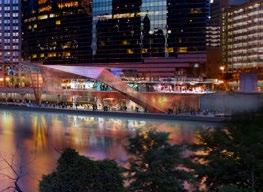
The ground level amenities at Navy Pier Terminal Station would include bike rental and bike storage (in support of Chicago’s new Divvy Bike share program), a grab-and-go food and beverage concession space with limited seating and a small kitchen, restrooms, ticketing, storage and a main hall that provides access to vertical circulation leading to the platform level. This circulation shall include an elevator, stairs, and escalators, and take redundancy measures into account in the event of maintenance or repair. A portion of the roof at this location shall be glazed to allow for the infiltration of natural light into the main hall.
The ground level would be partially enclosed north of the main hall, with floor to ceiling insulated glazing at the food and beverage space, information, café and bike rental/service areas. The ticketing area shall also be enclosed against the elements. The remaining exterior wall portions at the ground elevation would combine the aforementioned glazing with an insulated metal panel wall in the tone of Corten steel. Roof overhangs would form integrated canopies along the perimeter.
The station platform level would be approximately 13’ above grade, with an embarking platform to the west and a disembarking platform to the east. A control room would be located in the middle of the platform at its northernmost end.
Since the platform area would remain essentially open to the elements, particularly to the south where the pods arrive and depart the station, the glazing at this level shall be laminated-toughened single glazing approximately eight feet above finish floor. A perforated, panelized, flat, Corten steel screen wall would enclose the platform and mechanical catwalk levels, giving shape to the


building’s diamond-like, crystalline form. A minimal, painted system of structural steel “ribs” shall support this very light, visually porous screen wall. Integrated LED lighting, infrared heating, and fans would be provided to assist with passenger and operator comfort.
As discussed in Section 1.3.4, the station would be constructed north of the intersection of Columbus Drive & Wacker Drive, both of which are three-level roadways. The main Columbus Drive station entrances would be located on the north side of Wacker Drive at the upper level, with additional elevator and stair access at Columbus Drive Bridge level, and at the Riverwalk level. There are five major hotels with over 5,300 rooms in the vicinity of the station. The Hyatt Regency and the Swissotel have their primary pedestrian entrances on Upper Wacker Drive, the Fairmont and the Radisson have their primary pedestrian entrances on Upper Columbus Drive, and the Sheraton is located north of the Chicago River on Columbus Drive. In addition to the hotels, there are many office and residential buildings in the station area (see Figure 5-14b pp. 86-87).
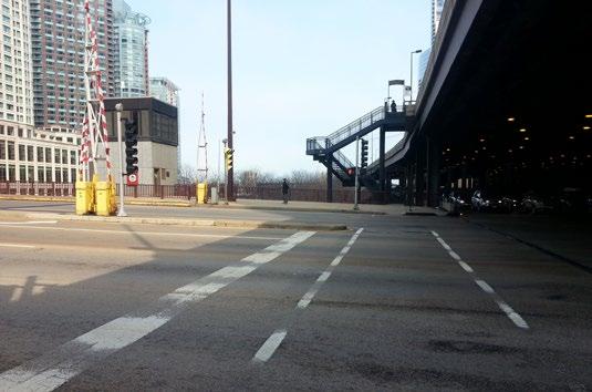
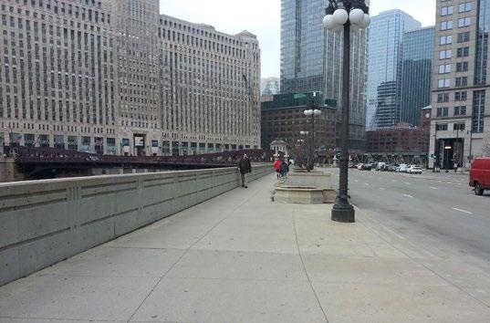
The upper level of Wacker Drive is a five-lane roadway carrying approximately 15,500 vehicles per day (Illinois Department of Transportation 2010). The sidewalk along the north side of the street, which would be adjacent to the proposed Skyline station, varies between 7’-9” to 9’-0” wide, but light poles and traffic signals reduce the effective sidewalk throughway width to 5’-6” at its narrowest point. There is also a bus stop on the sidewalk serving nearly 1,300 bus passengers per day (Chicago Transit Authority 2011). A stairway connects the upper level of Wacker Drive to the intermediate level of Columbus Drive and the Riverwalk. No ramps or elevators are available for pedestrian access. Roadway ramps connecting the upper level of Wacker Drive to the intermediate level of Wacker Drive are located immediately east of the intersection and a ramp from the lower level up to the intermediate level is located immediately west of the intersection.
The upper level of Wacker Drive terminates approximately one block east of the Columbus Drive intersection with a circular turnaround. The upper level of Columbus Drive is a five-lane roadway carrying approximately 7,200 vehicles per day (Walker Parking Consultants 2006). It connects upper Randolph Street to upper Wacker Drive over a distance of 0.25 miles. The intermediate level of Wacker Drive carries approximately 18,400 to 19,500 vehicles per day at this location (Walker Parking Consultants 2006) and provides a fast route through downtown Chicago connecting Lake Shore Drive to I-290, as well as access to loading docks for trucks. There are no sidewalks along the intermediate level of Wacker Drive.
The intermediate level of Columbus Drive is a seven-lane arterial roadway carrying approximately 21,500 to 23,000 vehicles per day (Walker Parking Consultants 2006). The intermediate level of Columbus Drive is busier than the upper level of Columbus Drive because the roadway continues north of Wacker Drive and the Chicago River into the Streeterville neighborhood, and south of Randolph Street through Grant Park to Lake Shore Drive. The sidewalks on the Columbus Drive Bridge over the Chicago River are 10 feet wide. Approximately 1,000 square feet of additional pedestrian space is available on the northwest corners of the Columbus Drive and Wacker Drive intersection; and 1,400 square feet of additional pedestriamn space is available on the northeast corner of the intersection. The stairway on the northeast corner of the intersection is shown in Figure 4-5.
The lower levels of Columbus Drive and Wacker Drive primarily provide access to parking garages for buildings in the area and the City of Chicago Central Auto Pound lot at 500 E. Wacker Drive. The McCormick Place busway, a 2.5 mile long bus-only roadway connecting the hotels near the proposed Columbus Drive station to the McCormick Place Convention Center, is also accessed from the lower levels of the roadway network. The Riverwalk is separated from the lower level intersection of Columbus Drive and Wacker Drive by a fence with visual screening. There is pedestrian access to the Riverwalk available near the intersection of the lower level of Wacker Drive and Field Blvd to the east.


The Riverwalk at this location is a 10-foot wide multi-use path, with the path curving north under the Columbus Drive Bridge. The areas where the Skyline station would be constructed on either side of Columbus Drive immediately north of Wacker Drive are currently used as open space, leaving adequate room for the proposed Skyline station.
The main access to Columbus Station would be at Upper Wacker Drive, which is approximately 48 feet (14.7 m) above the Riverwalk. Stairs and elevators would connect the Columbus Drive bridge level and the Riverwalk level to the upper Wacker Drive level (see Figure 4-3). At the upper Wacker Drive level there would be a ticket office, a grab-and-go food and beverage concession space and a modestly sized ownership-operated retail outlet selling souvenirs, guidebooks, small-scale gifts, confectionary, and other items. Public restrooms will be provided adjoining the retail outlet and food and beverage concession outlet.
The station platforms would be approximately 50 feet (15 m) above upper Wacker Drive, a similar height to that of the Chicago Picasso and Calder Flamingo. The eastbound travel platform would be located on the south side of the station and the westbound travel platform would be located on the north side of the station. The operator’s office or control booth would be located in the middle of the westbound platform. Each platform would be divided into boarding and alighting areas.
Each of the two platforms would be served by two 20-person capacity elevators, operating on a one-way system. All elevators alight at upper Wacker Drive level. Two elevators would serve the Columbus Drive bridge level and the Riverwalk level, one in the southwest corner and the other in the northeast corner. Emergency stairs shall provided for each platform.
The station platforms would be open on their east and west sides where the pods arrive and depart, and would be glazed on the north and south sides. The glazing would be floor to ceiling laminatedtoughened single glazing. LED lighting, infrared heating, and fans would be provided to assist with passenger and operator comfort.
Columbus Station would house the two direct drive motors, one for the east cable bullwheel, and one for the west cable bullwheel. Direct drive motors are electric motors with no gear reducer which greatly reduces the noise level. Catwalks shall be provided to access and maintain the drive motors and to access and maintain the conveyor system.
A separate garage structure would be used to house and protect the pods when not in operation or during periods of high winds (see Table 4-7). A conveyor system would be used to transport the pods from Columbus Drive Station down to the garage structure. The structure would be designed to protect the pods from the weather but is not required to be weathertight. Lighting would be provided but not heating. There would be a maintenance area and a wash bay, each large enough to accommodate two pods. The maintenance and wash bays would have infrared heaters and lighting. Catwalks will be provided to access the conveyor system.
Notes:
1. Wind data from the real-time National Oceanic and Atmosphere Administration meteorological station at Harrison-Dever Crib, located approximately 4.5-km offshore from Navy Pier (41°54´59” N, 87°34´20” W);
2. The anemomenter is located 25.9-m above the site elevation of 176.0-m (above sea mean level);
3. Available data (2000 to 2012) includes, for each 5-min interval, the air temperature, the mean and the max. (1-sec gust) wind speed and the wind direction. The 1-sec gust is the max. of all of the gusts during the 5-min interval.

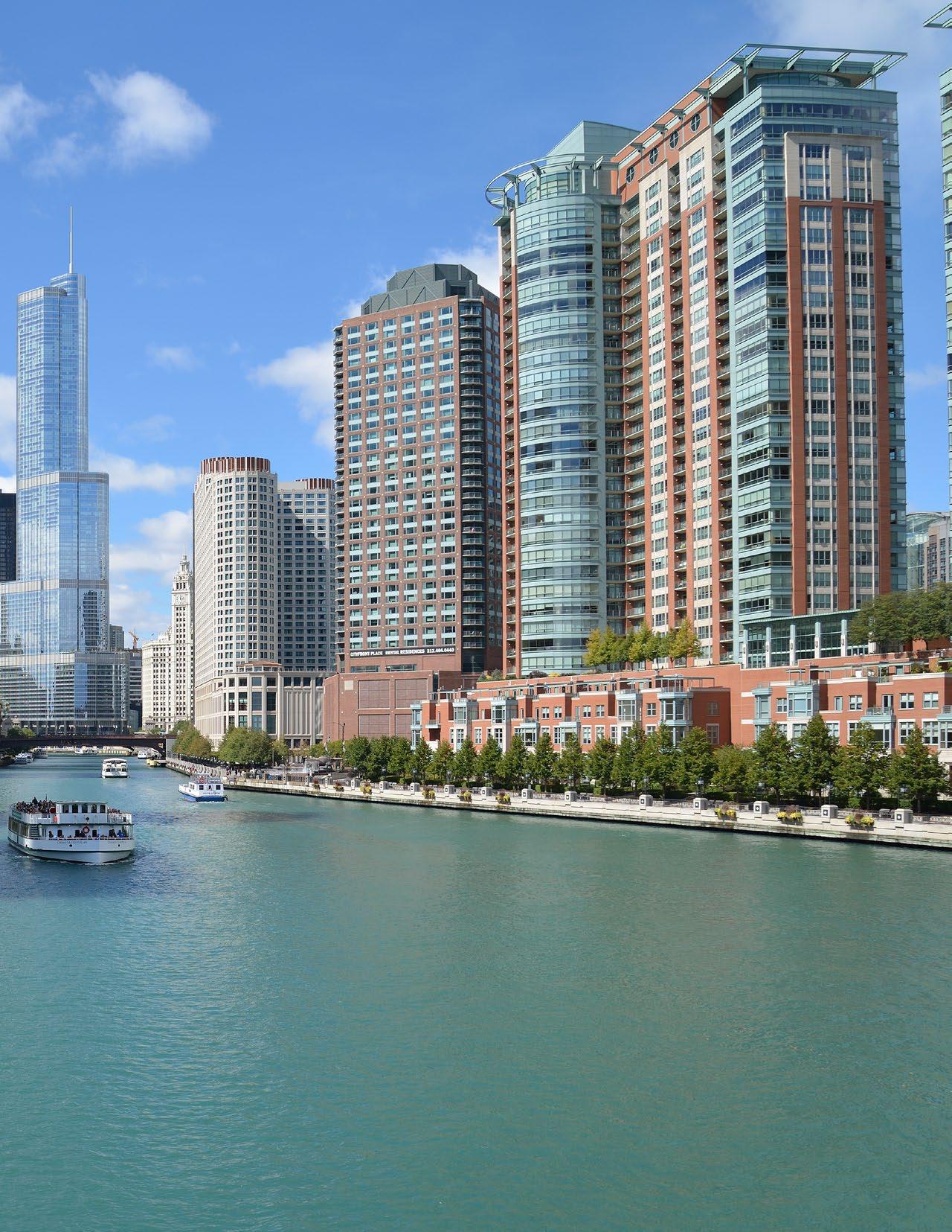
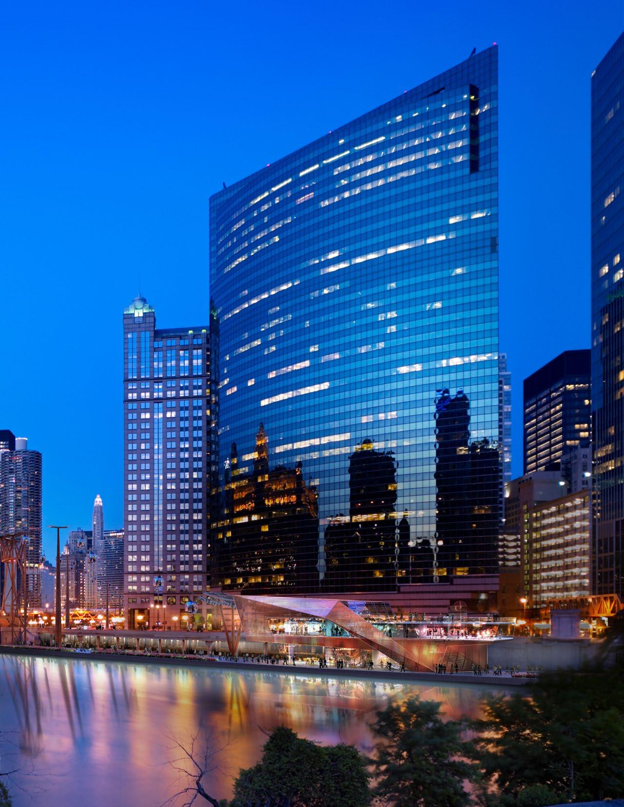
The proposed West Wacker Terminal Station location is currently an office district rather than a tourist destination. It would be less than half a mile from the Madison Street entrances to Ogilvie Transportation Center and Union Station and immediately across the river from the Chicago Sun Times and Merchandise Mart buildings. Across West Wacker Drive just to the south of the proposed station location, 333 West Wacker graces the corner as the Chicago River bends south. The proposed station location is approximately 50’ northeast of the existing bridge house at West Lake Street.
Wacker Drive is a seven lane arterial roadway carrying approximately 23,800 vehicles per day (Illinois Department of Transportation 2010).
Although the overall sidewalk width along the north side of West Wacker Drive between West Lake and North Franklin streets varies from approximately 20’ to 30’, existing planters, streetlights, and street furniture reduce the effective width to approximately 7’-6” at some locations (see Figure 4-9) .
As previously mentioned, this block is part of the Riverwalk extension project. The new river wall between West Lake and North Franklin Streets shall be constructed 50’ into the river from the face of the existing river wall at the Lower Wacker Drive level. The exact demarcation of the proposed station design and its exterior public spaces have not been fully designed (or integrated) into this proposed Riverwalk design by others at the time of this study. The proposed West Wacker Terminal Station shall be accessed from both West Wacker Drive and Riverwalk levels.
The West Wacker Station’s primary entrance at West Wacker Drive, approximately 19’-6” above Riverwalk level, would provide direct access to ticketing, station circulation, and the eastbound travel platform. An operator’s office and restrooms would flank station circulation upon entry and a secure pass-through to a north-facing lobby provides rider access to the station’s retail component directly from the platforms. The platform would be divided into boarding and alighting areas (see Figure 4-8).
Secondary access to the street level retail shall also be provided at the southwestern face of the station on West Wacker Drive. The West Wacker Terminal Station’s retail component shall contain vertical circulation that will efficiently displace users from street level to the partially enclosed bar/terrace at the level above, as well as the lobby and food and beverage at the Riverwalk level below. This vertical circulation shall include an ADA lift and grand stair.
The Riverwalk level program includes a lobby, restrooms, and indoor and outdoor food and beverage. A small kitchen at the southern edge of the station shall support the food and beverage which is serviced by loading access from lower Wacker Drive. The full extent of outdoor program has not been ascertained at the time of this study though the potential for this is suggested in the station design and the prospect of such an experience is highly recommended. Multiple points of entry at the Riverwalk level shall be coordinated with exterior program accordingly and provide direct access to vertical circulation.
Above street level, the West Wacker Terminal Station shall have a partially enclosed outdoor bar/ terrace that is an extension of both the Riverwalk level food and beverage and the street level retail. In addition to this rooftop program, the station shall have a catwalk level, similar to Navy Pier Terminal and Columbus Drive stations, which would allow service access to the conveyor system that facilitates gondola operation at the platform/ street level below.

Very similar to the Navy Pier Terminal Station at Gateway Park, the West Wacker Terminal station shall maintain an essentially open exterior wall condition at the platform area and potentially insulated conditions at areas where program is more concentrated, such as the retail and food and beverage areas. Like the Navy Pier Terminal Station, the exterior “skin” of the building will be formed by a perforated, panelized, flat, corten steel screen wall, supporting painted steel ribs, and a combination of insulated glazing and laminated-toughened single glazing. The architectural expression of this station recalls the crystalline form of the Navy Pier Station in a way that adapts to the complex conditions of both West Wacker Drive and the Riverwalk. Integrated LED lighting, infrared heating, and fans will be provided to assist with passenger and operator comfort.
The square foot area calculations listed in this spread have been generated from the the pre‐schematic design drawing package, submitted under separate cover. These calculations represent areas currently being carried in the design drawings. Some figures are approximate, pending further design study and/or technical data.
All enclosed spaces, restrooms and ticketing booths will be heated, ventilated and air conditioned as required. Areas intended for Retail program shall remain unfinished and without M/E/P/FP systems. Heating and air conditioning will be provided to all indoor spaces where customer and worker comfort is important. Dining, food service and areas where customers will be waiting before going to a platform will have complete HVAC systems. It is anticipated that individual spaces such as retail or restaurant areas will be served by separate dedicated HVAC systems in order to match system control and operation to the operating times of these functional spaces.
1
1
2
1
2
3

This section provides a high-level review of the potential environmental conditions related to construction and operation of the proposed project. This environmental review reflects the environmental resource topics and analysis methodology consistent with the regulatory requirements of the National Environmental Policy Act (NEPA). The essential purpose of NEPA is to make certain that environmental factors are included in the federal government agency decision-making process. This section includes a description and a timeline of the required environmental review and permitting processes.
Existing Pedestrian Volume on Sidewalk 10-hour estimate Peak hour estimate2
Peak-Hour Pedestrian Volume due to Skyline1 Combined Peak-Hour Pedestrian Volume Boardings Alightings
* Estimated based on bus passenger volume and pedestrian volumes on other bridges 1 Assumed half at Riverwalk level and half at street level(s). Street level volumes distributed to appropriate sidewalks based on access locations.
2 Typically estimated to be 12% of 10-hour counts except where actual count data are available. Riverwalk volumes are estimated to be double that of street level to account for increased use in the future.
* Riverwalk plans for the Boardwak show a walkway width of 8 ft. immediately west of Franklin Street
3 Reduces full sidewalk width based on space occupied by street furniture and shy distances for vertical barriers.


The majority of new trips generated by the proposed Skyline would be made by people who arrive in downtown Chicago by transit (bus and rail) or car, and then walk to the stations. The main transportation concerns are therefore related to congestion on sidewalks due to increased numbers of pedestrians or due to queues of pedestrians waiting for the Skyline. These pedestrian impacts, as well as impacts to other transportation modes, are evaluated below.
The Skyline would attract an increased number of pedestrians to sidewalks near stations, along the Chicago Riverwalk, and in Gateway Park west of Navy Pier. The stations would connect to existing sidewalks, but would not reduce their widths. A preliminary pedestrian flow analysis was completed to determine if sidewalk congestion could result from increased pedestrian volumes generated by the proposed Skyline project.
Peak hourly passenger volumes were forecasted as part of the Chicago Skyline Project Report. These volumes were distributed among different walking paths to determine the peak hour pedestrian volumes on sidewalks near the proposed stations. Pedestrian counts were not available along the Riverwalk, but were estimated based on nearby volumes or volumes in similar areas.
Table 5-1 (opposite) combines the forecasted peak hourly passenger volumes generated by the Skyline with the existing peak hour volumes on nearby sidewalks. These estimated pedestrian volumes are conservative, as they assume that the existing peak hour for pedestrian traffic would overlap with the peak hour of demand for the Skyline, and that pedestrians using the Skyline would not already be in downtown Chicago walking along the same route.
Table 5-2 calculates the pedestrians per minute per foot of effective sidewalk width for existing conditions and post-Skyline. These numbers can be
compared to guidelines in the Highway Capacity Manual 2010, which state that the maximum capacity of sidewalks with platoon flow characteristics (common in central business districts) is approximately 18 pedestrians per minute per foot of useable walkway width. The location with the most pedestrians per minute per foot of sidewalk is expected to be on the north side of Wacker Drive between Lake Street and Franklin Street. The existing pedestrian flow rate is projected to increase from 2.1 to 4.4 pedestrians per minute per foot of sidewalk. This flow rate is almost 25% of the potential maximum capacity. The capacities of the sidewalks near the stations are shown graphically in Figure 5-3 and Figure 5-4.
In summary, the estimated sidewalk capacity in the project vicinity would not be exceeded with the addition of pedestrian traffic generated by the Skyline. No adverse impacts to pedestrian flow are expected.
In addition to the pedestrian flow analysis along sidewalks, it is important to design the Skyline to avoid excessive pedestrian queuing on sidewalks. Queues have the potential to develop at locations where the rate of pedestrian arrivals exceeds the rate at which pedestrians can be processed through the queue (i.e., the departure flow rate). This situation could theoretically occur at the point of boarding on station platforms, or as part of the vertical circulation system (elevators and stairways). These issues are evaluated at a conceptual level below, but more detailed pedestrian modeling is recommended at a later phase of the project to identify potential points of congestion and mitigation for queues.
The throughput capacity of the entire system is expected to be just under 3,400 passengers per hour according to the Chicago Skyline Project Report. This is based on pods with the capacity to hold 12 people each arriving at a station platform every 14.5 seconds, and a system loading efficiency factor of 80 percent to account for groups wishing to travel together. The available capacity at each station varies somewhat depending on how many seats are occupied by people who boarded at upstream stations and
have not yet alighted. The peak hourly boardings and alightings in each month are shown in Table 5-5 and Table 5-6, respectively. The highest demand months are projected to be December, July, and August, in that order. Table 5-7 lists the constrained capacity at each station based on the number of upstream passenger boardings and alightings. In all cases, the available seating capacity exceeds the number of peak hour passenger boardings. Therefore, no significant passenger queues are expected to be generated on boarding platforms.
At the West Wacker station, passengers have level access from upper Wacker Drive. A ramp would be provided for pedestrian access to the Riverwalk level. At the Navy Pier station, where the change in level is only one story, stairways supplemented by escalators and elevators will be the primary mode of transportation between the different station levels. At the Columbus Drive station, passengers will be more reliant on elevators to access station platforms from the street level(s) and the Riverwalk level. These elevators present a capacity constraint that could generate pedestrian queues on sidewalks, along the Riverwalk, or at station platforms. To avoid excessive pedestrian queuing, elevators should be designed to accommodate the average number of passengers per elevator round trip or the typical group size, whichever is larger. The maximum number of elevator round trips per hour is calculated based on the elevator speed, the distance to travel, the time required to open and close doors, and time for passengers to board or exit. The following assumptions were taken from the Chicago Skyline Project Report.
Advanced door opening = 1.0 sec
Door opening = 3.0 sec
Passenger boarding time (1-6) = 2.0 sec
Passenger boarding time (7+) = 1.0 sec
Door closing time = 2.5 sec
Start delay time = 0.5 sec
Vertical speed = 4.3 ft/sec
Table 5-8 calculates the average number of passengers per elevator round trip at the Columbus station by dividing the total peak hour passengers by the number of elevator round trips per hour. The average number of Skyline passengers per elevator trip would be expected to be approximately 13 to 14 passengers going to the westbound platform, 3 to 4 passengers going to the eastbound platforms, 3 passengers leaving the westbound platforms, and 16 passengers leaving the eastbound platforms. Preliminary plans for the Skyline include two 20-passenger elevators for each station. This would be sufficient to hold the calculated average passenger volumes shown in Table 5-6, so significant queuing is not expected at the elevators.
For design purposes, elevators should be positioned and sized based upon the desired alighting capacity. A centralized elevator system that can accommodate up to 68 people is desirable. A 60-person queue is based upon the maximum load of five pods of 12 people arriving per elevator round trip. Stairwells should also be available to keep the system flow optimized.
The Skyline is primarily intended to be a tourist attraction, but has the potential to serve as a transit mode if discounted tickets were made available to commuters. The authors of the Chicago Skyline Project Report forecast that the Skyline could attract between 450 and 800 average weekday commuter passenger trips, primarily between the West Wacker and Columbus Drive stations. These commuters would be split between people who live and work in the downtown area, people connecting with Metra trains, and people connecting with CTA trains.
Given the right pricing structure, the Skyline could compete for many of the same commuters who currently connect from Metra and CTA trains to CTA buses, taxis, or water taxis. The Chicago Skyline Project Report forecasts that the system could initially attract approximately 5% of this travel market, with this percentage decreasing to 1 to 3% over time. The demand for the Skyline would also peak in the winter, when inclement weather reduces the desire of people to walk long distances and water taxis do not operate.





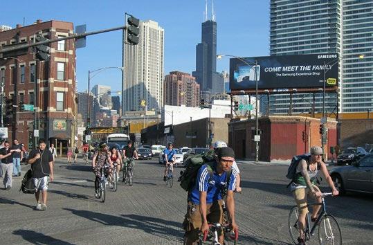
Given the relatively small market share of commuters expected to use the Skyline and the peak demand period in the winter, the overall impact on ridership for other transit modes would be minimal. Furthermore, passenger losses for other modes due to competition from the Skyline could potentially be fully or partially offset by the additional travel demand generated by the Skyline.
The Skyline would not affect any designated on-street bicycle routes. Although designed as a pedestrian path, the Riverwalk is also used by bicyclists. It has been observed that the path’s usefulness as a bicycle corridor deteriorates during periods of peak pedestrian use. Space conflicts between pedestrians and bicyclists would not be reduced nor increased with the Skyline project. Furthermore, bicycles are encouraged to use on-street bicycle routes rather than the Riverwalk.
The addition of the Skyline as a tourist attraction in downtown Chicago would be likely to attract additional automobile trips to the downtown area, especially to Navy Pier, which is less accessible to public transit than the other station areas. The author of the Chicago Skyline Project Report stated that of the projected 3.2 million trips on the Skyline, approximately 1.4 million (44%) could be incremental trips, or trips that would not have otherwise been taken. Approximately half of all trips to Navy Pier are currently made by car. If these percentages are applied to the maximum peak hour boardings of 1,314 passengers per hour at Navy Pier, it is possible that up to 290 additional person-trips could be made per hour to Navy Pier. If there are two to four people per vehicle, there would be 70 to 150 new automobile trips to Navy Pier in the peak hour.
A preliminary traffic analysis was completed for the intersection of Illinois Street & Streeter Drive, the primary automobile access route to Navy Pier. Based on peak hour traffic counts (Traffic Analysis and Design 2011) and analysis using Synchro traffic software, the existing Level of Service (LOS) is estimated to be “B,” which indicates delays of 10 to 20 seconds per vehicle at the signalized intersection. Adding in the additional projected automobile trips would not change the LOS at the intersection. Traffic impacts at other intersections have not been evaluated, but the new trips would be dispersed among more routes with increased distance from Navy Pier, reducing the number of new trips to be assigned to any particular intersection or traffic movement.
Parking for these vehicle trips would be expected to be accommodated by the existing 1,600 parking spaces in the West and East Garages at Navy Pier. Additional capacity is available in the surface lots one block west of Navy Pier and garages throughout the Streeterville area. No new parking facilities are planned as part of this project.
In addition to the private automobile trips, there could be an increased need for on-street loading zone areas near stations for taxi and bus passengers. For example, a loading zone for private buses is being considered along the north side of upper Wacker Drive near the Columbus Drive station, but additional traffic analysis is required to determine the feasibility of this option. On-street loading zones will be coordinated with the Chicago Department of Transportation and the Illinois Department of Transportation depending on roadway jurisdiction. No additional off-street loading zone improvements are anticipated at this time.
The project will be constructed in accordance with all applicable ADA standards. The addition of elevators at stations and an ADA-accessible ramp at the West Wacker terminal will likely improve access to and from the Riverwalk.

The proposed Skyline project would be located in the City of Chicago Central Business District (CBD), which contains a high density mix of residential and commercial uses. The project would include one station near Navy Pier in the Near North Side Community Area and two stations along the south side of the Chicago River in the Loop Community Area. Data from the Chicago Metropolitan Agency for Planning (CMAP) and the US Census has been used for demographic analysis. Figure 5-12 shows the US Census tracts defined as the “study area.”
Population and employment trends for the study area are shown in Table 5-9 and Table 5-10, respectively, and compared to the same data for the Near North Side, the Loop, the City of Chicago, and Cook County. Data from CMAP show that the population of the study area increased by 54.7% between 2000 and 2010, even as the population of the City of Chicago declined by 12.8%. Population is expected to continue to grow in the study area from 2010 to 2020, but at a slower rate. Employment in the study area, the City of Chicago, and Cook County all decreased from 2000 to 2010, but employment growth in the study area is expected to outperform the city and region as a whole between 2010 and 2020.
The project would not be anticipated to displace residents or businesses. The project would pass by five hotels, two condominium buildings, and one apartment building along the south side of the Chicago River, but the closest hotels would be approximately 95 feet from the Skyline alignment and the closest residential building is 140 feet from the alignment. There would be no barriers constructed that could divide neighborhoods. The project could improve community cohesion by introducing a new transportation connection over the Chicago River between the Near North Side and Loop Community Areas.
Executive Order 12898 “Federal Actions to Address Environmental Justice in Minority Populations and Low-Income Populations” requires the identification of low-income and/or minority groups (approximate number and location) within a community who may be affected by a proposed project and the assessment of disproportionately high and adverse impacts. Similarly, Title VI of the 1964 Civil Rights Act, states that Federal agencies are required to make certain that no person is excluded from participation, or denied the benefit of, or subjected to discrimination based on race, color, national origin, age, sex, disability or religion. Projects located within minority, elderly, disabled, and/or low-income communities may require intensified public involvement activities to garner local participation.
The racial and ethnic composition and the mean household income of the study area are summarized in Table 5-11. The results show that the population in the study area is predominately Caucasian. There are no other known groups of religious minorities, elderly people, or disabled people that could be affected by the proposed project.
As indicated in Table 5-13, the average income in the study area is 1.8 and 2.0 times higher than for Cook County or the City of Chicago as a whole, respectively, and 6.3 times higher than the poverty guidelines for a family of four from the Department of Health and Human Services (HHS).
Source: US Census, HHS


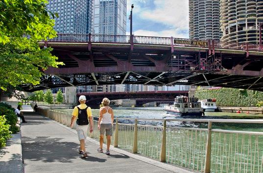
 Figure 5-13
The locations of public and community facilities such as fire stations, hospitals, religious facilities, and schools, are shown in Figure 5-13. The nearest police stations and libraries were also considered, but are located just outside of the area shown on the map. There would be no displacements of nor access restrictions to public facilities associated with the project. Facilities within two blocks of the proposed Skyline include Navy Pier, the Engine 13 fire station at 259 N. Columbus Drive, and the Seventeenth Church of Christ Scientist at 55 E. Wacker Drive. Navy Pier would expect additional visitors as a result of the Skyline project. MOT plans for construction would require coordination with local emergency service providers to maintain adequate service.
The project would introduce a new travel option along the main stem of the Chicago River, and across the river to Navy Pier. The conversion of an underutilized travel lane into a pedestrian plaza is being considered on the north side of Wacker Drive near the proposed Columbus Drive station to provide additional sidewalk space near the station area. There are currently no other planned permanent road, sidewalk, or path closures.
There would be temporary closures of Columbus Drive immediately north of Wacker Drive in order to construct of the project. Travel lanes on other bridges or Wacker Drive may also need to be temporarily closed for construction purposes. Detour routes for all travel modes would need to be planned in coordination with Chicago Department of Transportation, the Office of Emergency Management and Communications, and the Chicago Fire Department. Routes would be signed in accordance with the standards outlined in the MUTCD.
The Skyline is expected to be a major new tourist attraction for downtown Chicago, potentially attracting 3.3 million passengers in the opening year of 2016 according to the Chicago Skyline Project Report. These visitors would be expected to
spend nearly $75 million on the Skyline alone, resulting in a direct economic impact of approximately $9 million in annual sales tax revenues, with various portions going to the State of Illinois, Cook County, and the City of Chicago, primarily from the 9.0% amusement tax on admissions revenues which generates approximately $5.5M per year. As an indirect impact, the Skyline would generate additional tax revenue due to increased attendance and spending at downtown hotels, restaurants, museums, and other facilities.
As previously shown in Table 5-9 and Table 5-10, additional jobs and residences are expected in the study area independent of the proposed project. According to the Chicago Skyline Project Report, the project would create approximately 400 construction jobs and, when operating, an estimated 329 new full-time equivalent jobs when including staff and management, and would indirectly generate other jobs in the hospitality and service industries due to the increased number of visitors.
The study area is a high density central business district, developed largely with high rise office and residential structures. In addition to being the primary job center for the region, Downtown Chicago is a major tourist destination due to its numerous museums, restaurants, parks, and destinations such as Navy Pier. The proposed Skyline project would be integrated into the design of the Riverwalk from approximately Lake Street to Lake Shore Drive, where it would cross the river to reach Navy Pier. The project would be consistent with the vision of the Chicago Riverwalk Main Branch Framework Plan “to establish a unique pedestrian waterfront environment along the south bank of the Chicago River.” Permanent easements would be required to construct stations, support pylons, and a storage facility for out-ofservice pods. Aerial easements would also be desirable for the route.
The impacts to pedestrian and bicycle facilities are discussed in Section 5.1.1. The project’s stations would connect to sidewalks along Wacker Drive, Columbus Drive, and the Chicago
(above)
(below)
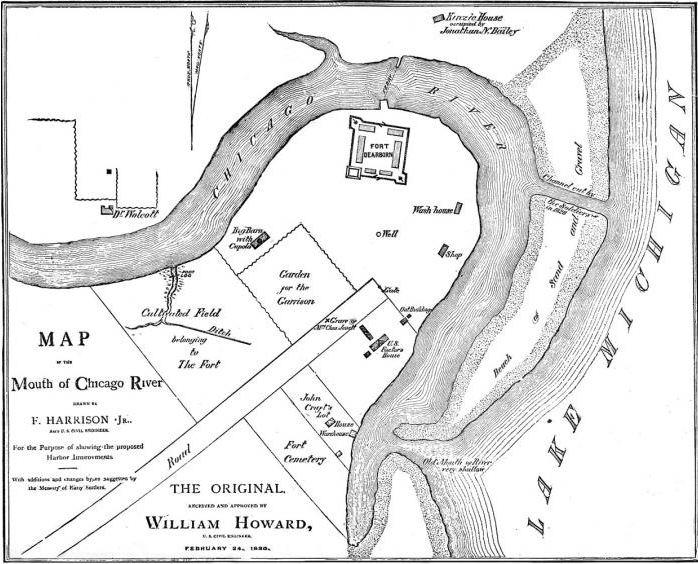
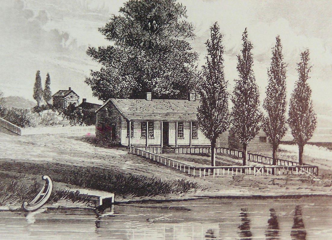
Riverwalk. The number of pedestrians would be expected to increase near the proposed station entrances, and along Wacker Drive and the Riverwalk between stations. Designated bicycle facilities would not be impacted by the proposed project. The Riverwalk is primarily a pedestrian facility, but it is sometimes used by bicyclists as a way of linking to the Lakefront Trail. The volume of pedestrians during certain hours can already lead to slow movement for bicyclists, particularly west of Columbus Drive. Increasing the numbers of pedestrians on the path would not be expected to markedly change the existing operating conditions for bicyclists.
Chicago is world-renowned for its varied high quality and historic architecture. The corridor selected for the Skyline focuses on classic examples of this architecture which is a primary driver for attracting many tourists to the city. The Skyline will offer an exciting new and unique way to experience Chicago’s historical architecture while continuing to demonstrate that Chicago, the epitome of the modern city, is taking another step forward into the future.
While the Skyline is a positive addition which enables visitors to experience the rich cultural heritage of the city, serious consideration will be given to significant historic sites, including buildings, objects, districts, bridges, archaeological sites, and those eligible for the National Register of Historic Places (NRHP) during project development to comply with Section 106 of the National Historic Preservation Act (NHPA).
Consultation would be required related to City of Chicago Landmark sites, including the series of historic bridges spanning the Chicago River, as well other potentially historic properties and cultural resources that may be physically or visually impacted along the Skyline’s route. Information would be gathered about buildings, structures, sites, and other cultural resources currently listed as City of Chicago Landmarks, or identified on the City’s Historic Survey as a “Red” or “Orange” rated site. This identification includes sites currently listed on the National Register of Historic Places, either individually or as part of historic
district. In compliance with 36 CFR 800.4, Identification of Historic Properties, the project’s area of potential effect (APE) would need to be established in consultation with the Illinois State Historic Preservation Officer (SHPO).
The Chicago River was an important Native American settlement site long before the Europeans began to arrive in the area. Tribes such as the Illinois and Miami were encountered by early French traders during the mid- 17th century. The name “Chicago” is believed to have derived from “Chicagoua” a Native American name for the wild garlic plants that grew along the river banks. The Native Americans were also the ones who showed early French explorer Louis Jolliet and missionary Jacques Marquette the portage linking the Chicago River, and thereby the Great Lakes, with the Des Plaines River which led to the Mississippi River.
Although Native Americans were settled in the area, French fur traders began to move in by the late 17th century and established La Mission de l’Ange Gardien in an area believed to be where the Merchandise Mart now stands. Their settlement did not last long however, for hostilities with the surrounding Native Americans drove them out. No further non-Native American settlement occurred until the late 18th century when the Haitian-born Jean Baptiste Point DuSable built a permanent home near the mouth of the Chicago River. A plaque in Pioneer Court, north of the river on Michigan Avenue now, designates DuSable’s home site as a National Historic Landmark.
Hostilities between Native Americans and American frontiersmen continued during the latter part of the 18th century and culminated in the Northwest Indian War. By 1795 the war was over with the U.S. gaining additional territory in the region. The Treaty of Greenville was signed between the U.S. and a coalition of Native Americans which ceded much of area in the Northwest region, which at the time consisted mainly of Ohio, Michigan and Detroit, to the US. Part of this territory included the area around the mouth of the Chicago River. The U.S government established their presence on the newly ceded
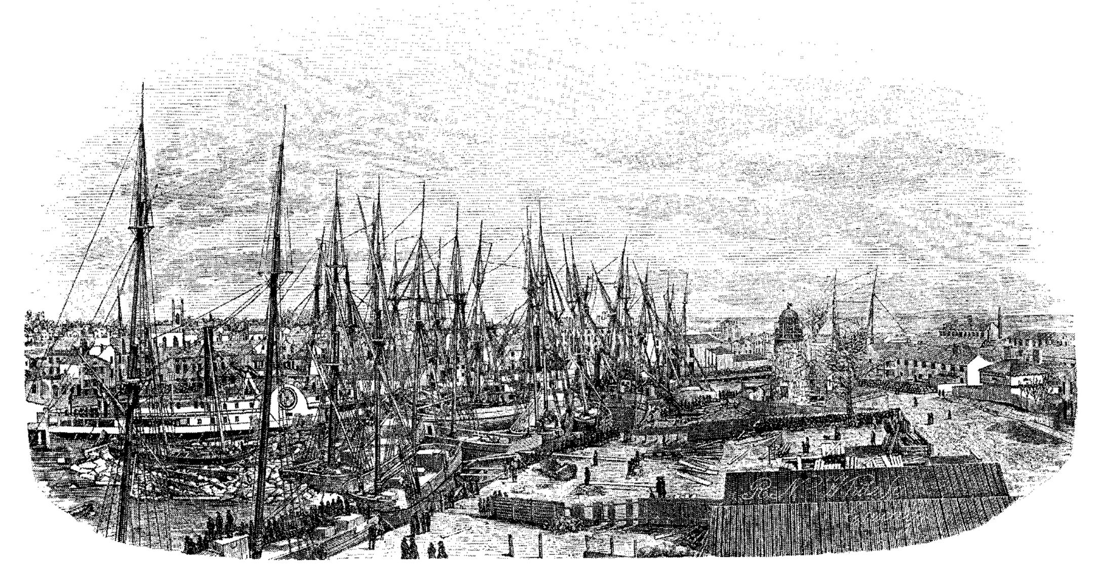
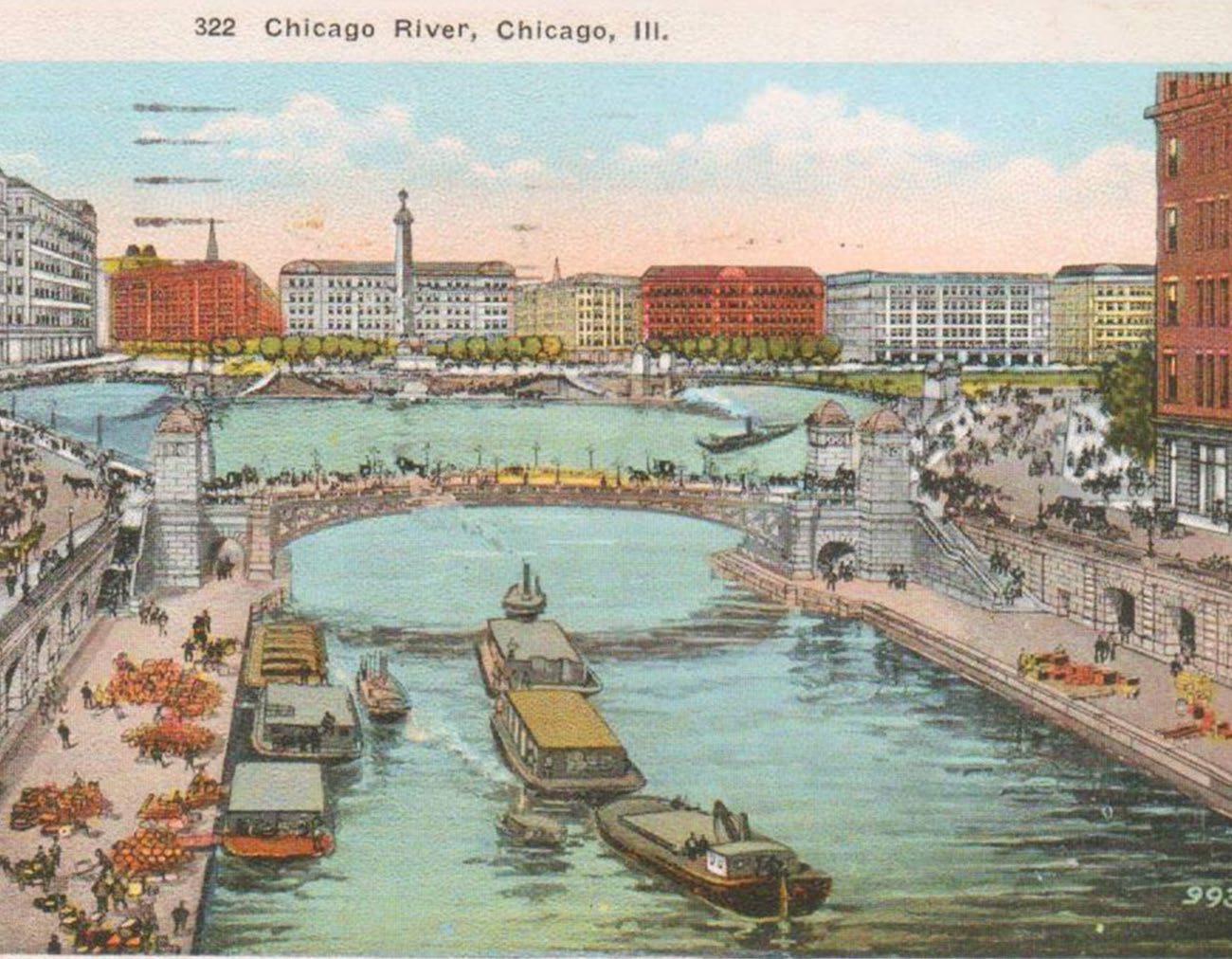
land by constructing Fort Dearborn in 1803 approximately where the Michigan Avenue Bridge intersects with Wacker Drive. The Fort proved to be a draw for further settlement in the area. Less than ten years later however, the War of 1812 pitted the local Native American tribes against the Americans which led to the residents of Fort Dearborn seeking to flee to a more protected region. It was during their attempted escape south to Fort Wayne, that the Potawatomi massacred almost a hundred people in the area around what is now 18th Street. After the battle, the Native Americans returned to the river and burned the fort to the ground. The site is now recognized as both a Chicago Landmark and a contributing location in the Michigan-Wacker National Register of Historic Places District. The outlines of where they believe the fort stood is indicated in bronze strips cast in the sidewalks of area. There is also a bas relief sculpture that depicts the battle carved in the limestone wall of the south eastern tender’s house of the Michigan Avenue Bridge.
Tensions continued between the surrounding Native American tribes and American settlers during the early 19th century and did not let up until the Native Americans were defeated in the Blackhawk war of 1832. The Chicago Treaty of 1833 permanently established U.S. control of all territory in Illinois. As a result, settlement rapidly increased and Chicago soon developed into a city.
Following the completion of the Illinois and Michigan Canal in 1848, which linked the Great Lakes to the Mississippi River and thereby to the Gulf of Mexico, the city quickly become a major transportation hub and the center for lumber and meat packing industries. The once bucolic river became an industrial zone with a series of warehouses and docks lining the river. Industrial and commercial waste was systematically dumped into the river. Since the river flowed into the lake, the source of the city’s drinking water, the excess pollution became a major public health concern as did outbreaks of typhoid fever and cholera. This concern led to a significant engineering feat to reverse the flow of the Chicago River so that sewage and other waste were diverted to the Des Plaines River and then the Mississippi River instead of Lake Michigan.
The 1909 Burnham Plan envisaged a riverfront free from the clutter and visual chaos of the numerous bridge styles, piers, docks, and buildings. Famed architect Daniel Burnham, who managed the construction of the 1893 World’s Columbian Exposition, and Edward H. Bennett were hired by a group of prominent businessmen to plan for the future of the City. As part of the plan, Burnham and Bennett called for aesthetic improvements to not only the riverfront but also the numerous bridges that the Plan recommended for more efficient transportation. Burnham and Bennett’s plan was heavily influenced by Beaux Arts classicism which was implemented in many of the new bridges, bridge houses and stairs, and the esplanade along the south side of Wacker Drive. Development took longer on the north side of the river, but it too was to be revamped. The beautification process attracted developers and businesses to locate their office buildings along the river, with some of the most significant buildings nestled at either end of the Michigan Avenue bridge. Industry, meatpacking, and wholesale companies were to eventually move away from the main stem of the river, which changed the nature of the river into the scenic tourist destination that it is today.
Although the city was a commercial and industrial hub, it also had a significant tourist and entertainment industry. Excursion boats often traveled along the lake and river. It was during one of these excursion trips in 1915 that the SS Eastland rolled over while docked between Clark Street and LaSalle Street, killing 844 passengers. The boat apparently had a history of being top-heavy and liable to list so when passengers flocked to one side of the upper levels, the boat quickly leaned over into the river, trapping many of those who were below deck. The event and site are now memorialized by a marker at LaSalle Street and Wacker Boulevard.


5.0
The Chicago River has played a significant role in the city’s history so it is not surprising that many significant events have occurred along the river. Important sites and events have been recognized by the city and National Park Service and are marked by plaques, sidewalk markers, and monuments. In addition, a Vietnam Veterans Memorial was constructed in 2005 along the river. The memorial is located at Wabash Avenue and Wacker Drive and designed by the firm Ross Barney + Jankowski Architects.
The proposed Skyline route is essentially along a highly urbanized corridor adjacent to Wacker Drive and the Riverwalk. It will be in close proximity to a variety of sites and monuments that are currently listed as City of Chicago Landmarks, or that have been graded as “red” or “orange” on the Chicago Historic Survey are shown in Figure 5.14 (“red” properties possess some architectural feature or historical association that made them potentially significant in the broader context City of Chicago, the State of Illinois, or the United States of America while orange properties are significant in the context only to the surrounding community) The map also identifies those sites along the route that are listed on the National Register of Historic Places or are part of a National Register District. The list included below provides an understanding of the existing cultural resources.
Chicago Landmark
• Heald Square Monument (Wacker Drive and Wabash Avenue)
Chicago Historic Resources Survey (Designated “Red”)
• DuSable House (401 N. Michigan Avenue)
• Fort Dearborn Site (333 N. Michigan Avenue)
Chicago Historic Resources Survey (Designated “Orange”)
• Eastland Disaster Site (124 W. Wacker Drive)
• Heald Square Monument (26-44 E Wacker Drive)
Contributing to the Michigan-Wacker Historic District
• Fort Dearborn Site (333 N. Michigan Avenue)
• Heald Square Monument (26-44 E Wacker Drive)
Potentially Contributing Sites or Markers
• First Post Office Marker
• Hubbard’s Folly Marker
• Vietnam Veterans Memorial
• First Movable Bridge Marker
Historic Architecture
The Chicago River, once a hub of industrial and warehouse buildings and docks, has been altered into a scenic and highly valuable location for commercial and residential development. Industry has long since been pushed beyond the Loop and the river was re-envisioned as far back as 1909, in the Burnham Plan, as a place of beauty. Both the Wacker Drive Esplanade and Michigan Avenue Bridge are products of this plan and were constructed during the 1920s.
The proposed Skyline route originates just to the south of the Navy Pier Head House, its primary route is through an architecturally dense and historic area along the main branch, from Michigan Avenue to Lake Street. A summary list and a graphic plan, provided at the end of this section, of the buildings that have been identified as a City of Chicago Landmark, “red” or “orange” on the Chicago Historic Survey, and/or listed on the National Register is provided below. In addition, buildings that have potential architectural significance but not yet recognized by city or federal authorities because of their more recent date, have also been identified below and in the graphic plan.
(See 7.0 Appendix for details)
1 Engineering Building, 205 W. Wacker Dr. (NR)
2 Builders Building, 222 N. LaSalle St. (NR)
3 LaSalle-Wacker Building, 221 N. LaSalle St. (CHRS, NR)
4 Eastland Boat Disaster Plaque (CHRS)
5 Jewelers’ Building, 35 E. Wacker Dr. (CL, CHRS, NR)
6 Seventeenth Church of Christ Scientist, 55 E. Wacker Dr.
7 Mather Tower, 75 E. Wacker Dr. (CL, CHRS, NR)
8 London Guarantee Bldg., 360 N. Michigan Ave. (CL, CHRS, NR)
9 Fort Dearborn Site (CL, CHRS, NR)
10 333 N. Michigan Ave. (CL, CHRS, NR)
11 One Illinois Center, 111 E. Wacker Dr.
12 Old Chicago Coast Guard Station (CL, CHRS)
13 Navy Pier Headhouse (CL, CHRS)
14 Lake Point Tower, 505 N. Lake Shore Dr.
15 Tribune Tower, 435 N. Michigan Ave. (CL, CHRS, NR)
16 DuSable Home Site (NR/NHL)
17 Wrigley Building, 410 N. Michigan Ave. (CHRS, NR)
18 IBM Plaza, 330 N. Wabash Ave. (CL)
19 Marina City, 300 N. State St.
20 Reid Murdoch Center, 320 N. Clark St. (CL, CHRS, NR)
21 Merchandise Mart, 222 Merchandise Mart Plaza (CHRS)


Chicago Landmark
• Jewelers’ Building (35 E. Wacker Drive)
• Mather Tower (75 E. Wacker Drive)
• 333 N. Michigan Avenue
• London Guarantee Bldg. (360 N. Michigan Ave.)
• Navy Pier Head house
• Tribune Tower (435 N. Michigan Avenue)
• IBM Plaza (330 N. Wabash Avenue)
• Reid Murdoch Center (320 N. Clark Street)
• Wacker Drive Esplanade (2-82 Wacker Drive)
Chicago Historic Resources Survey (Designated “Red”)
• Jewelers’ Building (35 E. Wacker Drive)
• London Guarantee Bldg. (360 N. Michigan Ave.)
• 333 N. Michigan Avenue
• Navy Pier Head house
• Tribune Tower (435 N. Michigan Avenue)
• Wrigley Building (410 N. Michigan Avenue)
• Reid Murdoch Center (320 N. Clark Street)
• Merchandise Mart (222 Merchandise Mart Plaza)
Chicago Historic Resources Survey (Designated “Orange”)
• Mather Tower (75 E. Wacker Drive)
• LaSalle-Wacker Building (221 N. LaSalle Street)
• Wacker Drive Esplanade (2-82 E Wacker Drive)
National Register of Historic Places
• Reid Murdoch Center (320 N. Clark Street)
Contributing to the Michigan-Wacker Historic District
• 333 N. Michigan Avenue
• London Guarantee Bldg. (360 N. Michigan Ave.)
• Jewelers’ Building (35 E Wacker Drive)
• Mather Tower (75 E. Wacker Drive)
• Tribune Tower (435 N. Michigan Avenue)
Contributing to the West Loop-LaSalle Street Historic District
• 222 N. LaSalle Street
• LaSalle-Wacker Building (221 N. LaSalle Street)
• 205 W. Wacker Dr.
Potentially Historically Significant Buildings
• Seventh Church of Christ Scientist (55 E. Wacker Drive)
• One Illinois Center (111 E. Wacker Dr.)
• Lake Point Tower (505 N. Lake Shore Dr.)
• Marina City (300 N. State St.)
Settlement along the Chicago River did not occur solely on one side. As the city developed, providing an efficient river crossing was essential to its physical and economic vitality. The construction of the Illinois and Michigan Canal also required that the new bridges be able open for boat passage. Early bridges, such as the floating swing bridges and center pier swing bridges restricted the size of the river traffic since they pivoted in the middle of the river. It was not until the development of the bascule bridge that a successful solution was found for both road and water navigation. The engineering aspects of bridge design continued to develop with different variations of the bascule bridge being implemented. These designs however, were not always the most visually appealing.
The 1909 Plan of Chicago called for aesthetically pleasing and efficient bridges to be installed across the river. These bridges would be in contrast to the chaotic assemblage of different bridge styles then in existence. The architectural aspects of the bridges (i.e., bridge houses, railings, stairways) were intended to complement the intended classical architecture featured in the Plan and be beautiful in their own right. Edward Bennett, co-author of the Plan of Chicago with Burnham, served as the architectural consultant for the Chicago Plan Commission and his Beaux Arts training certainly influenced the classically inspired designs of the bridges and associated architecture built between 1913 and 1930. The architectural aspects of later bridge designs changed with the change in styles, but the importance of creating architecturally pleasing bridges remained important.
The proposed Skyline route will go over the south portion of all of the bridges and their associated bridge houses and stairways down to the river along the main branch of the Chicago River. When noting historic bridges, it is not just the bridges that are important, but the entire assemblage of architectural elements that accompany it that were built at the same time and same style. It should be noted that there have been additional, nonoriginal, architectural elements added down to the river walks. These are not in character with the original stone bridges and should not be treated
as part of the bridge assemblage. A summary list and plan of the bridges identified as a City of Chicago Landmark, “red” or “orange” on the Chicago Historic Survey, and/or listed on the National Register is included below to better understand the existing cultural resources and their significance. In addition, bridge assemblies not yet given a historic designation, but still potentially historically significant are also identified.
Chicago Landmark
• Michigan Avenue Bridge (Note: the flagpoles are not original and not noted in the Landmark designation)
Chicago Historic Resources Survey (Designated “Red” or “Orange”):
• Franklin Street Bridge (Orange)
• Wells Street Bridge (Orange)
• LaSalle Street Bridge (Orange)
• Clark Street Bridge (Orange)
• Michigan Avenue Bridge (Red)
• Lake Shore Drive Bridge
Contributing to the Michigan-Wacker Historic District
• Michigan Avenue Bridge
Contributing to the West Loop-LaSalle Street Historic District
• LaSalle Street Bridge
Other Potentially Historically Significant Bridges
• Dearborn St. Bridge
• State St. Bridge
• Wabash Ave. Bridge
LaSalle Street
LaSalle Street is an important vehicular transportation route in-and-out of the Loop with traffic going both north-and-south. It consists of the views toward the river from both the north and south sides and is framed by the buildings on either side of the street. The West Loop-LaSalle Street Historic District’s northern boundary is the Chicago River and intersects with the Skyline corridor. The Skyline would provide views for one block between Lake Street and Wacker Drive. The view corridor looking north from the area south of Lake Street is blocked by the elevated rail system (The “L” tracks) that crosses over LaSalle Street along Lake.
Over the course of its 1.6 mile path along the main branch of the Chicago River there are a number of cultural resources that consist of significant monuments and memorials, buildings and esplanades, bridges and associated architecture, and view corridors that have been described above. In general, the Skyline infrastructure will strive to avoid being placed in direct contact or close proximity to any historically significant elements thereby rendering minimal or no adverse effect to any of those resources.
The proposed use of weathering steel for the pylons and other built elements has raised some concerns about the potential of staining of adjacent built elements. This is viewed as a solvable technical challenge and will be addressed as the design of the system moves forward to the next stage of development.
The Skyline will also have a positive visual impact along its course. It will run directly above the Wacker Drive Esplanade and in-front of many significant buildings. The infrastructure, pylons, stations, cables, and pods are being carefully designed in a fashion that will be seen as an exciting enhancement of the cultural views rather than being seen as additional visual clutter. The scale of Skyline is sculptural, full of light and air, as compared to the existing heavy solidity of the street wall along Wacker Drive. Chicago has always prided itself on making advancements in architecture and engineering that can be accomplished in a way that add to its urban beauty. This 21st century aerial cable car will be another example of the city’s forward thinking and embrace of modernity.
Air quality conformity is a mechanism that guides federal funding and approval to those transportation activities that are consistent with air quality goals as contained in the State Implementation Plans (SIPs). Once an area reaches attainment, the SIPs are amended to include a 10-year maintenance plan. Northeastern Illinois, including Cook County, where this project would be located, is currently in attainment of the standards for four of the six criteria pollutants: carbon monoxide, nitrogen dioxide, sulfur dioxide, and lead. Cook County is classified as a moderate non-attainment area for the 8-hour ozone standard, and a non-attainment area for the annual fine particulate matter (PM2.5) standard. As a result, the region has implemented a transportation program which will help to reduce levels of these pollutants to national standards.
Some individual transportation projects must be evaluated for local air quality impacts, commonly called a “hot spot analysis.” Projects that are subject to hot spot analysis are called, “projects of air quality concern.” They involve significant levels of diesel vehicle traffic, or are identified in a PM2.5 or PM10 State Implementation Plan as a localized air quality concern.
The Skyline would be powered by electricity, and would therefore not generate substantial emissions at the point of use. The system would be required to have back-up generators at stations. These back-up generators could be diesel or gas-powered, but the use would be limited and would therefore not be a substantial source of emissions. This project would not include the addition of roadway through lanes or auxiliary turning lanes, and should therefore be considered exempt from the need for Microscale Air Quality Assessments.
The project could generate 1.4 million new visitor trips to downtown Chicago per year. It is expected that less than half of those trips would arrive by automobile. Based on the preliminary traffic analysis performed in Section 5.1.1, the temporal and geographic distribution of these automobile trips would result in negligible traffic impacts. Therefore, the potential MSAT impacts would be low.
Construction activities can result in short-term increases in fugitive dust and equipment-related particulate emissions in and around the project area, but equipment-related particulate emissions can be minimized if the equipment is well maintained. The potential for fugitive dust emissions typically is associated with building demolition, ground clearing, site preparation, grading, stockpiling of materials, on-site movement of equipment, and transportation of materials. The potential is greatest during dry periods, periods of intense construction activity, and during high wind conditions.
The potential air quality impacts would be shortterm, occurring only while construction work is in progress and local conditions are appropriate. The contractor would be required to submit a Dust Control Plan for approval prior to beginning construction, and adhere to all federal, state, and local laws pertaining to dust control. With the application of appropriate measures to limit dust emissions during construction, this project will not cause significant, short-term particulate matter air quality impacts.
The project area is located in a heavily developed urban environment with numerous existing sound sources that contribute to the ambient or background noise. Major noise sources in the project area consist of roadway traffic, bus traffic, boat traffic, and a variety of commercial and residential neighborhood uses. Ambient noise levels influence the acceptability of additional noise sources. The nighttime hours, defined as 10:00 PM to 7:00 AM, are considered particularly sensitive as ambient noise levels tend to be lower during those hours.
Noise sources related to the operation of the Skyline project include localized noise at each station and movement of the pods along the corridor. According to the manufacturers of the proposed Skyline system (Leitner-Poma), the major equipment used to operate the Skyline would generate localized noise related to loading doors, direct drive motors, and the cable bullwheels. The interaction between the cable and the angle stations also generate noise. The anticipated normal operating hours for the system are from 11:00 AM to 10:00 PM on weekdays and from 10:00 AM to 10:00 PM on weekends.
Station locations are anticipated to be in areas of heavy urban noise activity. These include the Navy Pier Terminal station adjacent to Illinois Street and the other two stations adjacent to Wacker Drive. The noise sensitive land uses are generally located at least 200 to 300 feet from the proposed Skyline stations and pylons. Noise-sensitive land uses in the corridor include residential units, hotels, and institutional facilities including schools and churches. For noise sensitive land uses, building construction and distance from the noise source can provide appropriate screening or dispersion of the noise.
Noise reduction measures which should be considered include:
• Stations would be enclosed except where pods enter and exit the station, thus limiting the diffusion of noise at those locations.
• The motor at the drive station would be electric with no gear reducer.
• Stations would be located away from noise sensitive land uses.
• The system would not regularly operate during overnight hours.
With respect to construction noise, on-site construction is temporary and would be conducted within the noise guidelines established by the City of Chicago. There is a potential need for pile driving to construct the foundations for support pylons, but the detailed construction methods remain to be determined.
The Skyline project would be constructed mostly along the proposed Chicago Riverwalk, which is being extended along the south side of the Chicago River from State Street to Lake Street. The City of Chicago has applied for certifications or permits from the Illinois Environmental Protection Agency (IEPA), the Illinois Department of Natural Resources, and the Army Corps of Engineers regarding potential impacts to natural resources associated with the Riverwalk project. Natural resources include plant communities, wildlife resources, threatened and endangered species, state designated lands, water resources and aquatic habitats, groundwater, floodplains, and wetlands.
To date, the Army Corps of Engineers has determined that the proposed construction of the Riverwalk would not affect federally-listed endangered or threatened species or critical habitat for endangered or threatened species. Although no impacts are anticipated, updated coordination with the U.S. Fish and Wildlife Service will be required to incorporate the entire project area. The height of stations, pylons, and cables does not exceed the height of other structures in the downtown Chicago and should not have an impact on wildlife travel patterns.
Special waste includes hazardous waste, potentially infectious medical waste (PIMW), industrial process waste, and pollution control waste. Illinois regulates the disposal of special waste. In the past, the river bottom of the Chicago River has been found to contain toxins, a potential special waste. A Preliminary Environmental Site Assessment (PESA) is recommended to be completed as a part of the Environmental Assessment for the Chicago Skyline project. A PESA includes a detailed evaluation of available records dealing with the history of a site, and a field inspection and assessment of conditions at the site to identify Recognized Environmental Conditions (RECs). RECs include known releases or the potential for releases of regulated substances into the ground, groundwater, surface water, or structures on a site. If RECs are found, additional localized investigations may be required.
Special lands generally include publicly-owned parks, recreational areas, wildlife and waterfowl refuges, forest preserves, and historic sites. (See Figure 5-15). Special lands are protected by Section 4(f) of the Department of Transportation (DOT) Act of 1966, Section 6(f) of the Land and Water Conservation Fund Act of 1965 (LAWCON), and the Illinois Open Space Lands Acquisition and Development (OSLAD) Program.
The Chicago Skyline would be constructed from Gateway Park west of Navy Pier, across the Chicago River with one transfer structure near the northeastern tip of Grant Park, and then along the Riverwalk on the south side of the Chicago River. This would decrease the amount of space available along the Riverwalk, but would also add a new recreational amenity. Coordination will be required with the Chicago Department of Transportation regarding potential Section 4(f) concerns.

Grant Park is a publicly owned park that is protected under Section 4(f) as well as the Lake Michigan and Chicago Lakefront Protection Ordinance (Chapter 16-4 of the Municipal Code of Chicago). The Skyline would require one transfer structure to be constructed above the northeast corner of Grant Park adjacent to the Chicago River. The transfer structure support would be constructed on what is now open grass space. The support structure would be designed to minimize any impacts. Coordination would be required with the Chicago Park District regarding potential Section 4(f) concerns. The Lake Michigan and Chicago Lakefront Protection Ordinance would also require an application to be filed with the Chicago Plan Commission, a public hearing to be held, and notification provided to all property owners within 250 feet of the subject property.
In addition to the facilities discussed above, the Skyline would be visible from DuSable Park, River Esplanade Plaza, and the section of Grant Park east of Lake Shore Drive and north of Randolph Street. DuSable Park is reclaimed land that has undergone site remediation, but remains undeveloped. Riverside Esplanade Plaza Park is a 920 foot long section of tree-lined sidewalk along the north side of the Chicago River, with outdoor seating and a fountain. This section of Grant Park is primarily grass open space with sidewalks along the water and a connection between the Riverwalk and the Lakefront Trail. Coordination will be required with the Chicago Park District regarding potential 4(f) concerns.


The Skyline route will pass through a number of significant view corridors. The view corridors are defined as publically accessible views that are aesthetically and/or historically important to the character of the city. The corridors consist not only of popular tourist routes but also those major vehicular transportation roads to-and-from the Loop that are wider and go both north-and-south. The following are the some of the significant view corridors (see Figure 5-16):
• Wacker Drive/River
• Michigan Avenue
• From Lake Michigan toward the city
Wacker Drive/River
For the purpose of this report, the Wacker Drive/ Riverfront view corridor consists of the main Skyline route from the mouth of the river to approximately Lake Street. It is framed by the buildings to the north and south and is best experienced while on the river or one of the bridges, but is also from the riverfront walks and restaurants on either side on the river, from Wacker Drive and from the surrounding buildings.
Michigan Avenue
Michigan Avenue is perhaps the most famed street in Chicago, and is particularly popular with tourists going between the Loop and the Magnificent Mile. The Michigan Avenue view corridor consists of the views toward the river from both the north and south sides and is framed by buildings on either side of Michigan Avenue. Michigan Avenue, which intersects with Wacker Drive is a wide street with vehicle traffic going both north and south. The Skyline will provide additional views from both the north and the south approaches to the intersection of Michigan Avenue and Wacker Drive.
State Street
State Street is another tourist destination street in the Loop and an important vehicular transportation route with traffic going both north and south. It consists of the views toward the river from both the north and south sides and is framed by the buildings on either side of the street. The Skyline will be visible to those on the north side of the river but pedestrians to the south of Lake Street, who are looking north, will have a partially obstructed view because of the “L.” The “L” is Chicago’s rapid transit train system in which some of the train lines run on an elevated track that loops through the Chicago’s downtown. A section of the Loop runs along Lake Street with a highly trafficked “L” station at State Street and Lake Street. The tracks and station will inhibit clear views of the Skyline from the major historic retail area to the south. This retail area is part of the Loop Retail Historic District which is bounded by State Street to the west, Wabash Avenue to the east, Lake Street to the north, and Congress Parkway to the south. The district is a major tourist area and comprises many of the city’s historically important department store buildings.
Environmental Resource
Transportation
Social/ Economic
The project would generate additional automobile trips to downtown, but additional congestion is not expected. Sidewalk capacity would not be exceeded and no significant queuing is expected on sidewalks, paths, or roadways as a result of Skyline. ADA access to the Riverwalk would be improved.
The project is compatible with existing land uses and would improve linkages between communities. Increased economic activity and new jobs are anticipated. There would be no significant impacts related to environmental justice.
Cultural Alternatives have been developed which avoid direct impact to known cultural resources. However, the project corridor is potentially within the view shed of properties eligible for or on the National Register of Historic Places. These sites will require further evaluation and possible visual mitigation.
Air Quality
No significant adverse impacts
Noise
Natural Resources
Special Waste
Localized noise is anticipated at each station and transfer structures. There would also be short term noise related to construction.
N/A
Special Lands/ Section 4(f)/6(f)
No adverse impacts to endangered or threatened species or critical habitats are anticipated as part of the Skyline project.
N/A
Visual Resources
A Preliminary Environmental Site Assessment is recommended as part of future environmental documentation to identify Recognized Environmental Conditions.
The Skyline would occupy space along the Riverwalk, but would also complement its use as a tourist destination, and attract visitors. A transfer structure would be required in an underutilized section of Grant Park. The Skyline would also be visible from several additional parks, requiring analysis of visual impacts.
The Skyline will provide a new opportunity to view the architectural significance of the river corridor. Design qualities will be established at each station, which complements the diversity of the architecture along the urban corridor.
Evaluation of cultural resources required. Alternative adjustments and aesthetics improvements to minimize impact to potential historic properties are likely.
N/A
Shielding of localized noise. Schedule construction in accordance w/ City requirements to minimize community disruption.
Preliminary Site Investigations may be required for specific sites.
Not adverse; Improved ADA accessibility to riverfront
Not adverse
Not adverse or De minimis
Not adverse
Not adverse
Not adverse
Preliminary Site Investigations may be required for specific sites.
Coordination with the Chicago Park District, Chicago Department of Transportation, and Chicago Plan Commission required.
Establish a station and transfer structure design criteria that is complementary to the urban corridor.
Not adverse
Not substantially adverse
Not substantially adverse
See Table 5-18: Environmental Impact Summary.
As described above, the proposed Chicago Skyline Project requires additional environmental analyses, particularly for maintenance of traffic, cultural resources, natural resources, noise, views, hazardous materials, and Section 4(f)/6(f). A summary of the preliminary impact findings is presented in Table 5-18.
Applications to the following organizations may be required in order to obtain permits to construct the Chicago Skyline project:
• The US Army Corps of Engineers for work in the Chicago River pursuant to Section 10 of the Rivers and Harbors Act of 1899 (33 U.S.C. 403) and Section 404 Action of the Clean Water Act of 1972 (33 U.S.C. 1344)
• The Illinois Environmental Protection Agency (IEPA) for water quality certification, or waiver thereof, for the proposed activity in accordance with Section 401 of the Clean Water Act
• The Illinois Department of Natural Resources, Office of Water Resources (IDNR-OWR) for a permit pursuant to the State of Illinois Rivers, Lake and Streams Act (615 ILCS 5)
• The USCG for a Bridge Permit to construct a crossing over the Chicago River, which is a navigable waterway
• Zoning including aldermanic approval
• The City of Chicago for building permits for all three proposed stations, transfer structures & pylons, public way use permits, and various construction-related permits (e.g., street/ sidewalk opening permits, scaffolding permits, street closure permits)
• The Chicago Plan Commission for construction in Grant Park in accordance with the Lake Michigan and Chicago Lakefront Protection Ordinance
• The CDOT Deep Foundation Permits
• The City of Chicago Traffic Permit for any temporary and/or permanent lane closures on lower and Upper Wacker Drive
• Chicago Department of Water Management
Permit for new sewer/drainage work
• Chicago Department of Water Management
Permit for permission to temporarily draw water from hydrants for construction use
• City Council
Implementation of the proposed Chicago Skyline project would require regulatory permits from two federal agencies: the US Army Corps of Engineers and the USCG. These discretionary actions would trigger an environmental review under NEPA.
This feasibility study has not identified any potential significant adverse impacts on the human environment that would require the preparation of an environmental assessment or an environmental impact statement. Therefore, it is expected that the Skyline could be processed as a categorical exclusion with additional documentation for unusual conditions associated with certain environmental resource areas. Coordination with the Federal Regulatory Agency will help to determine the environmental class of action for this project.
It is assumed that the environmental documentation for the proposed Chicago Skyline project would be in the form of a categorical exclusion led by CDOT in cooperation with the Army Corps of Engineers as the regulatory agency. With an aggressive schedule and no major public controversy, this work could be completed in approximately 12 months. An estimated timeline is presented in Table 5-19, opposite. This timeline does not include the time required to obtain the actual permits discussed in Section 5.2.
Project Description
Purpose and Need
Alternatives
Design Characteristics
Right-of-Way / Property
Utility Involvement
Environmental Features
Transportation
Ecological Resources
Cultural Resources
Hazardous Materials
Section 4(f)/6(f) Resources Air
Community Impacts
Public
Pending Assets Aloft approval of this report, the Skyline design team shall move forward into the next phase of design documentation. Beginning with schematic design and ending in bid documentation, we estimate that this phase shall last approximately 15 months. We have outlined the following “Next Steps” as critical considerations moving forward for the upcoming stages of the project’s development:
• Conduct detailed survey of existing underground utilities and infrastructure, along the route’s entirety, as they relate to foundation planning and design.
• Initiate the environmental review process by determining the governing agency for the project and the required documentation effort.
• Initiate in-depth analysis of the existing conditions along the route and the various locations in which the Skyline interfaces with historic structures and/or landmarks or special lands. This effort will focus primarily on the transfer structures at Michigan Avenue and Wabash Avenue given the limited area available to locate the transfer structures in the Riverwalk.
• Advance coordination with the Chicago Riverwalk project and CDOT regarding incorporation of Skyline foundation areas in the construction documents for Rooms 1, 2 and 3 that are currently planned for construction in 2014. Further design coordination will be needed regarding the Riverwalk design and construction at rooms 4, 5, and 6.
• Formulate a clear sustainable design strategy and goals for the Skyline which might include but is not limited to:
– Sustainable Site Development
(Bike storage, stormwater management systems, maximization of open space and community connectivity)
– Water Efficiency
(Efficient landscaping technologies, innovative wastewater management systems, water use reduction)
– Energy and Atmosphere
(Optimizing energy performance, on-site renewable energy, green power)
– Materials and Resources
(Storage and collection of recyclables, construction waste management, materials re-use, regional materials, rapidly renewable materials, and recycled content)
– Indoor Environmental Air Quality
(Increased ventilation, low-emitting materials & finishes, system controls, daylighting & views
– Innovation and Design Process
– Regional Priority
• Develop Construction Methods and Timeframes.
• Acquire Developer Services to assist with Permitting and Approval processes.


• AECOM. 2012. Chicago Skyline Project Report [AECOM Project No. 60282030). February.
• Chicago Department of Transportation (CDOT). 2006. Chicago Traffic Tracker. Available at: http://webapps.cityofchicago.org/traffic/. Accessed May 2, 2013.
• Chicago Metropolitan Agency for Planning (CMAP). 2013. tg_300_2020_c13Q1.xlsx, socec_history.zip [Socioeconomic history data and projections]. March 6.
• Chicago Transit Authority (CTA). 2011. RBS_ STOP.shp [GIS bus stop ridership data]. July 22.
• Geo Services, Inc. 2011. Geotechnical Report Chicago Riverwalk State Street to Lake Street (CDOT Project No. E-O-621). October.
• Illinois Department of Transportation (IDOT ). 2010. Traffic Count Database System. Available at: http://www.ms2soft.com/tcds/ tsearch.asp?loc=Idot&mod=TCDS. Accessed May 2, 2013.
• Traffic Analysis and Design (TADI). 2011. Navy Pier Master Plan, Hourly Volume Summary, Illinois Street and Streeter Drive/Lake Shore Drive Off-Ramp. May 7.
• Walker Parking Consultants. 2006. Aqua Development Traffic Analysis Study. July.
• Transportation Research Board of the National Academies. 2010. Highway Capacity Manual, Chapter 4.3, Capacity Concepts.
• AECOM. “Chicago Skyline Sensitivity Test Without State Street Station.” memorandum. June 3, 2013
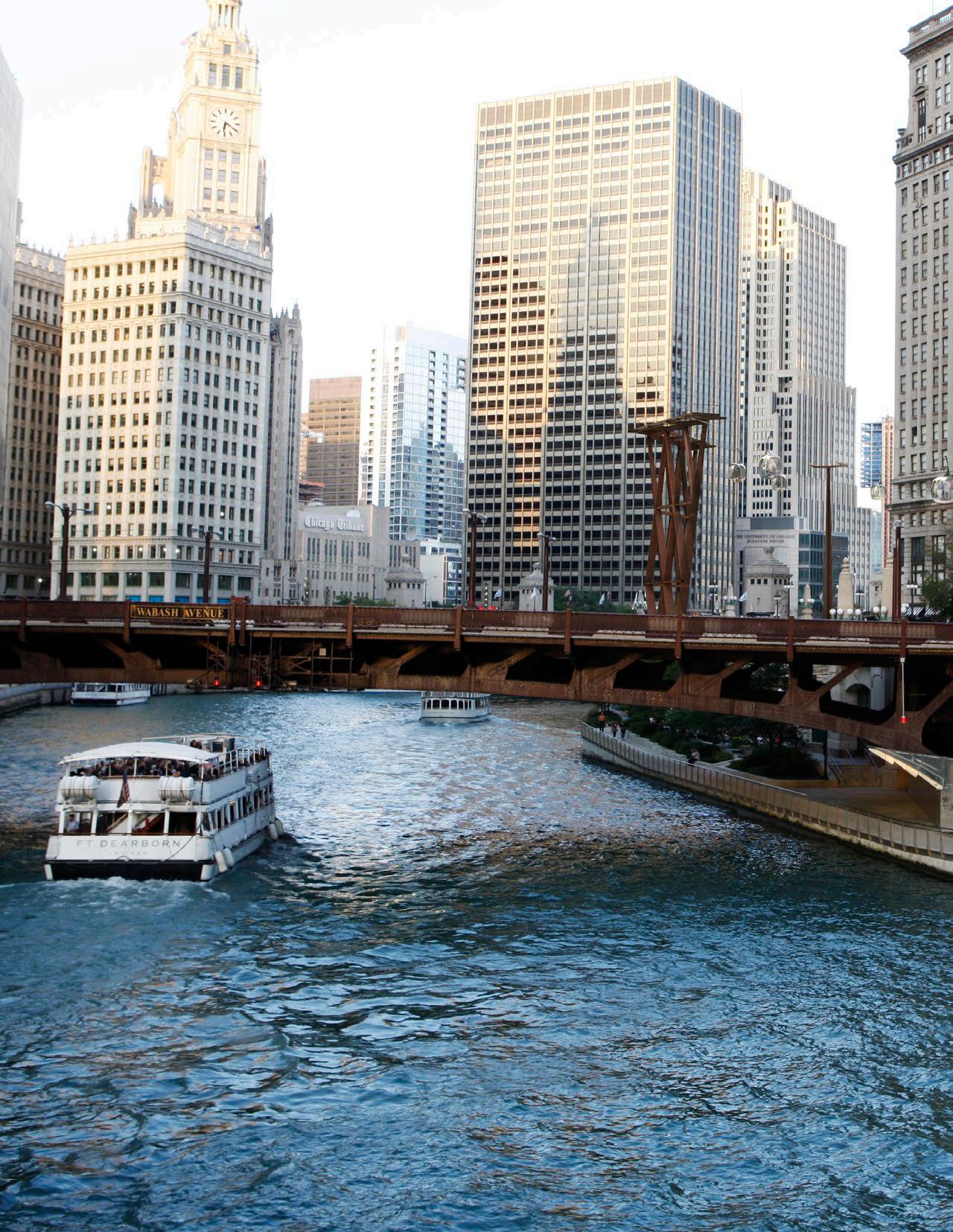
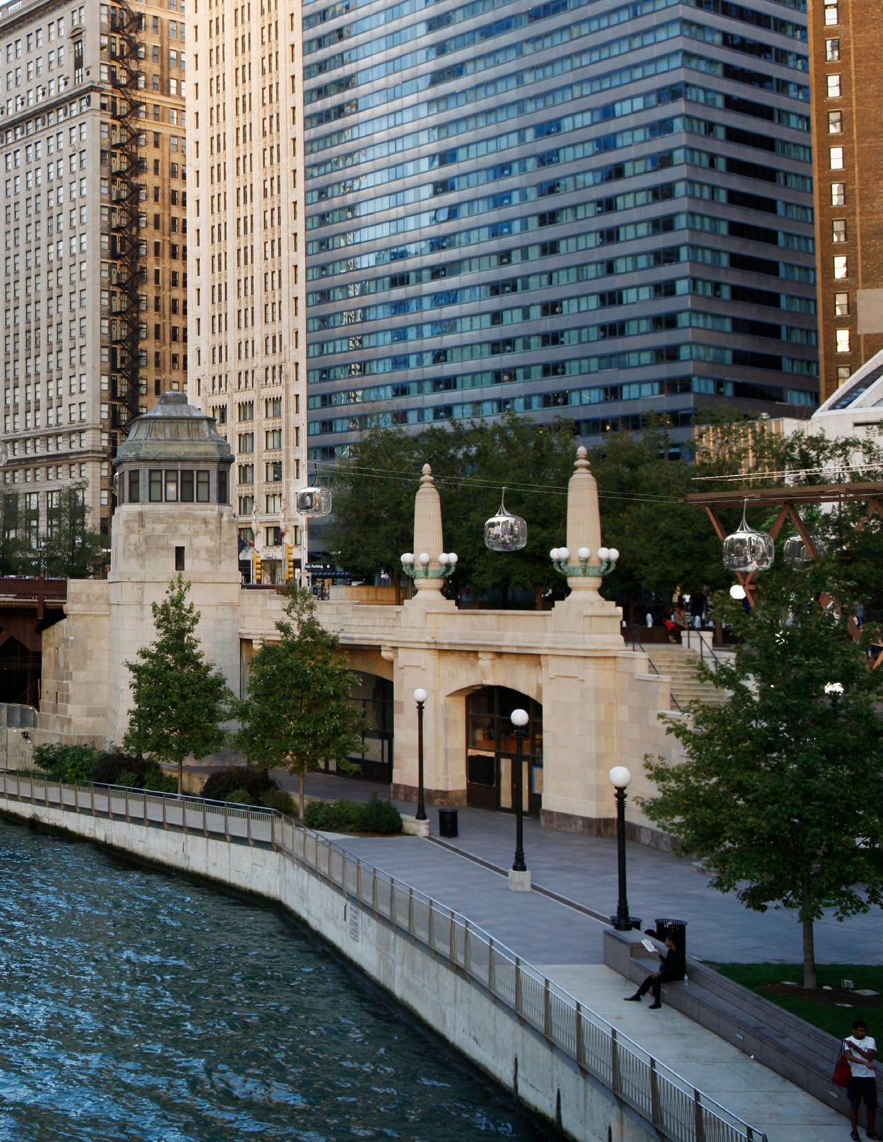
BUILDING/BRIDGE/MARKER
Keynote Number: 1
Building Name:
Engineering Building (Original Name)
Address:
Address:
Address 205 W. Wacker Drive
205 W. Wacker Dr.
Original Architect Burnham Brothers
Original Architect: Burnham Brothers
Approx. Construction Date 1928
Approx.
Building Name:
Builders Building
Address: 222 N. LaSalle St.
Original Architect: Graham, Anderson, Probst, & White
Address 222 N. LaSalle Street
Approx. Construction Date: 1927
Original Architect Graham, Anderson, Probst, & White
Approx. Construction Date 1927
Historic Significance Designations:
• Contributing building to the West Loop LaSalle Street NR Historic District
Historic Significance Designations
Approx. Construction Date: 1928
Contributing building to the West Loop - LaSalle Street
Historic
•
NR Historic District
Historic Significance Designations:
• Contributing building to the West Loop LaSalle Street NR Historic District
Historic Significance Designations
Contributing building to the West Loop - LaSalle Street
NR Historic District
Keynote Number:
3 Building Name: LaSalle Wacker Building
Address:

221 N. LaSalle St.
Original Architect: Holabird and Root; Andrew Rebori
Address 221 N. LaSalle Street
Approx. Construction Date: 1930
Original Architect Holabird and Root; Andrew Rebori
Approx. Construction Date 1930
Historic Significance Designations:

Keynote
Site
Address:
Keynote Number: 4
Site Name: Eastland Disaster
Address Wacker Drive and LaSalle Street
Address:
Approx. Date 1915
Wacker Dr. and LaSalle St.
Historic Significance Designations
Approx. Date: 1915
Approx. Date: 1915
City of Chicago Historic Marker
• Orange rated on Chicago Landmarks Historic Resources Survey
Historic Significance Designations
• Contributing building to the West Loop LaSalle Street NR Historic District
•
• Orange rated on Chicago Landmarks Historic Resources Survey
• Contributing building to the West Loop-LaSalle Street NR Historic District

Historic Significance Designations: • City of Chicago Historic Marker
Historic Significance Designations:
• City of Chicago Historic Marker


Address:
Building Name: Jewelers’ Building
Address:
Building Name:
Jewelers’ Building
Address:
35 E. Wacker Dr.
35 E. Wacker Dr.
Original Architect: Giaver & Dinkelberg
Original Architect: Giaver & Dinkelberg
Approx. Construction Date: 1926
Address 35 E. Wacker Drive
Approx. Construction Date: 1926
Original Architect Giaver & Dinkelberg
Historic Significance Designations:
Historic Significance Designations:
Approx. Construction Date 1926
• Chicago Landmark (2007)
• Chicago Landmark (2007)
• Red rated on Chicago Landmarks Historic Resources Survey
Keynote Number: 6
Keynote Number: 6
Building Name:
Building Name:
Address 55 E. Wacker Drive
Seventeenth Church of Christ Scientist
Seventeenth Church of Christ Scientist
Address:
Address:
Original Architect Harry Weese & Associates
55 E. Wacker Dr.
55 E. Wacker Dr.
Approx. Construction Date 1968
Historic Significance Designations
• Red rated on Chicago Landmarks Historic Resources Survey
• Contributing Building to the Michigan-Wacker NR Historic District and listed separately on the NR.
Original Architect: Harry Weese & Associates
Original Architect: Harry Weese & Associates
Potential Building for Historic Designation
• Contributing Building to the Michigan-Wacker NR Historic District and listed separately on the NR.
• Chicago Landmark (2007)
• Red rated on Chicago Landmarks Historic Resources Survey
• Contributing Building to the Michigan-Wacker NR Historic District and listed separately on the NR.
Number:
Name:
Tower
Wacker Dr.
Approx. Construction Date: 1968
Approx. Construction Date: 1968
Potential Building for Historic Designation
Potential Building for Historic Designation
Keynote Number:
7
Building Name:
Mather Tower
Address:

BUILDING/BRIDGE/MARKER


75 E. Wacker Dr.
Architect:
Original Architect:
Hugh Riddle
Herbert Hugh Riddle
Construction Date:
Approx. Construction Date: 1928
Address 75 E. Wacker Drive
Significance Designations:
Historic Significance Designations:
Chicago Landmark (2001)
• Chicago Landmark (2001)
Original Architect Herbert Hugh Riddle
Orange rated on Chicago Landmarks Historic Resources Survey
• Orange rated on Chicago Landmarks Historic Resources Survey
Approx. Construction Date 1928
Contributing Building to the Michigan-Wacker NR Historic District
• Contributing Building to the Michigan-Wacker NR Historic District
Historic Significance Designations
• Chicago Landmark (2001)
• Orange rated on Chicago Landmarks Historic Resources Survey
• Contributing Building to Michigan-Wacker NR Historic District

Keynote Number: 8
Keynote Number: 8
Building Name: London Guarantee Building
Building Name: London Guarantee Building
Address:
Address: 360 N. Michigan Ave.
360 N. Michigan Ave.
Original Architect: Alfred Alschuler
Original Architect: Alfred Alschuler
Address 360 N. Michigan Avenue
Approx. Construction Date: 1923
Approx. Construction Date: 1923
Original Architect Alfred Alschuler
Approx. Construction Date 1923
Historic Significance Designations:
Historic Significance Designations:
• Chicago Landmark (1996)
• Chicago Landmark (1996)
Historic Significance Designations
• Red rated on Chicago Landmarks Historic Resources Survey
• Red rated on Chicago Landmarks Historic Resources Survey
• Chicago Landmark (1996)
• Contributing Building to the Michigan-Wacker NR Historic District

• Red rated on Chicago Landmarks Historic Resources Survey
• Contributing Building to the Michigan-Wacker NR Historic District
• Contributing Building to Michigan-Wacker NR Historic District
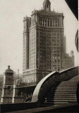
 1920s photo of the Jewelers’ Building (Chicago Daily News Archive)
Current photo of the Jewelers’ Building
Circa 1970 photo of church (Photo from the book The Architecture of Harry Weese)
Current photo of the church
Historic photo of Mather Tower on the right (source unknown)
Current photo of Mather Tower on the right
Historic photo of the London Guarantee Building (source unknown)
Address:
Michigan and Wacker Dr.
333 N. Michigan Avenue
Original Architect:
Original Architect:
Holabird & Roche/Holabird & Root
Holabird & Roche/Holabird & Root
Significance Designations:
Date of Event: 1812
Landmark (1971)
Approx. Construction Date: 1928
Approx. Construction Date: 1928
Historic Significance Designations:
Address Michigan and Wacker Drive
Chicago Landmarks Historic Resources Survey
Historic Significance Designations:
Historic Significance Designations:
Address 333 N. Michigan Avenue
• Chicago Landmark (1997)
• Chicago Landmark (1997)
Date of Event 1812
• Chicago Landmark (1971)
Site in the Michigan-Wacker NR Historic District
• Red rated on Chicago Landmarks Historic Resources Survey
• Red rated on Chicago Landmarks Historic Resources Survey
Historic Significance Designations
Original Architect Holabird & Roche/Holabird & Root
• Red rated on Chicago Landmarks Historic Resources Survey
• Contributing Building to the Michigan-Wacker Historic District
• Contributing Building to the Michigan-Wacker Historic District
Approx. Construction Date 1928
• Chicago Landmark (1971)
• Contributing Site in the Michigan-Wacker NR Historic District
• Red rated on Chicago Landmarks Historic Resources Survey
• Contributing Site in the Michigan-Wacker NR Historic District
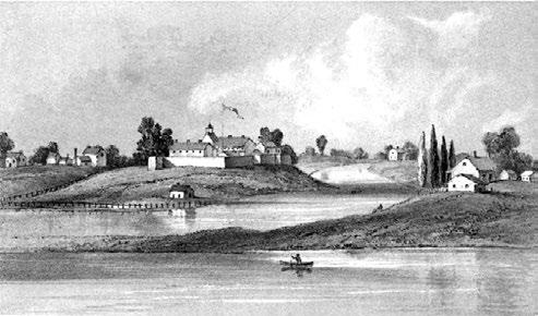
/BRIDGE/MARKER INFORMATION SHEET
Rendering of Fort Dearborn in 1831 (Rendering
Keynote Number: 12
Number:
Dearborn in 1831 (Rendering from book Wau Bun North-West)
Name: Center
Wacker Dr.
Architect: Rohe
Construction Date:
Historic Significance Designations
• Chicago Landmark (1997)
• Red rated on Chicago Landmarks Historic Resources Survey
• Contributing Building to the Michigan-Wacker Historic District


Building Name: Old Chicago Coast Guard Station
Address:
Lake Michigan near the mouth of the Chicago River
Address 111 E. Wacker Dr.
Original Architect Mies van der Rohe
Original Architect: Civil Engineers Office, US Coast Guard
Approx. Construction Date 1970
Building for Historic Designation
Potential Building for Historic Designation
Approx. Construction Date: 1936
Historic Significance Designations:
• Chicago Landmark (2007)
/BRIDGE/MARKER
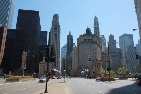
Old Chicago Coast Guard Station
Address:
Lake Michigan near the mouth of the Chicago River
Original Architect: Civil Engineers Office, US Coast Guard
Approx. Construction Date: 1936
Address Lake Michigan near the mouth of the Chicago River
Historic Significance Designations:
Original Architect Civil Engineers Office, US Coast Guard
• Chicago Landmark (2007)
• Orange rated on Chicago Landmarks Historic Resources Survey
Approx. Construction Date 1936
Historic Significance Designations
Chicago Landmark (2007)
Orange rated on Chicago Landmarks Historic Resources Survey13
• Orange rated on Chicago Landmarks Historic Resources Survey

Current

 from book Wau the “Early Day” in the North-West)
Site of Fort Dearborn Chicago Landmark’s Plaque.
1951 photo of 333 N. Michigan Ave. building on the left (The National Archives)
Current photo of the 333 N. Michigan Ave. building (on the left)
Original Architect: Charles S. Frost
Keynote Number: 14
Building Name:
Approx. Construction Date: 1916
Historic Significance Designations:
• Chicago Landmark (1977)
Address 35 E. Wacker Dr.
Original Architect Charles S. Frost
Approx. Construction Date 1916
Historic Significance Designations
• Chicago Landmark (1977)
Address:
Original Architect: Schipporeit and Heinrich
Approx. Construction Date: 1969
Address 505 N. Lake Shore Drive
Original Architect Schipporeit and Heinrich
Approx. Construction Date 1969
Potential Building for Historic Designation
• Red rated on Chicago Landmarks Historic Resources Survey

Keynote Number: 15
BUILDING/BRIDGE/MARKER
Building Name:
Tribune Tower
Keynote Number: 15 Building Name: Tribune Tower
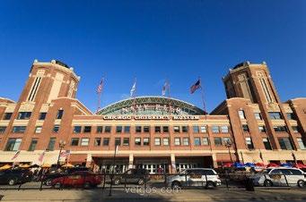
Address: 435 N. Michigan Ave
Address: 435 N. Michigan Ave
Original Architect: Howells & Hood
Original Architect: Howells & Hood
Approx. Construction Date: 1925
Address 435 N. Michigan Ave.
Approx. Construction Date: 1925
Historic Significance Designations:
Original Architect Howells & Hood
• Chicago Landmark (1989)
Historic Significance Designations:
Current
Potential Building for Historic Designation

BUILDING/BRIDGE/MARKER INFORMATION SHEET
Keynote Number: 16
Site Name:
Address 401 North Michigan Avenue
DuSable (Jean Baptiste Point) Homesite
Approx. Date 1779
Address:
401 North Michigan Avenue
• Red rated on Chicago Landmarks Historic Resources Survey
Approx. Construction Date 1925
• Chicago Landmark (1989)
• Contributing Building to the Michigan-Wacker NR Historic District
Historic Significance Designations
• Contributing Building to Michigan-Wacker NR Historic District
Historic Significance Designations
• Red rated on Chicago Landmarks Historic Resources Survey
Approx. Date: 1779
• National Historic Landmark (1977)
• Chicago Landmark (1989)
• Contributing Building to the Michigan-Wacker NR Historic District
• Red rated on Chicago Landmarks Historic Resources Survey
• Contributing Building to Michigan-Wacker NR Historic District
Historic Significance Designations:
• Contributing Building to the Michigan-Wacker NR Historic District
• National Historic Landmark (1977)
 1921 Photo of the Navy Pier Head Tribune
photo of the Navy Pier Head
Keynote
Building Name:
Address: 410 N. Michigan Ave
Address 410 N. Michigan Ave.
Original Architect Graham, Anderson, Probst, & White
Original
Original Architect: Graham, Anderson, Probst, & White
Approx. Construction Date 1924
Approx. Construction Date: 1924
Historic Significance Designations
Keynote Number: 18
Building Name:
IBM Building
Address:
330 N. Wabash Ave
Original Architect:
Mies van der Rohe
Approx. Construction Date: 1973
Address 330 N. Wabash Ave.
Original Architect Mies van der Rohe
Approx. Construction Date 1973
Historic Significance Designations:
• Red rated on Chicago Landmarks Historic Resources Survey
• Contributing Building to Michigan-Wacker NR Historic District
• Chicago Landmark (2008)
Historic Significance Designations
• Chicago Landmark (2008)
• Listed on the National Register of Historic Places (2010)
• Listed on the National Register of Historic Places (2010)
Historic Significance Designations:
• Red rated on Chicago Landmarks Historic Resources Survey
• Red rated on Chicago Landmarks Historic Resources Survey
• Contributing Building to the Michigan-Wacker NR
• Contributing Building to the Michigan-Wacker NR Historic District

Keynote
Address:
Address 300 N. State St.
Original Architect:
Original Architect Bertrand Goldberg
Approx. Construction Date: 1964
Approx. Construction Date 1964
Potential Building for Historic Designation

Potential Building for Historic Designation


BUILDING/BRIDGE/MARKER
Address 320 N. Clark St.
Keynote Number: 20
Keynote Number: 20
Original Architect George Nimmons
Building Name:
Building Name: Reid, Murdoch & Co. Building
Reid, Murdoch & Co. Building
Approx. Construction Date 1914
Address:
Historic Significance Designations
Address: 320 N. Clark St.
320 N. Clark St.
• Chicago Landmark (1976)
• Red rated on Chicago Landmarks Historic Resources Survey
Original Architect: George Nimmons
• Listed on the National Register of Historic Places (1975)
Original Architect: George Nimmons
Approx. Construction Date: 1914
Approx. Construction Date: 1914
Historic Significance Designations:
Historic Significance Designations:
• Chicago Landmark (1976)
• Chicago Landmark (1976)
• Red rated on Chicago Landmarks Historic Resources Survey
• Listed on the National Register of Historic Places (1975)
Red rated on Chicago Landmarks Historic Resources Survey Listed on the National Register of Historic Places (1975)
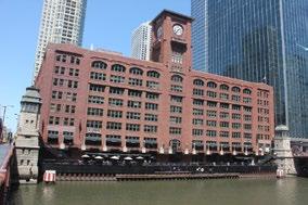
Address 222 Merchandise Mart Plaza
Original Architect Graham, Anderson, Probst & White
Approx. Construction Date 1930
Historic Significance Designations
Red rated on Chicago Landmarks Historic Resources Survey
Keynote Number: 22
Bridge Name:
Lake St. Bridge
Location:
BUILDING/BRIDGE/MARKER
Location Spans the Chicago River at Lake Street
Keynote Number: 22
Bridge Type Double deck, fixed trunnion bascule bridge
Bridge Name:
Spans the Chicago River at Lake St.
Approx. Construction Date 1916
Bridge Type:
Historic Significance Designations
Double deck, fixed trunnion bascule bridge
Spans the Chicago River at Lake St. Bridge Type:
Orange rated on Chicago Landmarks Historic Resources Survey
Approx. Construction Date: 1916
Historic Significance Designations:
Approx. Construction Date: 1916
• Orange rated on Chicago Landmarks Historic Resources Survey
Historic Significance Designations:
Orange rated on Chicago Landmarks Historic Resources
Landmarks Historic Resources Survey
BUILDING/BRIDGE/MARKER
Keynote Number:
Keynote Number:
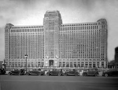


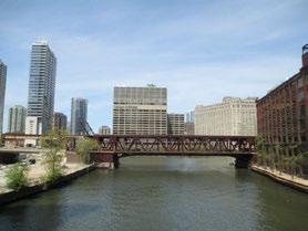

Bridge Name: Franklin St. Bridge
Location:
Bridge Name:
Location:
Spans the Chicago River
Spans the Chicago River
Bridge Type: Trunnion bascule bridge
Bridge Type: Trunnion bascule bridge
Location Spans the Chicago River
Approx. Construction Date: 1920
Approx. Construction Date: 1920
Bridge Type Trunnion bascule bridge
Approx. Construction Date 1920
Historic Significance Designations:
Historic Significance Designations:
Historic Significance Designations
• Orange rated on Chicago Landmarks Historic Resources Survey
BUILDING/BRIDGE/MARKER
Location Spans the Chicago River at Wells Street
Keynote Number: 24
Keynote Number: 24
Bridge Type Double deck bascule bridge
Bridge Name:
Wells St. Bridge
Bridge Name: Wells St. Bridge
Approx. Construction Date 1922 (bridge rebuilt in 2013)
Location:
Location:
Historic Significance Designations
Orange rated on Chicago Landmarks Historic Resources Survey
• Orange rated on Chicago Landmarks Historic Resources Survey
Spans the Chicago River @ Wells St.
Spans the Chicago River @ Wells St.
Orange rated on Chicago Landmarks Historic Resources Survey
Bridge Type:
Double deck bascule bridge (bridge rebuilt in 2013)
Bridge Type: Double deck bascule bridge (bridge rebuilt in 2013)
Approx. Construction Date: 1922
Approx. Construction Date: 1922
Historic Significance Designations:


• Orange rated on Chicago Landmarks Historic Resources Survey
Historic Significance Designations: Orange rated on Chicago Landmarks Historic Resources Survey

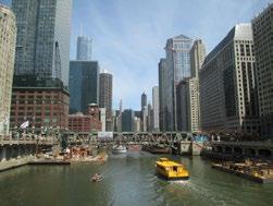
Location:
Spans the Chicago River @ LaSalle St.
Clark St. Bridge
Location:
Spans the Chicago River @ Clark St.
Bridge Type:
Double leaf trunion bascule bridge
Keynote Number: 26
Approx. Construction Date: 1928
Bridge Name: Clark St. Bridge
Historic Significance Designations:
Location Spans the Chicago River at LaSalle Street
• Orange rated on Chicago Landmarks Historic Resources Survey
Bridge Type Double leaf trunion bascule bridge
Location: Spans the Chicago River @ Clark St.
Approx. Construction Date 1928
Historic Significance Designations
Bridge Type: Bascule bridge
• Orange rated on Chicago Landmarks Historic Resources Survey
Approx. Construction Date: 1929
• Contributing element to the West Loop - LaSalle Street Historic District
Landmarks Historic Resources Survey West Loop LaSalle Street Historic District
Bridge Type: Bascule bridge
Approx. Construction Date: 1929
Location Spans the Chicago River at Clark Street
Historic Significance Designations:
Bridge Type Bascule bridge
• Orange rated on Chicago Landmarks Historic Resources Survey
Approx. Construction Date 1929
Historic Significance Designations
Orange rated on Chicago Landmarks Historic Resources Survey
Historic Significance Designations:
Keynote Number: 27
Name:
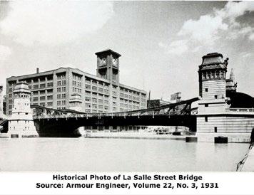
Location:
Construction Date:
Significance

• Orange rated on Chicago Landmarks Historic Resources Survey
Dearborn St. Bridge and Bridge Houses
Spans the Chicago River @ Dearborn St.
• Contributing element to the West Loop LaSalle Street Historic District LaSalle Street bridge.
Bridge Type: Bascule bridge
Approx. Construction Date: 1963
Potential Historic Significance
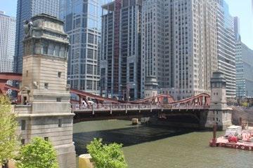

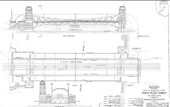
BUILDING
Keynote Number: 28
Bridge
and Bridge Houses River @ Dearborn St.
Keynote Number: 28
Bridge Name:
State St. Bridge (Bataan Corregidor Memorial Bridge)
Location Spans the Chicago River at Dearborn Street
Bridge Type Bascule bridge
Approx. Construction Date 1963
Location:
Spans the Chicago River @ State St.

Bridge Type: Trunnion Bascule bridge
Approx. Construction Date: 1949
Potential Historic Significance


State St. Bridge (Bataan
Location:
Spans the Chicago River @ State St.
Bridge Type:
Trunnion Bascule bridge
Approx. Construction Date: 1949
Location Spans the Chicago River at State Street
Bridge Type Trunnion Bascule bridge
Potential Historic Significance
Approx. Construction Date 1949


 Current photo of the Clark St. bridge
1960s photo of Dearborn St. bridge (photo from historicbridges.org)
Current photo of Dearborn St. bridge
1941 photo of the State St. bridge under construction (photo
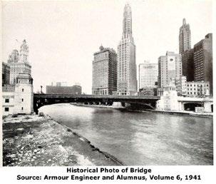
Bridge Type:
Trunnion Bascule bridge
Keynote Number: 30
Approx. Construction Date: 1930
Name: Michigan Ave. Bridge and Bridge Houses
Location: Spans the Chicago River @ Michigan Ave.
Spans
Bridge Type:
Trunnion Bascule bridge
Approx. Construction Date: 1920
Historic Significance Designations:
• Chicago Landmark (1991)
Location Spans the Chicago River at Wabash Ave.
Bridge Type Trunnion Bascule bridge
Bridge Type: Trunnion Bascule bridge
Approx. Construction Date 1930
Approx. Construction Date: 1920
Historic Significance Designations:

Potential Historic Significance Armour Engineer
• Chicago Landmark (1991)
Location Spans the Chicago River at Michigan Ave.
• Red rated on Chicago Landmarks Historic Resources Survey
Bridge Type Trunnion Bascule bridge
• Contributing to the Michigan-Wacker NR Historic District
Approx. Construction Date 1920
Historic Significance Designations
• Chicago Landmark (1991)
• Red rated on Chicago Landmarks Historic Resources Survey
• Contributing to the Michigan-Wacker NR Historic District
• Red rated on Chicago Landmarks Historic Resources Survey
• Contributing to the Michigan-Wacker NR Historic District
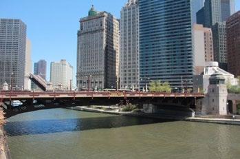
Current

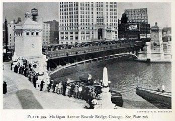


Current

Bridge Type:
Approx. Construction Date: 1937
Location Spans the Chicago River at Lake Shore Drive
Historic Significance Designations:
Bridge Type Double deck Trunnion Bascule bridge
• Orange rated on Chicago Landmarks Historic Resources Survey
Approx. Construction Date 1937
Historic Significance Designations
Orange rated on Chicago Landmarks Historic Resources Survey


Current
BUILDING/BRIDGE/MARKER
Keynote Number: 32
Name:
First Post Office Marker
Location Wacker Drive and Lake Street
Location:
Wacker Drive and Lake Street
Approx. Event Date 1833
Approx. Event Date: 1833
Historic Significance Designations
City of Chicago Marker
Historic Significance Designations:
• City of Chicago Marker

Historic Significance Designations:
• Chicago Landmark (1991)
Location 2-330 W. Wacker Drive
Approx. Event Date 1926
Historic Significance Designations
• Chicago Landmark (1991)
• Orange rated on Chicago Landmarks

Circa 1930s photo of Wacker Drive Esplanade (photo from the book Chicago’s Accomplishments and Leaders)
• Orange rated on Chicago Landmarks Historic Resources Survey and Leaders)
Location LaSalle Street & Wacker Drive
Approx. Event Date 1834
Historic Significance Designation City of Chicago Marker
Site Name
Heald Square Monument
Location
Wabash Ave. and Wacker Dr.
BUILDING/BRIDGE/MARKER INFORMATION SHEET
Approx. Event Date
1936-41
Original Architect/Artist
Lorado Taft & Leonard Crunelle
Historic Significance
• Chicago Landmark (1971)
• Red rated, Chicago Landmarks
Historic Resources Survey
• Contributing Building to the Michigan-Wacker NR Historic District and listed separately on the NR.
Current view of the Wacker Drive Esplanade

Keynote Number: 36
Site Name:
Vietnam Veterans Memorial
Location:
Wabash Ave. and Wacker Dr.
Location Wabash Avenue and Wacker Drive
Approx. Event Date:
2005
Approx. Event Date 2005
Original Architect/Artist Ross Barney & Jankowski Architects
Original Architect/Artist Ross Barney & Jankowski Architects
Keynote Number: 37
Site Name: First Movable Bridge Marker

Location: North Dearborn St. bridge house
Approx. Event Date: 1834

Location North Dearborn Street bridge house
Approx. Event Date 1834
Historic Significance Designations:
Historic Significance Designations City of Chicago Marker
• City of Chicago Marker
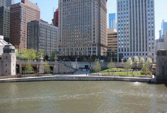


Assets Aloft LLC
17 North State Street, Suite 810
Chicago, Illinois 60602, USA
www.assetsaloft.com
Davis Brody Bond, LLP
Architects and Planners
315 Hudson Street New York, New York 10013, USA
www.davisbrody.com
Marks Barfield Architects
50 Bromells Road London SW4 0BG, United Kingdom
www.marksbarfield.com
Jacobs Engineering Group, Inc. Chicago, Illinois 60661, USA
www.jacobs.com
Economics at AECOM
71 High Holborn London WC1V 6QS, United Kingdom
www.aecom.com
Harboe Architects, PC 140 South Dearborn, Suite 205 Chicago, Illinois 60603, USA
www.harboearch.com
F10 Studios Ltd.
11 Jew Street Brighton BN1 1UT, United Kingdom
www.f10studios.co.uk
Marian Kraus Photography 2026 W. Grand Avenue
Chicago, Illinois 60606, USA
Phone (630) 222-3294
www.mariankrausphotography.com
 CLIENT CORE DESIGN TEAM CONSULTANTS
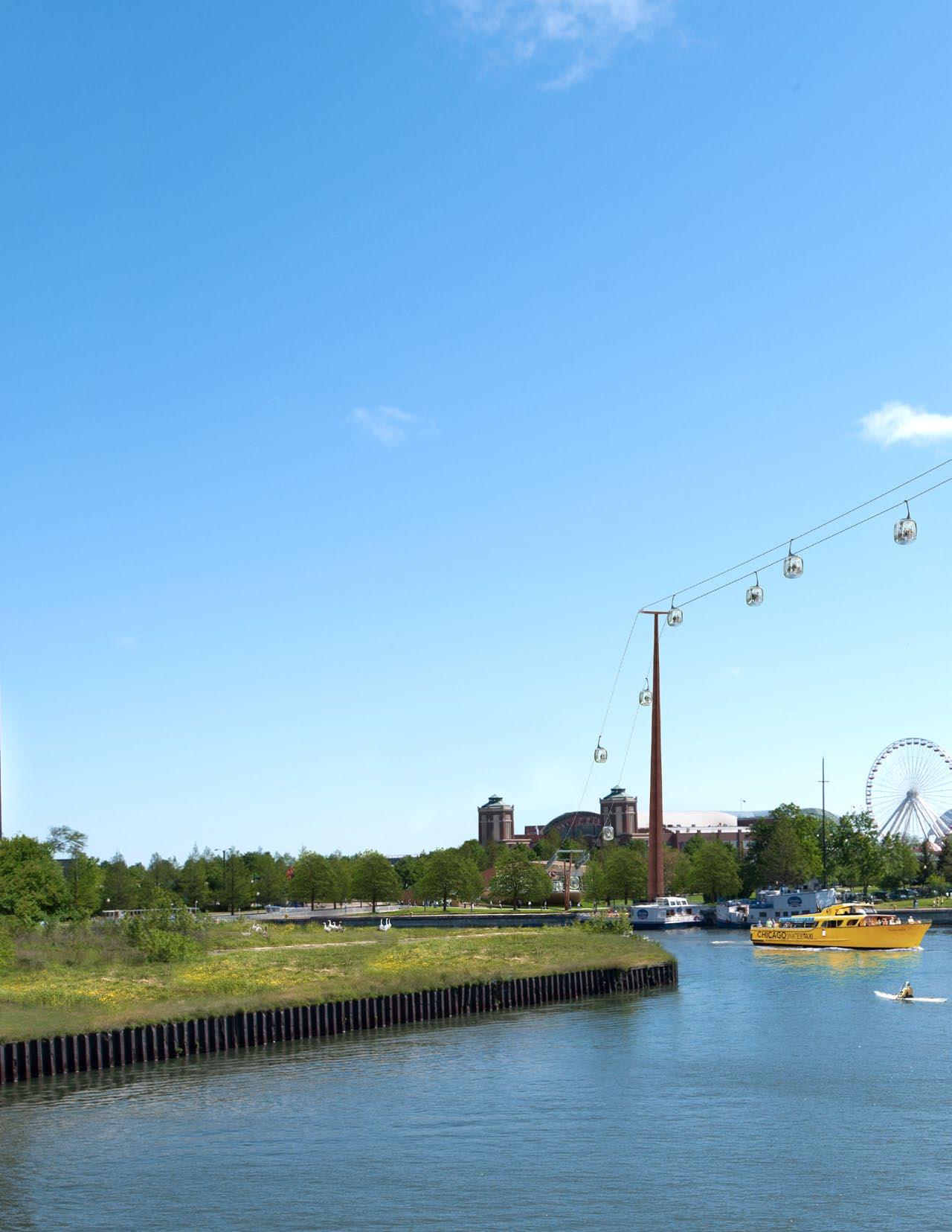
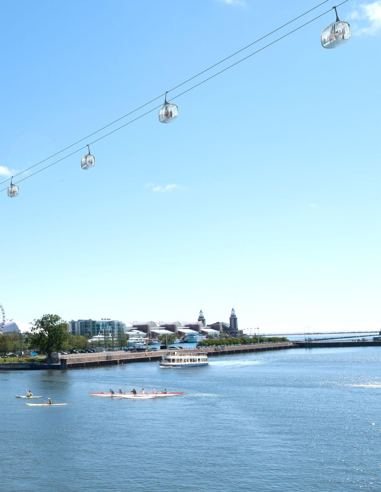 DAVIS BRODY BOND, LLP
MARKS