

BROOK UNIVERSITY PROJECT # T001873 / 15 JUNE 2015
STONY
Stony Brook University Smart Grid Innovation Center Programming Report
CLIENT
Stony Brook University
Reseach and Support Services, Suite 160 Development Drive Stony Brook, NY 11794-6010
John Fogarty
Director of Capital Planning, Campus Planning, Design and Construction
Dr. Yacov Shamash
Vice President for Economic Development and Dean of the College of Engineering & Applied Sciences
Jim Smith
Assistant Vice President for Economic Development ARCHITECT
Davis Brody Bond, LLP
Architects and Planners
One New York Plaza, Suite 4200, New York, NY 10004
Tel. (212) 633 4700 www.davisbrody.com
William Paxson, Partner-in-Charge
Tony Sieverding, Principal
Mario Samara, Project Manager
Sally Shadlun
01 Executive Summary 5 02 Context 9 • Institutional Context 9 • Project Context 15 03 Programming 25 • Project Goals & Considerations 25 • Program Process 27 • Narrative of Spaces 28 • Tabulation 45 04 Test Fit 50 • Floor Plans 56 • Sections 58 • Exterior Perspectives 60 • Options 63 05 Engineering Strategy 67 a. Sustainability 68 b. Civil Engineering 70 c. Landscape 72 d. MEP-FP Engineering 74 e. Acoustics, IT, AV & Security 76 06 Cost Estimation 83 07 Schedule 84 08 Conclusion 85 Appendices (under separate cover)
Stony Brook University Mission Statement
Site Photographic Tour
Presentations & Meeting Records
Room Data Sheets
Initial Draft Program
Dynamometer Lab Layout (Dr. Mamalis)
Cost Estimation Breakdown Contents
a.
b.
c.
d.
e.
f.
g.

4
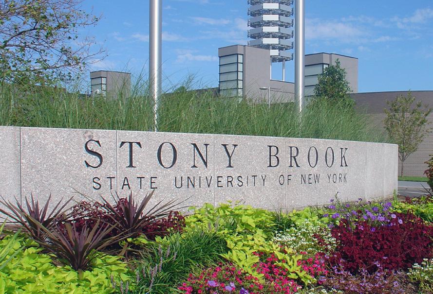
Stony Brook University Main Campus
Academic Mall Stony Brook University Main Campus
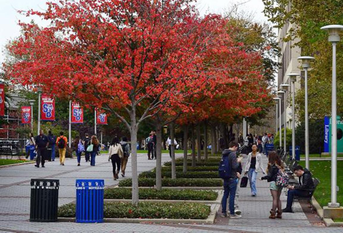
Academic Mall, Stony Brook University Main Campus
01. Executive Summary
Stony Brook University selected Davis Brody Bond Architects to develop a Program Study for the Smart Grid Innovation Center (SGIC) — an approximately 20,000 GSF addition of research laboratories, meeting and office spaces, to the Advanced Energy Center at the Research and Development Campus in Stony Brook.
The following document describes the understanding of the requested program, design assumptions and proposed solutions to meet the program requirements and University’s needs.
Overview
The University at Stony Brook got its start in 1957 at a temporary location on the Planting Fields estate in Oyster Bay, Long Island. First known as the State University College of Long Island at Oyster Bay, the college trained secondary-education teachers of mathematics and science. In 1959 construction began on the permanent campus of 480 acres donated by philanthropist Ward Melville near the village of Stony Brook. After opening in 1962, the campus became known as the State University of New York at Stony Brook, or Stony Brook University (SBU).
SBU has grown to 203 buildings on 1,454 acres (by 2014). Now with over 24,000 students, close to 2,500 faculty, and a total of 14,500 employees. It is recognized as one of the nation’s top centers for learning and scholarship. With locations at Stony Brook, Manhattan and Southampton, a Research and Development Campus, and a Hospital with an Academic Medical Center, SBU is a member of the prestigious Association of American Universities, and ranks among the top 100 U.S. universities and top 35 U.S. public universities, according to the 2010 U.S. News & World Report survey.
SBU has approximately $175.6 million in sponsored project expenditures and offers more than 40 doctoral programs. SBU, as co-manager of Brookhaven National
Laboratory (with Battelle Memorial Institute), is one of an elite group of universities — including the University of California, University of Chicago, Princeton University, and Stanford University — that run federal research and development laboratories. A driving force of the Long Island economy, SBU contributes an annual economic impact of $4.65 billion, generates nearly 60,000 jobs, and accounts for nearly 4 percent of all economic activity in Nassau and Suffolk counties, and roughly 7.5 percent of total jobs in Suffolk County.
The University has achieved what by the 1960s was intended as a goal: to become a University that would “stand with the finest in the country.”
Introduction
The Stony Brook Research and Development Campus was acquired by the University in 2005 for the purposes of creating a campus devoted to the development of technology based on basic science and engineering research. To date two of ten new buildings shown in the Master Plan developed by Beyer Blinder Belle Architects (dated August 17th, 2004), have been completed: 100,000 GSF Center of Excellence in Wireless and Information Technology (CEWIT) and 48,000 GSF Advanced Energy Center (AEC) formerly called AERTC. The current project intends to make a new Addition of approximately 20,000 GSF to the AEC building.
This new Addition is specifically designed to support research and development in Smart Grid technology — hardware and software essential to upgrade America’s electrical grid. It is expected to house offices, engineering labs, core facilities, equipment rooms, computer labs and other rooms to support this effort. The facility will bring together academic institutions, energy providers and industry research groups to develop innovative energy delivery solutions. This Addition will also be available to house start-up companies and establish corporate partners as part of the Start-Up NY program.
The new Addition is specifically designed to support R&D in Smart Grid technology — hardware and software essential to upgrade America’s electrical grid.
5
Programming
This Programming Report details the anticipated program, design assumptions and decisions made to date for the Smart Grid Innovation Center Addition to the Advanced Energy Center located on the Research and Development Campus at Stony Brook University (SBU).
The purpose of this report is to:
• Verify space, utility and operational requirements for all program functions
• Establish architectural layout, site planning and conceptual level understanding of the building’s Addition design
• Understand and address current existing AEC’s functional concerns and provide solutions through the proposed Addition
• Establish a strategy for engineered systems and processes
• Define points of connection and coordination to the campus Master Plan
• Provide a conceptual cost estimate
SBU provided an initial draft program to the Design Team (refer to Appendix E). With this document as a starting point SBU and Davis Brody Bond Architects and Planners (DBB) held programming and conceptual design meetings to better understand the requirements for the new spaces and possible layouts for the Addition.
SBU established an Advising Team to provide valuable direction and feedback to the Design Team. By way of several meetings the Advising Team worked with the Design Team to define and refine lab spaces, study adjacencies between labs and offices, and take account of the existing building’s needs in the new Addition.
Proposed Program
The Smart Grid Innovation Center Addition was initially aiming for 20,000 gross square feet (GSF), targeting 67.7% of efficiency. Through further understanding of the programmed spaces and requirements the actual program adds up to an anticipated 21,800 GSF with a targeted 65.0% efficiency, approximately 14,200 net square feet (NSF). This program is to be developed into two separate additions:
• An approximately 18,600 GSF addition which we will refer to as the Smart Grid Innovation Center (SGIC) Wing Addition, and houses the main laboratory spaces and administrative spaces.
• An approximately 3,200 GSF addition adjacent to the existing High Bay Lab which will house the Dynamometer labs.
Conceptual Design
The proposed Conceptual Design solution for the SGIC Wing Addition is developed perpendicular to the existing to minimize impact on existing spaces. It is organized similarly to the existing AEC, with an administrative component connecting with the existing administrative area (both of which will act as a whole to serve the full building), and a lab spine developed on a double loaded lab corridor on two stories. Ultimately the full building is conceived as a large access administrative area with two separate laboratory wings.
Mechanical equipment is located in a main room at grade level, with major outdoor equipment screened on the open roof of this mechanical main room. Only roof fans are intended as mayor equipment on the two story SGIC Wing Addition.
The Dynamometer Labs Addition is developed in a compact double height space volume, connected to the AEC’s High Bay labs. A second floor above the Dynamometer Test Cells will house the required electrical and mechanical equipment of this Addition.
Several options have been described in this Report to cover additional programmatic needs, and provide a better understanding on feasible expansions to the Addition. These options were taken through the cost estimation effort for comparison.
6
EXECUTIVE SUMMARY (cont’d)
Engineering Strategy
The Design Team developed an engineering strategy on several of the disciplines applicable to the project: Sustainability, Civil Engineering, Landscape, MEP-FP Engineering and Acoustic, IT Infrastructure, Audio-visual and Security. (Refer to Chapter 5).
Cost Estimation
A construction cost estimate based on the Conceptual Design proposed scheme, and proposed options has been developed. (Refer to Appendix G)
Schedule
Currently the Design Team is contracted until the completion of Schematic Design (Phase 1). Should funding become available for the completion of the design services and construction, a separate contract will cover those services (Phase 2). The following schedule provides an outline for an estimated Phase 2.
It is assumed that the building project will be complete in a single phase. If based on funding the project is to be broken down into phases the Dynamometer Labs Addition can be considered a completely separate phase. Enabling projects can be scheduled independently and may commence prior to building construction if necessary to meet anticipated milestones.
* Funding for Phase 1 ends on June 30th 2015
** Phase 2 estimate assumes award and starting with the design development phase after the 2015 summer
*** Includes Make ready / Procurement / Construction / Lab equipment installation
7 Phase 1 Start Date End Date Duration Programming Jan 2015 May 2015 4 months Conceptual Design Feb 2015 May 2015 4 months Schematic Design May 2015 June 2015* 2 months Phase 2 (est.)** Start Date (est.) End Date (est.) Duration (est.) Design Development Sep 2015 Dec 2015 4 months Estimate Review Jan 2016 Jan 2016 1 month Construction Documents Feb 2016 July 2016 6 months Construction*** Aug 2016 Sept 2018 25 months Move-in Sept 2018 Oct 2018

8
1960
Governor Nelson Rockefeller breaks ground for what would become Stony Brook University
1964
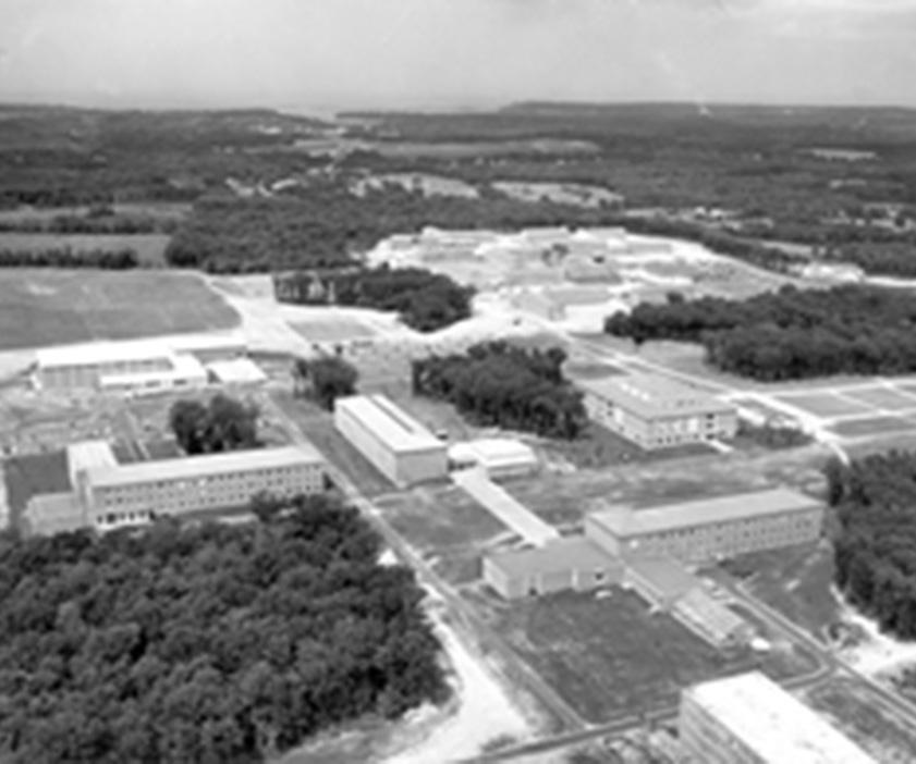
Aerial photo of Stony Brook University Campus
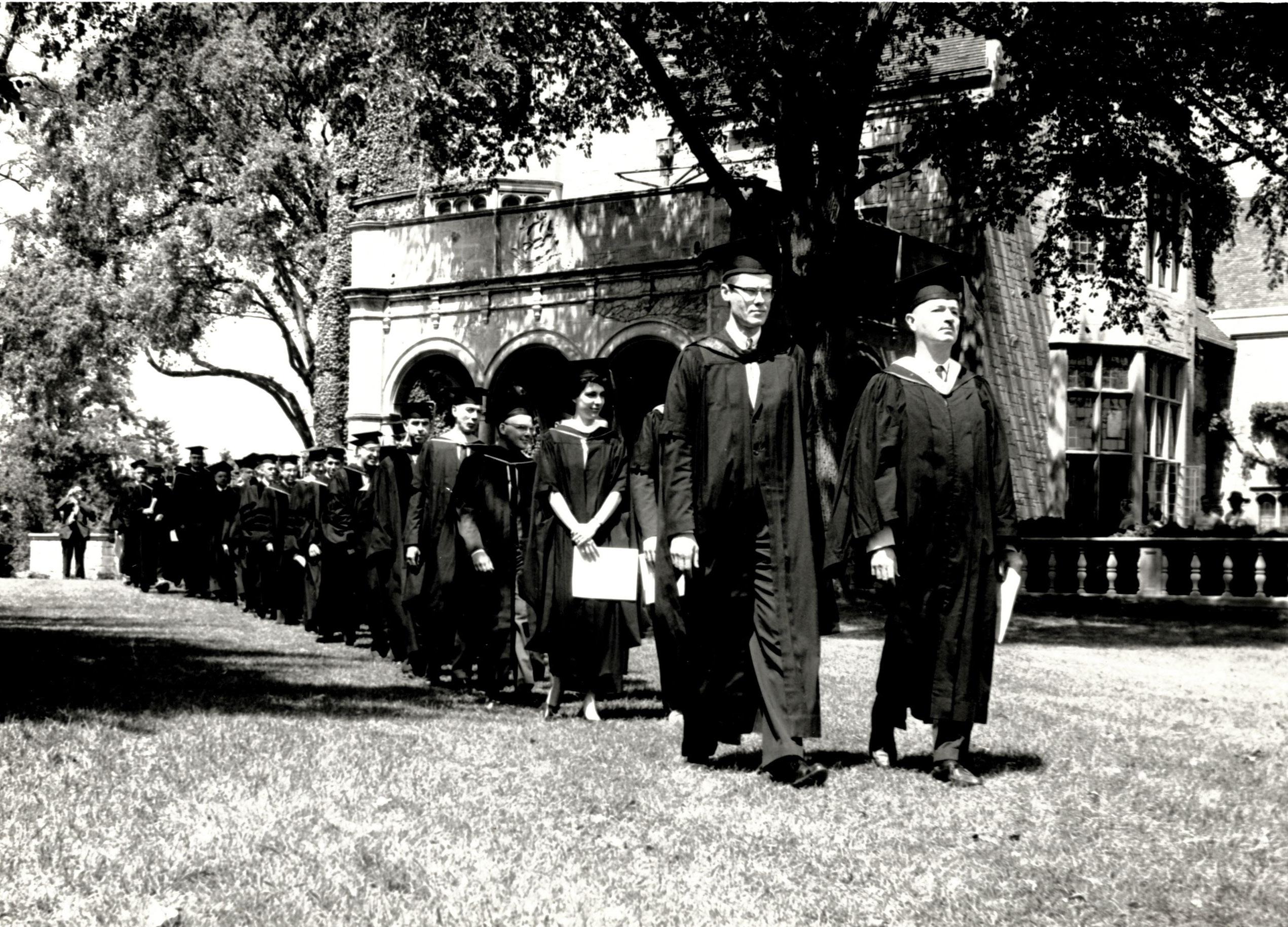
1961 First graduating class of Stony Brook University
02. Context
Institutional Context
The Institution was founded in 1957 in Oyster Bay, Long Island, as the State University College on Long Island (SUCOLI), established almost a decade after the creating of New York’s public higher education system. Initially it was envisioned as a college for the preparation of secondary school teachers of mathematics and science.
In 1962 the Institution relocated to Stony Brook and officially renamed as the State University of New York at Stony Brook, when Ward Melville, a philanthropist and businessman from the Three Village area in western Suffolk County, donated over 400 acres of land to the state for the development of a state university. By then the campus had 782 students enrolled, and in 1969 student enrollment had increased beyond the 8,000 mark.
The 1970s witnessed the growth of the University and its transformation as a major research institution in the SUNY system with strong graduate programs and scientific breakthroughs. The University lagged significantly in undergraduate education and research over undergraduate students and student life. By 1975, enrollment had reached 16,000 and expansion crossed over Nicolls Road with the construction of the Health Science Center which would be completed in 1980.
By the late 1980s the administration affirmed the need to improve other areas of the institution which included undergraduate education, student and residential life, and intercollegiate athletics. The 1990s affirmed Stony Brook University’s (SBU) success at building a research university with a strong undergraduate education.
In 1998 SBU broke into the top 100 of American research universities in the U.S. News & World Report. The same year the University and Battelle Memorial Institute were chosen by the Department of Education (DOE) as joint operators of the Brookhaven National Laboratories, joining a selective group of universities that operated national
laboratories across the nation. Enrollment reached 20,000 in 2001, and the administration’s improvement efforts climaxed with the invitation to the highly selective Association of American Universities, an organization of 62 universities across North America committed to a strong system of research and education.
In 2003, chemistry professor Paul Lauterbur received a Nobel Prize in Physiology or Medicine for his research and discovery of Nuclear Magnetic Resonance which was instrumental in the development of NMR Imaging (MRI) while at Stony Brook University. In 2005 the University bought the Flowerfield property adjacent to campus through eminent domain as land for the development of a Research and Development Campus.
In 2010 Dr. Samuel Stanley Jr., who was appointed as Stony Brook University’s fifth president a year earlier, announced Project 50 Forward, a comprehensive plan for the development of the University in the next fifty years with a focus on “operational excellence, academic greatness, and building for the future”. It is a comprehensive initiative designed to enhance the fundamental teaching, research, and service mission of SBU, while building a platform to support the future growth of the University and strengthen SBU’s role in the economic renewal of New York State.
In 2013 Stony Brook University received its best ranking ever in the National University category of U.S. News & World Report ranked as the 82nd Best University, and 34th Best Public in Undergraduate education.
Part of the State University of New York system, the University has grown tremendously and is now recognized as one of the nation’s important centers of learning and scholarship — carrying out the mandate given by the State Board of Regents in 1960 to become a university that would “stand with the finest in the country.”
The University has grown tremendously and is now recognized as one of the nation’s important centers of learning and scholarship.
9
10 N
WEST CAMPUS (MAIN CAMPUS)
EAST CAMPUS (MEDICAL CAMPUS)
SOUTH CAMPUS
RESEARCH & DEVELOPMENT CAMPUS
NY 97 (NICOLLS ROAD)
NY RTE 25A LIRR
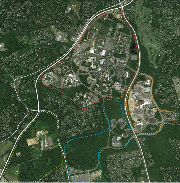
Stony Brook University, aerial photo showing campus boundaries
ADVANCED ENERGY CENTER (AEC)
STONY BROOK ROAD
LIRR - STONY BROOK STATION

Stony Brook University Campus Context
The SBU 1,040 acre campus is located in the historic north shore hamlet of Stony Brook near the geographic midpoint of Long Island, approximately 50 miles east of Manhattan and 67 miles west of Montauk. Bounded to the north by North Country Road (NY State Route 25A) the SBU campus is subdivided into four areas: “West Campus” and “East Campus” are divided by Nicolls Road (County Road 97). The Ashley Schiff Forest Preserve separates the South Campus from the West Campus. Stony Brook Road separates the South Campus from the recently acquired Research and Development Campus. The Long Island Rail Road serves the community with the Stony Brook Station situated along the northern edge of the campus.
West Campus (Main Campus)
The west campus is the center of academic life of the University. It houses major academic, athletic, and undergraduate student housing facilities while also being the original site of the University.
East Campus (Medical Campus)
It is the home to the Stony Brook University Hospital and the Health Science Center.
South Campus
It is home to the School of Dental Medicine, the School of Marine and Atmospheric Sciences (SoMAS), and the Cody Center for Autism and Developmental Disabilities.
Research and Development Campus
Located on Stony Brook Road, a mile from the center of the main campus. On November 3, 2005 the University announced it had formally acquired 246 acres of the adjacent Flowerfield property, originally owned by the St. James Gyrodyne Company of America, through eminent domain.
Stony Brook University is using this property as a Research and Development Campus, similar to other university-affiliated science parks around the country. The campus will ultimately house ten new buildings. The first building, the Center for Excellence in Wireless and Information Technology (CEWIT), was completed in October 2008 and provided 100,000 square feet of laboratory space, with the aim to “become recognized as a world leader in wireless and IT, conduct first-class interdisciplinary research in the emerging, critical technologies of the information age, address the skilled technology worker shortage, and foster new enterprise development.”
The second building, the Advanced Energy Center (AEC) (former Advanced Energy Research and Technology Center) was completed by spring 2010. A third building is underway, as well as the proposed Smart Grid Innovation Center Addition to the Advanced Energy Center.
“Stony Brook University’s unwavering commitment to excellence in research, education and discovery will make us one of the top public research universities in the world.”
Stony Brook University Strategic Vision Report
11
(cont’d)
CONTEXT
Stony Brook
Montauk
Manhattan LONG ISLAND
University Governance
The University is governed by the State University of New York (SUNY) board of trustees: a body of eighteen members which regulate all the individual units of the SUNY system, and have the authority to appoint the president of each state-operated institution. The president of Stony Brook University is the principal executive officer of the University. The position was first held by John Francis Lee and is currently held by the fifth president in the Institution’s history, Dr. Samuel Stanley Jr., serving since May 2009.
Mission and Strategic Initiatives
Stony Brook University has a five-part mission:
• To provide comprehensive undergraduate, graduate, and professional education of the highest quality
• To carry out research and intellectual endeavors of the highest international standards that advance knowledge and have immediate or long-range practical significance
• To provide leadership for economic growth, technology, and culture for neighboring communities and the wider geographic region
• To provide state-of-the-art innovative health care, while serving as a resource to a regional health care network and to the traditionally underserved
• To fulfill these objectives while celebrating diversity and positioning the University in the global community
The Advanced Energy Center’s mission: innovative energy research, education and technology deployment with a focus on efficiency, conservation, renewable energy and nanotechnology applications.

Academics
A degree from Stony Brook University, an Institution with award-winning faculty, accomplished students, rigorous and innovative academic programs, significant research opportunities, and a proven track record of successful alumni, opens doors to countless career possibilities. Stony Brook University is a large university with a small-college feel. Its Faculty is responsible for 1,990 inventions and more the 560 U.S. patents. There are 68 undergraduate majors and 80 minors and more than 100 master’s programs, 40 doctoral programs and 30 graduate certificate programs.
Student Body
In less than ten years enrollment had grown significantly from little more than 17,000 in 1996 to more than 22,000 students in 2003. Stony Brook University is expecting an increase of approximately 5,000 students (to 27,000) over the following 10 years. Given this trend the University had determined that available development sites on the existing campus had to be reserved to meet the educational and student life needs for its growing student body.
By the Fall of 2013, the University had an enrollment of 24,259 students of whom 16,107 were undergraduate students, 7,340 academic degree-seeking graduate students, and 668 first professional students. Of all students 85% are U.S. citizens or permanent residents representing all the states of the United States, and 15% are international students representing over a hundred countries around the world. In Fall 2014, the university had increased enrollment to 24,607 students of whom 16,480 were undergraduate students and 8,127 academic degreeseeking graduate students.
12
CONTEXT (cont’d)
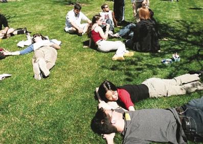
Garden at Stony Brook University
Outdoor gathering space at Stony Brook University
Rankings
In the last three years two Nobel Prizes were awarded to professors for their work conducted at Stony Brook University.
• In 2015, U.S. News & World Report ranked Stony Brook University as 88th overall among national universities.
• Ranked in the top 1% of the world’s higher education institutions by the Time Higher Education World University Rankings.
• Ranked one of the top 100 universities in the nation and one of the top 40 public universities by U.S. News & World Report and is included on their list of notable programs for undergraduate research/creative projects.
• Ranked one of the 35 best values in public colleges and universities by Kiplinger.
• One of the only 10 universities nationwide given a National Science Foundation Recognition Award for integrating research and education.
• A member of the prestigious, invitation only, Association of American Universities, Stony Brook is one of the 62 leading research institutions in North America and the co-manager of Brookhaven National Laboratory.
Stony Brook University has established itself as one of America’s most dynamic public universities, a center for academic excellence and an essential part of the region’s economy.
Stony Brook University’s main campus on Long Island’s North Shore encompasses not only the main academic areas of the University, but also Stony Brook Medicine, which includes the five health science schools, Stony Brook University Hospital, Stony Brook Long Island Children’s Hospital, the Long Island State Veterans Home and major healthcare centers, programs and clinics.
The University’s need for growth extends beyond its commitment to its students given its status as leading research institution and the engine driving the Long Island economy. Being invited to join the Association of American Universities proves that the University has reached the top echelon of American universities. In addition to medical and dental science discoveries, Stony Brook University also undertakes major research initiatives such that it ranks as one of the top public universities in terms of federal and corporate grant research funding.
Multiple regional economic benefits result from Stony Brook University, in academics, research, health care, cultural and economic development. For the Long Island Region (Nassau and Suffolk Counties) the University is the third largest employer, the largest single-site employer and the primary economic engine of the Long Island economy.
13
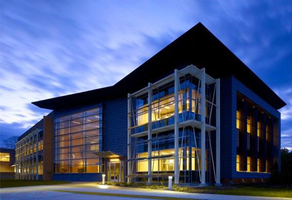
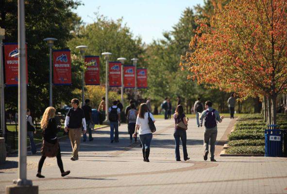
Advanced Energy Center, SBU Research & Development Campus Academic Mall, Stony Brook University Main Campus
Ten New Buildings proposed per BBB Master Plan
B1 Center For Excellence In Wireless And Information Technology (CEWIT)
B2 Nanoscience and Technology, per Master Plan (Current Advanced Energy Center (AEC))
B3 Computational Neuroscience Center For Biotechnology
B4 R&D Partners Research Center
B5 Development Facility
B6 Software Incubator Facility
B7 High Tech Competitiveness Institute
B8 Site 1 R&D Facility
B9 Site 2 R&D Facility
B10 Site 3 R&D Facility
 Research & Development Campus: 2017 (from Beyer Blinder Belle Master Plan)
N
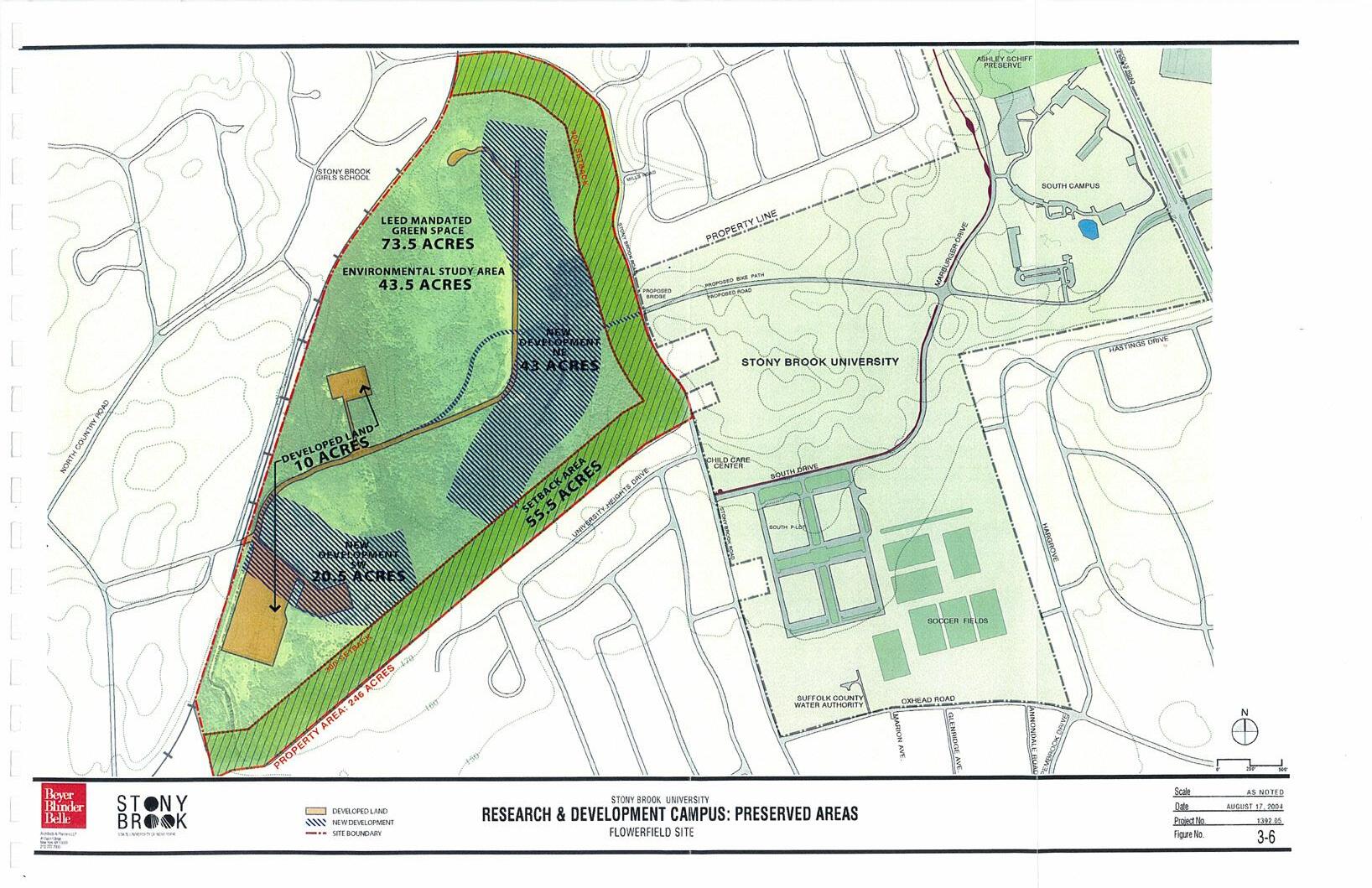
Research & Development Campus: Preserved Areas (from Beyer Blinder Belle Master Plan)
Research and Development Campus — Master Plan
In order to advance its academic and research missions and to support the economic development of Long Island, Stony Brook University announced in 2005 the acquisition of a parcel of approximately 246 acres on the west side of Stony Brook Road from the Gyrodyne Company of America, and developed it as Stony Brook University Research and Development Campus which is planned to hold 10 new research and development buildings.
A Master Plan was prepared in 2004 for this campus by Beyer Blinder Belle Architects. The Master Plan was seeking to provide an efficient and attractive use of the project site, maintaining its topography and plantings, respecting the site community character as a largely undeveloped parcel. An internal road which follows the shape of the property, organizes the buildings and parking areas.
The Master Plan exhibits the University’s intention to interweave the project site with a network of bikeways and pedestrian trails, and to open the site for the educational and recreational use and benefit of the local and University communities. In addition, across the project site, the Master Plan allows for the use of certain areas identified by the University as being of interest for environmental, ecological, botanical and geological research purposes. The Master Plan will allow the University to fulfill its mandate to undertake building and site design in compliance with the Leadership in Energy and Environmental Design (LEED) recommendations.
The LEED guidelines recommend the conservation of green space in a one-to-one basis with developed property, which in the Master Plan accounts for 73.5 acres of developed or disturbed property. Even though the University is a zoning-exempt institution, it is planned to meet this criterion and the Master Plan is projected to provide approximately 73.5 acres of open land at its anticipated completion in 2017.
The University established zones of “no building construction” along Stony Brook Road and University Heights Drive of 300 feet, which is well outside the proposed boundary limit for the Smart Grid Innovation Center Addition. This forested non constructed area creates approximately 55.5 acres of permanent buffers on the project site. CONTEXT
15
(cont’d)
Stony Brook University Main Campus
Academic Mall, Stony Brook University Main Campus
LongIslandRail Road
CEWIT AEC Recharge Basin
Stony Brook Road
PropertyArea-246ACRES
300’Setback
SetbackArea-55.5ACRES
DevelopmentDrive
Previously Developed Land (as of 2004)
2004 BBB Master Plan Proposed Buildings
Existing Buildings (as of 2015)
Proposed SGIC Addition
16
N
To date two of the ten projected buildings have been constructed: the Center of Excellence in Wireless Information Technology (CEWIT) and the Advanced Energy Center (AEC); with the Smart Grid Innovation Center Addition and the Innovation and Discovery Center in their initial design stages. The Innovation and Discovery Center will be located south of Development Road and is intended as a “mezzanine” facility to promote the expansion of start-up and incubator businesses currently housed on campus, and to allow for the relocation of other innovative new companies.
The Master Plan process was based on multiple influences, both physical and political, and to date has included numerous parties from the University, community, and consultants. Implementation of some aspects of the Master Plan may prove challenging due to funding mechanisms only allowing the development of one project at a time.
It was initially planned that by 2017 the Research and Development Campus would contain approximately 830,000 GSF of new research space, and would be connected to the West Campus by a connection at Stony Brook Road. Construction of the Proposed Action was conservatively assumed to be created over 10 years following completion of the CEWIT building.
Recognizing and providing for the dynamic and everevolving nature of emerging technologies, the University plans to populate its Research and Development Campus with a series of buildings that will not only capitalize on emergent intellectual and industrial trends, but also allow for maximum flexibility, should future research trends dictate growth in other directions.
To foster collaborative research and the economic development envisioned for the Research and Development Campus, a portion of the buildings’ spaces could be occupied by private businesses teamed with the University in corporate research and product development activities.
The Advanced Energy Center did not follow the exact location and orientation per the proposed Master Plan due to two factors:
• It had to be moved approximately 80’ north due to the already existing Recharge Basin, which prevented the initial building location
• It was decided through its design phase that the building would be developed in a West-East orientation, perpendicular to originally proposed by the Master Plan to allow for solar and energy advantages.
The proposed SGIC Addition will develop perpendicular to the existing AEC matching the original building orientation depicted in the Master Plan. Due to the actual AEC location further north than originally planed, future buildings to the north of this site may move further north and will be able to develop within the developed area boundary, clear from the 300’ no building construction set-back.
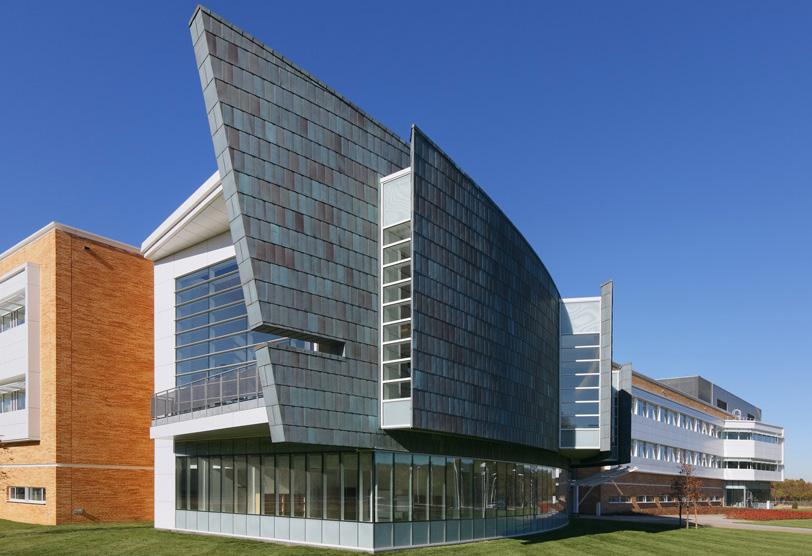
17
CONTEXT (cont’d)
Advanced Energy Center (AEC)
Center of Excellence in Wireless Information Technology (CEWIT)
Vehicular Access and Parking
Many of the building’s regular users will arrive through private vehicles to the parking lots coming from the east from the main campus or from the main access road (route NY-347). Students, faculty and other building users will arrive primarily this way, and thus additional parking spots are provided in the proposed parking for the SGIC The proposed parking will also address the deficiency in parking at peak times at the existing AEC. Parking layout matches the existing, developing at the east end of the road, north of the existing parking lot, and clear from the 300’ set-back from Stony Brook Road.
The loading dock of the existing building remains as the main delivery area, though access through the north end of the new facility is proposed for vehicular traffic to load and unload.


18
VEHICULAR ACCESS PARKING AREAS N Nicolls Road Nicolls Road NorthCountryRoad Stony Brook Road SouthDrive Marburger Drive CircleRoad RESEARCH & DEVELOPMENT CAMPUS SOUTH CAMPUS EAST CAMPUS WEST CAMPUS to NY-347 to NY-347 CONTEXT (cont’d) AEC & SGIC Addition 0 500’ 1500’ 3000’
Public Transportation / Bus & Train Access
Public transportation to the area is provided by the Long Island Rail Road North East line (Penn Station to Port Jefferson) at the Stony Brook Station, 1.5 miles from the AEC building location.
Bus service from Stony Brook University connects the train station to the main campus and the other campus areas, having 6 bus lines, with buses running of every 15 minutes. A bus stop is within 200’ of the AEC main entrance.


19
LONG ISLAND RAIL ROAD STONY BROOK STATION - LIRR N
RESEARCH & DEVELOPMENT CAMPUS SOUTH CAMPUS EAST CAMPUS WEST CAMPUS RAIL ROAD BUS ROUTE R&D PARK BUS SHUTTLE LIRR TO NYC AEC & SGIC Addition 0 500’ 1500’ 3000’
LIRRTOPORTJEFFERSON
Pedestrian and Bicycle Access
The main pedestrian paths are within the Main Campus. The Research and Development Campus being approximately 1.5 miles from the Main Campus is not adequately accessible by pedestrian traffic.
Stony Brook University encourages bike use, and provides a bike share system to students, faculty, staff and visitors (Wolf Ride Bike Share). Currently the closest station is within 0.7 miles at the South Parking lot, in the South Campus. Bike racks are provided in the Advanced Energy Center for bike users.


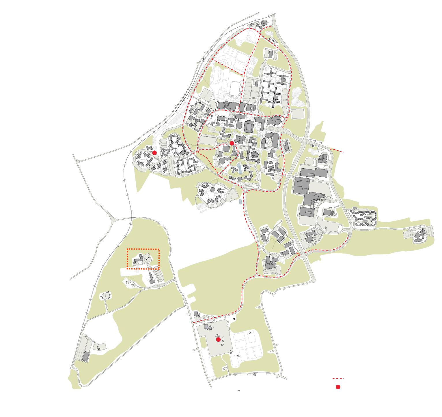

20
BIKE PATHS WOLF BIKE SHARE LOCATIONS Stony Brook Road SouthDrive Marburger Drive CircleRoad RESEARCH & DEVELOPMENT CAMPUS SOUTH CAMPUS EAST CAMPUS WEST CAMPUS
N AEC & SGIC Addition 0 500’ 1500’ 3000’
CONTEXT (cont’d)

The proposed additional parking to serve the needs of the building addition develops north of the existing parking lot, keeping all parking areas east of Innovation Road. The bus stop that links to the Main Campus, and from there to the Stony Brook train station, is within 200 feet of the Advanced Energy Center’s main access. The current bike racks at the Advanced Energy Center would be relocated and possibly expanded to meet the needs of the increased attendance to the additional facility.
21 N WOODED AREA
25’ 0’ 75’ 150’ PROPOSED PARKING EXISTING PARKING VEHICULAR ACCESS R&D PARK SHUTTLE R&D PARK SHUTTLE STOP AEC/SGIC BIKE RACK AEC PROPOSED SGIC WING PROPOSED DYNAMOMETER LABS Main Access RECHARGE BASIN Innovation Road
22 18. Director’s Suite 19. Multi-User Research Facility 20. Loading Dock 21. Recycling Area 22. Advanced Transportation Lab 1 2 3 4 5 6 7 8 9 10 11 18 19 19 19 19 20 21 22 12 13 14 15 16 16 16 17 First Floor Labratory Area Administrative Area 1. Executive O ce 2. Open O ce 3. Main Access 4. Lobby/ Gallery 5. Conference Room 6. Energy Harvesting and Mechatronics Lab 7. Energy Incubator Tenant 8. IT Room 9. Scanning Electron Microscope 10. Transmission Electron Microscope 11. Microscopy Prep Area 12. Atomatic Force Microscope 13. Ultraviolet Visable Spectroscopy Lab 14. Xray Scanning Center 15. Confocal Microscope 16. Battery Storage 17. Building Automation Systems Room 18. Director’s Suite 19. Multi-User Research Facility 20. Loading Dock 21. Recycling Area 22. Advanced Transportation Lab 6 7 8 9 10 11 18 19 19 19 19 20 21 22 12 13 14 15 16 16 16 17 Labratory Area 1. Conference Room 2. Open O ce 3. Break Room 4. Library/Lounge 5. Share Equipment Lab 6. Energy Incubator Tenant 7. IT Room 8. Smart Grid Lab 9. Smart Grid Cybersecurity Lab 10. Battery Storage 11. Laser Solar Photovoltaic Lab 12. Chemical Storage 13. Glass Washer/Deionized Water 14. Outdoor Solar Lab 15. Advanced Transporation Lab 1. Conference Room 2. Open O ce 3. Break Room 4. Library/Lounge 5. Share Equipment Lab 6. Energy Incubator Tenant 7. IT Room 8. Smart Grid Lab 9. Smart Grid Cybersecurity Lab 10. Battery Storage 11. Laser Solar Photovoltaic Lab 12. Chemical Storage 13. Glass Washer/Deionized Water 14. Outdoor Solar Lab 15. Advanced Transporation Lab 1 2 3 4 5 6 6 6 6 7 8 9 10 10 11 12 13 14 15 Second Floor Labratory Area Administrative Area N Advanced Energy Center First Floor Plan Advanced Energy Center Second Floor Plan Main Access 1. Executive O ce 2. Open O ce 3. Main Access 4. Lobby/ Gallery 5. Conference Room 6. Energy Harvesting and Mechatronics Lab 7. Energy Incubator Tenant 8. IT Room 9. Scanning Electron Microscope 10. Transmission Electron Microscope 11. Microscopy Prep Area 12. Atomatic Force Microscope 13. Ultraviolet Visable Spectroscopy Lab 14. Xray Scanning Center 15. Confocal Microscope 16. Battery Storage 17. Building Automation Systems Room 18. Director’s Suite 19. Multi-User Research Facility 20. Loading Dock 21. Recycling Area 22. Advanced Transportation Lab 9 10 11 19 20 21 22 12 13 14 15 16 16 16 17 Labratory Area 1. Conference Room 2. Open O ce 3. Break Room 4. Library/Lounge 5. Share Equipment Lab 6. Energy Incubator Tenant 7. IT Room 8. Smart Grid Lab 9. Smart Grid Cybersecurity Lab 10. Battery Storage 11. Laser Solar Photovoltaic Lab 12. Chemical Storage 13. Glass Washer/Deionized Water 14. Outdoor Solar Lab 15. Advanced Transporation Lab 6 Labratory Area
Project Context — Advanced Energy Center (AEC)
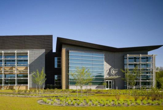
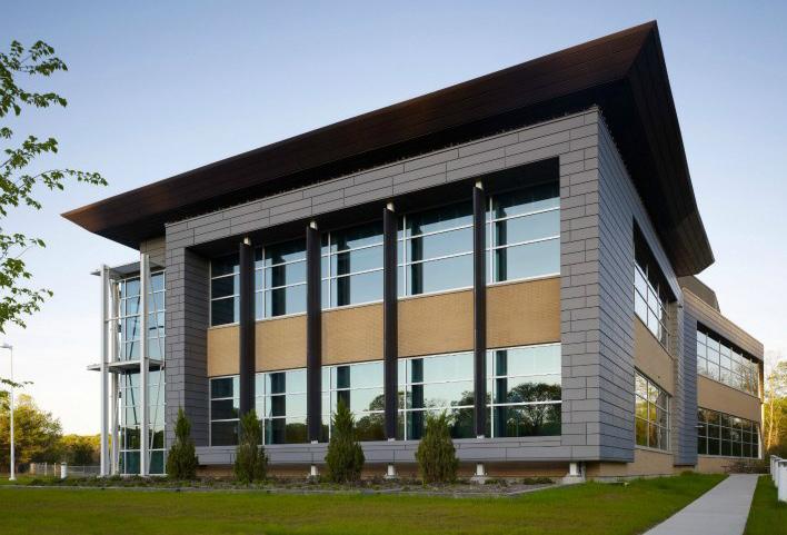
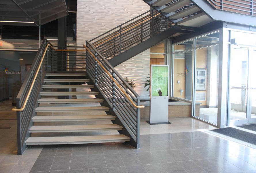
The Advanced Energy Center (formerly AERTC) is at the forefront of energy research and technology. The Center partners with other universities and research institutions, energy providers, private industry, and our national Department of Energy to develop advanced, cuttingedge technologies that explore ways of producing and promoting clean energy. Consistent with that mission, the focus and construction of the facility incorporates multiple energy-sustainable design principles.
The AEC, New York’s first LEED Platinum research facility, is organized around core and flexible laboratories which support the main energy research thrusts known today. Flexible labs allow for diversity of research and are easy to convert in the future. Specifically designed to meet everchanging research needs and agendas, the AEC provides space for the university and its research partners far into the future. The AEC’s traditional labs, the high-bay lab, and the outdoor spaces support research at different stages from nano-scale to pilot plant to real life simulation; all in an energy-forward building. From site selection to stormwater runoff control, building construction management and the materials used, to water usage reduction and energy efficient lighting, the AEC promotes energy efficiency at its maximum.
The Advanced Energy Center is an energy-focused facility that has extensive research laboratories, user-facilities and start-up incubator labs. In addition to the leading facilities, the AEC has formal programs for energy-business assistance, technology advisement and support.
As New York State’s designated Center of Excellence in Energy, the Center facilitates cross collaboration of researchers, industry and energy subject-matter experts throughout the state. This collaboration culminates the annual Advanced Energy Conference attracting 2000+ attendees with 500+ public and private companies participating and 40 colleges and universities engaged.
The Center has attracted well over $140M in funding and has affiliations with three U.S. Department of Energy EFRC’s (Energy Frontier Research Centers), which together account for roughly $50M in federal funding to New York State. The Center is the research base for the Department of Energy’s $25M Smart Energy Corridor project.
The Advanced Energy Center currently supports 121 energy projects and eight major research and training centers. Each of these centers engages an expert team researchers, educators and investigators dedicated to pursuing advanced energy solutions. As a founding organization of the New York State Smart Grid Consortium (NYSSGC), the AEC also works closely with the NYSSGC in bringing together business and government leaders, policy-makers and researchers in developing innovative programs to deploy smart grid technology.
As a result of this succesful model which integrates both research labs and incubator tenant spaces, additional program space was required and developed into the proposed Smart Grid Innovation Center Addition project. This current spatial model is replicated in the proposed SGIC Wing Addition.
23 CONTEXT (cont’d)
Advanced Energy Center, SBU Research & Development Campus
Advanced Energy Center, interior lobby
Site Strategy
Overview
The Smart Grid Innovation Center Wing Addition to the Advanced Energy Center needs to be connected to the existing lobby. Given that the existing AEC lab wing develops west of the existing lobby, the main access to the building is on the South façade and the administrative spaces open to the east, the most convenient and least disruptive location for the new SGIC Wing Addition is the north end of the existing lobby area.
The SGIC Wing develops perpendicularly to the existing building, giving the SGIC presence on Innovation Road from the main access to the AEC building, and providing a visual connection to the future buildings planned to be constructed north of the site. The orientation prevents the blocking of daylight or views from the existing building, as well as opening the complex to an outdoor green space behind the building, to be used (weather permitting) as a relaxing spill space for building users and events held at the Main Conference Room.
The Dynamometer Lab Addition will be located next to the existing High Bay Lab due to the similarity of program developed in these spaces, while providing a physical sound buffer to the rest of the lab spaces in the building from the inherently noisy aspect of the Dynamometer Labs. The west location next to the High Bay Lab is driven by the physical connection to this space, and the inability to attach to the other two open facades (east and south).
Site Strategy Objectives
• Create an efficient and attractive use of the site and its relation to the existing building and additions
• Maintain site’s topography and plantings, respecting the site community character as a largely undeveloped parcel
• Provide suitable vehicular spaces for students, staff and tenant users from the Start-Up NY programs to be coordinated with parking based on the Research and Development Campus Master Plan layout
Zoning
No zoning regulations apply.
Site Location and Campus Context
The Smart Grid Innovation Center Addition will redefine the current north edge of the Research and Development Campus. Travel from the Main Campus, a mile distant, will be by private car, campus shuttle bus or bicycle. Car parking includes electrical recharge stations, and provides preference parking for carpools.
Bike paths across the campus connect all the main campus areas, and do extend shyly to the Research and Development Campus. A bike path in itself is not currently servicing this area, and the closest bike rental program station is 0.7 miles away. Bike racks are provided at the AEC to satisfy the current bike traffic.
Much of the area’s social interactions currently occur indoors, in the main common areas. The proposed orientation of the SGIC Wing opens up to the adjacent landscape, proposing an outdoor terrace for the building users to profit from, and expanding on the current outdoor seating area of the existing building. The proposed SGIC Wing will be visible from Innovation Road as you access the AEC building and it will develop the program into two main distinct volumes (administrative space and lab space).
This orientation also matches the initial intent orientation depicted in the Master Plan for this area, and will give a visual tie to the future research buildings to be built north of the existing. The placement of the building addition balances several factors: a desire to retain the open space and views from the existing AEC, proximity of use and connectivity to the existing program, and developing an efficient footprint which develops into a functional program. Clearance around the constructed structures provide fire truck access in case of emergency.
Topography
The project site is fairly flat, north to south and east to west. The north end is a wooded area which will need to be cleared to accommodate for the new SGIC wing. Landscape provisions account for an integration of these treated spaces with the existing landscape and provide enough open clearances for use and visual pleasure. There are no drastic changes in elevation in the area.
24
CONTEXT (cont’d)
03. Programming
Early in 2015 Stony Brook University selected Davis Brody Bond Architects and Planners as the architect for the Phase 1 (Programming and Schematic Design) of the Smart Grid Innovation Center Addition to the Advanced Energy Center. Phase 2, comprising of Design Development, Construction Documentation and Construction Administration will not be awarded until the funds become available.
Programming efforts involved preparing a detailed program for the Smart Grid Innovation Center Addition, and testing that program by developing conceptual plans for each floor that incorporates the proposed program. This report describes the findings of this part of the project work. The programming exercise uses the initial program provided by Stony Brook University (refer to Appendix E) as a basis to develop a specific program that defines each space, its function, size and adjacency requirements. Development of program requirements involve a series of meetings with user groups, as well as regular reviews with select representatives of the University (SBU Advising Team).
Project Goals & Considerations
Programming studies typically establish space requirements for group users independently of other considerations, with the resulting document forming a basis for further development of a building’s layout and design. Goals for the Smart Grid Innovation Center Addition involve program priorities, system performance targets and solving current issues.
Key project goals are identified below:
• SGIC Addition is to read as part of the existing building. It shall pattern its high-tech look, using the same architectural language to provide a cohesive building
• Maximize floor area for program space
• Provide high quality sciences laboratory facilities
• Circulation patterns to allow for functional flow between new programmed spaces and existing
• Maintain existing office views
• Minimize disruption to academic activities and building operations
• Design a fully ADA compliant facility
• Target LEED Silver certification under the new LEED v4
The understanding of the Advanced Energy Center‘s current concerns also helped develop the road map for the proposed Addition.
Stony Brook University has identified the main concerns as follows:
• Elevator. The current elevator location and size prevents proper loading at the existing building. Its location does not encourage passenger use, being far away from the lobby. The current elevator situation has been considered by the building users as the number one problem in the existing facility. The proposed elevator will be close to the existing lobby and will provide enough capacity and size to use as service elevator for both buildings.
• Laboratories / Future flexibility. The proposed lab spaces will provide the infrastructure for several lab services (fume hoods, point exhausts, electrical, data, lab gas) to be able to address future equipment additions. It has been planned that the assigned labs which require fume hoods be located at the 1st floor to provide the infrastructure and systems for these, allowing for future minimal invasion if fume hoods need to be added to the 2nd floor.
• Toilets. The current number of toilet stalls is inadequate for the number of men using the building. At peak times lines are formed at the men’s toilets. New toilet stalls will be provided in the addition to mitigate this issue.
• Parking. The current parking is full at AEC’s peak times, and parking occupies even non-parking dessignated areas. The proposed parking for the Addition will have enough parking spots to address this issue.
• Loading dock. The current loading dock is planned to absorb the added loading traffic due to the Addition, but its location is not ideal to serve the added program. Paved access into the Addition from Innovation Road will be provided to wheel in equipment.
• Existing lab flooring scratches and stains. A more durable vinyl lab flooring is proposed for the Addition.
25
Programming
This Programming Report defines the anticipated program, design assumptions and decisions made to date for the Smart Grid Innovation Center Addition to the Advanced Energy Center located on the Research and Development Campus at Stony Brook University.
The purpose of this report is to:
• Verify space, utility and operational requirements for all program functions
• Establish architectural layout, site planning and conceptual level understanding of the building addition design
• Understand and address current existing AEC functional concerns and provide solutions through the proposed addition
• Establish the strategy for all engineered systems and processes
• Define coordination to the campus Master Plan
• Provide a conceptual cost estimate
The AEC has been forging partnerships between universities, industry and national laboratories since its opening back in 2010, to develop reliable, economical and plentiful sources of energy. The center has been promoting clean and economical energy strategies through research, technical applications and community outreach. The Smart Grid Innovation Center Addition to the AEC will continue to promote and develop these efforts.
The added facility will include a mix of Energy Research Labs and Incubator Tenant spaces of various sizes. Two Dynamometer test cells will be added adjacent to the existing High Bay Lab in the AEC building.
Energy Research Labs will hold:
• Advanced Energy Storage
• Smart Grid — Test & Validation
• Smart Grid —Modeling & Simulation
• Process Engineering
• Distribution Power Engineering
• General — one lab module will hold a flexible generic lab till it is assigned to a specific researcher
Smart Grid
“Smart grid” generally refers to computer based automated and remote control components deployed to modernize existing power delivery systems. These systems are made possible by two-way communication technology and computer processing that has been used for decades in other industries. Smart grids are beginning to be used on electricity networks, from the power plants and wind farms all the way to the consumers of electricity in homes and businesses. They offer many benefits to utilities and consumers, mostly seen in big improvements in energy efficiency on the electricity grid and in the energy users’ homes and offices.
For a century, utility companies have had to send workers out to gather much of the data needed to provide electricity. The workers read meters, look for broken equipment and measure voltage, for example. Most of the devices utilities use to deliver electricity have yet to be automated and computerized. Now, many options and products are being made available to the electricity industry to modernize it.
The “grid” amounts to the networks that carry electricity from the plants where it is generated to consumers. The grid includes wires, substations, transformers, switches and much more.
Much in the way that a “smart phone” means a phone with a computer in it, smart grid means “computerizing” the electric utility grid. It includes adding two-way digital communication technology to devices associated with the grid. Each device on the network can be given sensors to gather data (power meters, voltage sensors, fault detectors, etc.), plus two-way digital communication between the device in the field and the utility’s network operations center. A key feature of the smart grid is automation technology that lets the utility adjust and control each individual device or millions of devices from a central location.
The number of applications that can be used on the smart grid once the data communications technology is deployed is growing as fast as inventive companies can create and produce them. Benefits include enhanced cyber-security, handling sources of electricity like wind and solar power and even integrating electric vehicles onto the grid.
26
PROGRAMMING (cont’d)
Advising Team and Building Users
During this programming phase work sessions were held with the SBU Advising Team to understand and develop the needs of the different program spaces in this facility, as well as the administrative space needs. This multidiscipline committee is as follows:
Dr. Yacov Shamash Vice President for Economic Development and Dean of the College of Engineering & Applied Sciences Stony Brook University (through J. Smith)
John Fogarty Director of Capital Planning
Jim Smith Assistant Vice President of Economic Development
Robert Slavonik Facilities Manager
User meetings were held with the following Faculty members to better understand the individual science to be done in the new spaces in the new facility:
Dr. Esther Takeuchi & Dr. Amy Marschilok Advanced Energy Storage Lab
Dr. Sotirios Mamalis & Dr. Benjamin Lawler Dynamometer Labs
Dr. Devinder Mahajan Process Engineering Lab
Rich Jensen Facilities Manager
Jim Smith was the contact person to account for all the other administrative and office spaces and general labs and incubator labs. His direction was key into understanding the current existing building situations which could be resolved by the Addition.
Program Process
An initial program scope was submitted to the Design Team to address the additional spaces to the AEC (refer to Appendix E). With this document as a starting point programming and conceptual design meetings were held to better understand the requirements for the new spaces and possible layouts for the new Addition.
The Advising Team worked with the Design Team at a kick-off meeting and over three subsequent conceptual layout and programming sessions. During these sessions lab spaces were defined and refined, adjacencies between labs and offices were understood, and existing building’s needs were accounted for.
In April 2015 DBB began conducting programming interviews with users and Facilities personnel and SBU representatives. This data was used as a verification of the initial starting point for the programming effort. The goal of the programming interviews was to understand the qualitative and quantitative needs of each specific group. With information collected at these interviews DBB created specific room data sheets (refer to Appendix D) for each of the spaces to establish space requirements, room types and sizes, relationships, and adjacencies. Meeting records from the programming interviews have been compiled in this report (refer to Appendix C).
SBU Review
Throughout the development of the Program and Conceptual Design layouts representatives from Stony Brook University have provided valuable direction and feedback. Integral to the development of the project has been the review and revision of the Room Data Sheets advanced by DBB.
27
Program Spaces
In initial meetings, the Advising Team and Davis Brody Bond determined the Addition will house the following program:
Laboratory Spaces
• 4 Incubator tenant labs of various sizes and intermixed with the Energy Research labs
• 8 Energy Research labs, including:
- Smart Grid labs
- Advanced Energy Storage lab
- Process Engineering lab
- Distribution Power Engineering lab
- 2 Dynamometer labs
Administrative Spaces
• Main Conference Room for board meetings
• Small Conference Room (8–10 people)
• Student Workstation Room
• Student Poster Display Area
• Faculty offices and cubicles
- 8 private faculty offices
- 6 support cubicles
• Office Storage
28
INCUBATOR TENANTS Incubator Tenanat #4 800 SF Incubator Tenant #3 600 SF Incubator Tenant #2 600 SF Incubator Tenant #1 400 SF Advanced Energy Storage Dr. Takeuchi Lab #1 900 SF Dynamometer Cell & Control #1 Dr. Mamalis 828 SF Smart Grid Test & Validation EE Lab #2 900 SF Smart Grid Modeling/Simulation CSE/AMS Lab #3 600 SF Process Engineering Dr. Mahajan Lab #4 900 SF Distribution Power Engineering TBD Lab #5 900 SF General TBD Lab #6 900 SF Dynamometer Cell & Control #2 Dr. Mamalis 828 SF Cubicle #1 100 SF Main Conference Room 1400 SF Small Conf. Room 200 SF Student Workspace/ Library 600 SF Display Area 400 SF O ce Storage 360 SF ENERGY RESEARCH LABS OFFICES & CUBICLES MEETING & MISCELLANEOUS Smart Grid Innovation Center DRAFT PROGRAM DYNAMOMETER LABS Cubicle #2 100 SF Cubicle #3 100 SF Cubicle #4 100 SF Cubicle #5 100 SF Cubicle #6 100 SF 14 January 2015 O ce #1 100 SF O ce #2 100 SF O ce #3 100 SF O ce #4 100 SF O ce #5 100 SF O ce #6 100 SF O ce #7 100 SF O ce #8 100 SF Laboratory Program Energy Research Labs 5,100 sf Incubator Tenants 2,400 sf Dynamometer Labs 1,656 sf Total Laboratory Program (NET) 9,156 sf (67.7% of total Program) Administrative Program Offices & Cubicles 1,400 sf Meeting & Miscellaneous 2,960 sf Total Administrative Program (NET) 4,360 sf (32.3% of total Program) Total NET program (Lab & Admin) 13,516 sf Anticipated GSF 20,000 sf (67.6% efficiency) Initial Program as of January 14th, 2015
(cont’d)
PROGRAMMING
Through additional meetings and further understanding of the program needs the actual anticipated program values varied slightly, which would ultimately have an impact on the anticipated gross square feet (GSF) for the building addition and therefore to the actual addition’s construction targeted efficiency. Specific items which contributed to this variation from the initial program are as follows:
Laboratory Spaces
• The need for a second floor on the Dynamometer Lab cells for electrical equipment increased the initial GSF for this area, although this space is not accounted for in the Net square footage.
• In addition to this, storage space for the Dynamometer Labs was requested.
Administrative Spaces
• A separate 250 SF Food Service Room which is also used as a Staff Break Room, in lieu of the initial thought of the Small Conference Room to cope with these functions.
• Faculty Offices (initially 100SF) to match the existing SBU Standards faculty office size (120SF).
(*) includes 200sf of Storage
(**) anticipated GSF has been adjusted proportionally to account for the additional program
29 INCUBATOR TENANTS Incubator Tenanat #4 800 SF Incubator Tenant #3 600 SF Incubator Tenant #2 600 SF Incubator Tenant #1 400 SF Advanced Energy Storage Dr. Takeuchi Lab #1 900 SF Dynamometer Cell & Control #1 Dr. Mamalis 828 SF Smart Grid Test & Validation EE Lab #2 900 SF Smart Grid Modeling/Simulation CSE/AMS Lab #3 600 SF Process Engineering Dr. Mahajan Lab #4 900 SF Distribution Power Engineering TBD Lab #5 900 SF General TBD Lab #6 900 SF Dynamometer Cell & Control #2 Dr. Mamalis 828 SF Cubicle #1 100 SF Main Conference Room 1400 SF Small Conf. Room 200 SF Student Workspace 600 SF Display Area 400 SF O ce Storage 360 SF ENERGY RESEARCH LABS OFFICES & CUBICLES MEETING & MISCELLANEOUS Smart Grid Innovation Center DRAFT PROGRAM DYNAMOMETER LABS Cubicle #2 100 SF Cubicle #3 100 SF Cubicle #4 100 SF Cubicle #5 100 SF Cubicle #6 100 SF 01 April 2015 Food Service/ Break Room 250 SF O ce #1 120 SF Electric Room Over Cell #1 Dr. Mamalis 402 SF Storage 200 SF Electric Room Over Cell #2 Dr. Mamalis 402 SF O ce #2 120 SF O ce #3 120 SF O ce #4 120 SF O ce #5 120 SF O ce #6 120 SF O ce #7 120 SF O ce #8 120 SF Laboratory Program Energy Research Labs 5,100 sf Incubator Tenants 2,400 sf Dynamometer Labs* 1,856 sf Total Laboratory Program (NET) 9,356 sf (66.5% of total Program) Administrative Program Offices & Cubicles 1,560 sf Meeting & Miscellaneous 3,210 sf Total Administrative Program (NET) 4,770 sf (33.5 % of total Program) Total NET program (Lab & Admin) 14,126 sf Anticipated GSF 21,800 sf** (64.8% efficiency) Developed Program as of April 1st, 2015

Net Proposed Program volume comparison with existing AEC building
30 Main Entrance Smart Grid Innovation Center (SGIC) Wing Addition Energy Research Labs Incubator Labs Meeting & Miscellaneous Offices & Cubicles Cubicles Faculty Offices Dynamometer Labs Existing Lobby Existing High Bay Labs Advanced Energy Center (AEC) N
(cont’d) Dynamometer Lab Addition
PROGRAMMING
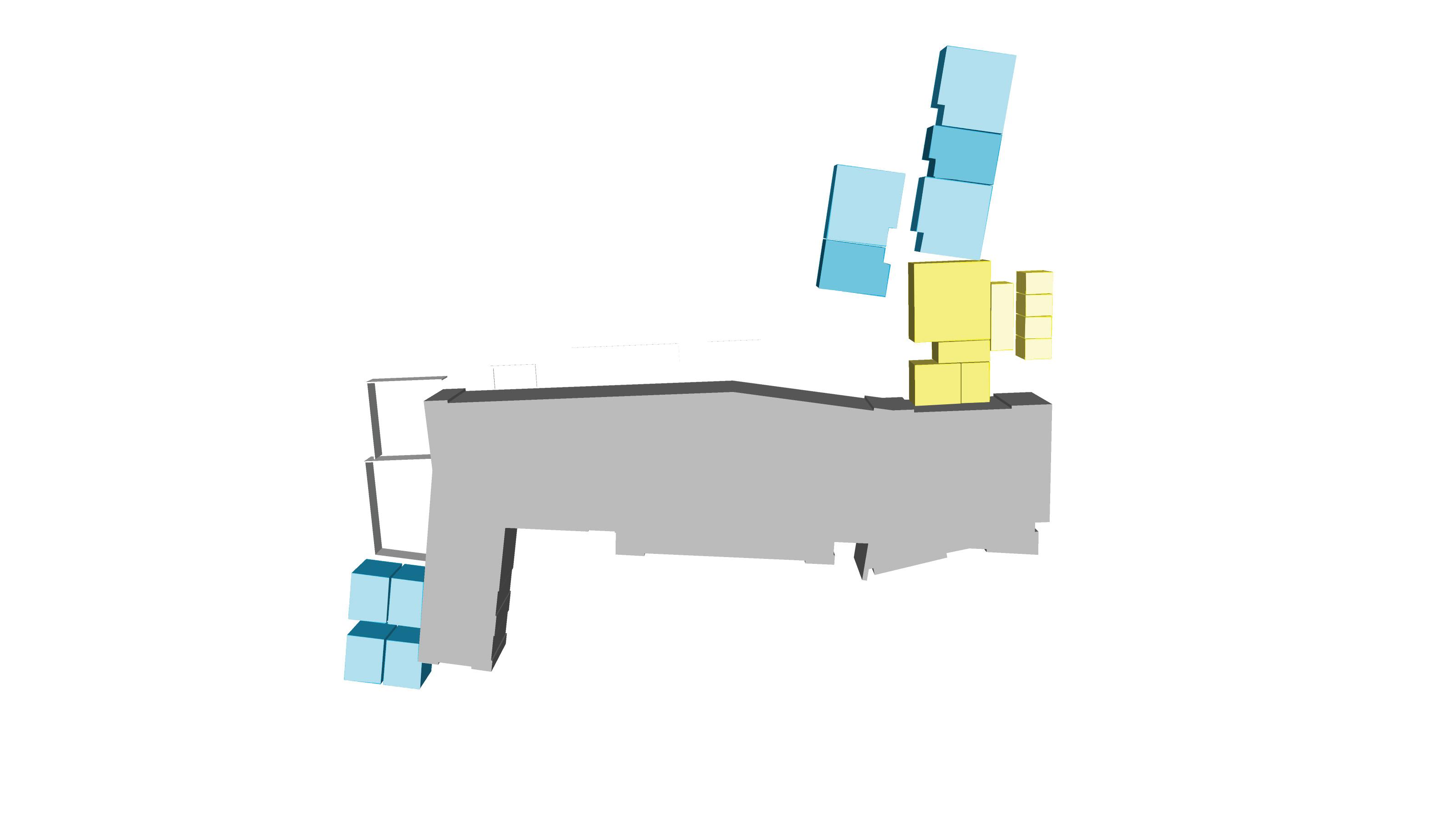
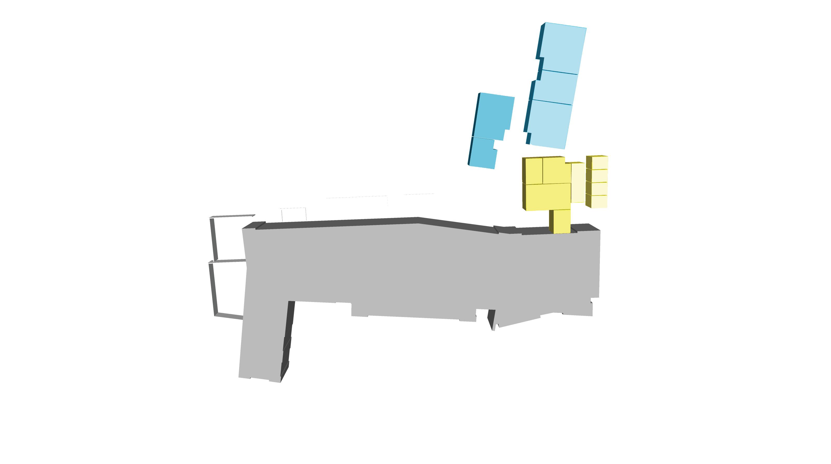
The study and understanding of the existing building’s use and functionality determined the best locations to connect the SGIC Wing Addition to provide the most efficient layout, impacting the existing use of the building as minimally as possible. It was soon determined that the proposed program would be developed into two separate additions.
• The Smart Grid Innovation Center Wing Addition will connect to the north end of the existing building’s lobby to share efficiently the common spaces, provide a continuation of the administrative program which can serve the building as a whole and impact the existing uses minimally.
• The Dynamometer Lab Addition, based on their needs to connect to the existing High Bay labs due to the similarity of functions performed in both spaces.
The organizing idea for the SGIC Wing Addition matches in concept the existing AEC building, with an administrative head, and a double loaded lab corridor spine, which will hold a variety of open flexible laboratories that can be customized to meet specific technical requirements and made available to industry and research communities to perform highly specialized research focused on advanced energy issues. Office areas and “flex lab concepts” from the existing building are used as a model for the Addition.
31
Advanced Energy Center Advanced Energy Center Net Proposed Program First Floor Net Proposed Program Second Floor Dynamometer Lab Addition Lab Spaces Lab Spaces Admin. Spaces Admin. Spaces SGIC Wing Addition SGIC Wing Addition
Laboratory Spaces
The lab program is developed in the SGIC Wing Addition in a double loaded corridor using the campus standard lab module of 330 square feet (10.5 ft. wide and 31.5 ft. deep). The following notes summarize items discussed through programming sessions or recommendations based on items already present in the existing building. These issues will be confirmed and further developed during the future design phases.
• Safety showers and eye wash units will be provided in the laboratory corridors with recessed eye wash. They will be distributed within required travel distance. All laboratory sinks will have a hand held eye wash unit.
• Chemical Storage and Handling
- Laboratories requiring acids, caustics, carcinogens, or solvents will have a separate safety cabinet for each.
- Waste chemicals and solvents will be picked up by an outside agent.
- Chemical storage cabinets will not be vented.
- Gas cylinders will be located inside each lab and piped into the lab equipment as required.
- Lab Compressed Air will be building distributed in the Addition. Per discussions with the users and based on current use in the existing building, this should be considered to be extended to the existing labs.
• General Laboratory Items
- All fume hoods will have a cup sink.
- One sink in each laboratory will be equipped to accept water polishing equipment (i.e. Milli Q).
- A central DI water supply is provided in the AEC but is not distributed through a piping system. Each laboratory user will transfer this water using carboys for their individual use as well as the base water supply for any Milli Q requirements.
- Use of Hydrogen in this building does not require special provisions.
(*) Test-fit based on the proposed conceptual layout (refer to Area Analysis in this chapter)
(**) Deviation due to typical lab module (31’-6” x 10’-6”)
(***) Deviation due to actual dynamometer and control room size per plan layout received (refer to Appendix F)
nasf = Net Assignable Square Feet
sf = Square Feet
32
LABORATORY SPACES Program (nasf) Test-fit* (nasf) Deviation (sf) Energy Research Labs 5,100 5,385 285** Incubator Tenant 2,400 2,455 55** Dynamometer Labs 1,856 1,808 -48*** TOTAL 9,356 9,648 292
(cont’d)
PROGRAMMING
Dynamometer
Energy Research Labs & Incubator Tenants
The Smart Grid Innovation Center Wing will hold an intermix of Energy Research Labs and Incubator Tenants distributed along the two floors of the wing.
The proposed distribution in plan follows a stacking organization of lab spaces of the same module, grouping vertically the typical 900 NSF labs with the 800 NSF incubator lab; and the typical 600 NSF lab and incubators with the 400 NSF incubator lab. This way the proposed structural grid can span the 2 and 3 bay labs (based on the standard lab module described) allowing structure to be located at the lab demizing walls.
Location of laboratory spaces between the proposed first and second floor is based on user requests (Advanced Energy Storage Lab and the Process Engineering Lab match in floor the equivalent labs in the existing building); and on the strategy of placing assigned labs with a large number of fume hoods at the first floor, allowing for easier flexibility if fume hoods need to be added in the top floor.
Laboratory spaces will be adequately sound isolated from adjacent rooms and labs to avoid the current sound issues in the existing AEC lab spaces. Refer to chapter 5 for futher acoustic information on these spaces.
33 Lab #1 Advanced Energy Storage Incubator Tenant #1 Incubator Tenant #2 Incubator Tenant #3 Incubator Tenant #4 Lab #4 Process Engineering Lab #2 Smart Grid Test & Validation Lab #3 Smart Grid Modeling Lab #6 General Lab #5 Distribution Power Engineering Adjacency Necessary Proposed First Floor Proposed Second Floor Energy Research Lab 900 sf (x5) Energy Research Lab 600 sf (x1) Incubator Tenant 800 sf (x1) Incubator Tenant 600 sf (x2) Incubator Tenant 400 sf (x1) Existing High Bay Labs Adjacency
Vertical Adjacency Necessary Control Room #2 Dynamometer Lab Cell #2 Electrical Room #2 Electrical Room #1 Control Room #1
Existing
Storage Flammable Storage Shed Dynamometer Control
414 sf (x2)
Lab
Necessary
Adjacency to
Necessary
Room
Cell 414 sf (x2) Dynamometer Lab Cell #2
These labs are mostly assigned to University Faculty researchers for specific energy research areas, and will hold the required equipment and technology as per each professor’s requirements to fulfill their research needs. Generally labs will hold perimeter casework, including a sink and electrical and data outlets through a wiremold, and provisions for at least one fume hood. Ceiling clouds will provide electrical, data, lab gas and point exhaust services. Refer to room data sheets for specifics on each energy research lab (Appendix D).
(*) Test-fit based on the proposed conceptual layout (refer to Area Analysis in this chapter)
(**) Deviation due to typical lab module (31’-6” x 10’-6”)
34 Legend Energy Research Labs
Wiremold Ceiling Cloud Sink Casework W C S CS W W C S PE FH FH CS L 31’-6” 31’-6” Typical Lab Plan Typical Lab Section Energy Research Lab 900 sf (x5) Energy Research Lab 600 sf (x1) Incubator Tenant 800 sf (x1) Incubator Tenant 600 sf (x2) Incubator Tenant 400 sf (x1) Adjacency Necessary Vertical Adjacency Necessary Control Room #2 Dynamometer Lab Cell #2 Electrical Room #2 Adjacency to Existing Necessary Dynamometer Control Room 414 sf (x2) Dynamometer Lab Cell 414 sf (x2) Locker Point Exhaust Fume Hood L PE FH Energy Research Labs Program (nasf) Test-fit* (nasf) Deviation (sf) Lab #1 - Advanced Energy Storage 900 949 49 Lab #2 - Smart Grid Test & Validation 900 949 49 Lab #3 - Smart Grid Modeling & Simulation 600 620 20 Lab #4 - Process Engineering 900 949 49 Lab #5 - Distribution Power Engineering 900 949 49 Lab #6 - General 900 949 49 TOTAL 5,100 5,365 265
#4 Engineering Grid Grid Adjacency Necessary Floor Energy Research Lab 900 sf (x5) Energy Research Lab 600 sf (x1) Incubator Tenant 800 sf (x1) Incubator Tenant 600 sf (x2) Incubator Tenant 400 sf (x1) Existing High Bay Labs Adjacency Necessary Vertical Adjacency Necessary Control Room #2 Dynamometer Lab Cell #2 Electrical Room #2 Electrical Room #1 Control #1 Adjacency to
Dynamometer Lab Cell #2 Program 5,100 sf Proposed 5,365 sf PROGRAMMING (cont’d)
Existing Necessary
These labs will hold a variety of flexible laboratories that can be customized to meet specific technical requirements and made available to industry and research communities to perform highly specialized research focused on advanced energy issues. Given the needs of each tenant may vary considerably, provision are made for future fume hoods and point exhausts. Casework with a sink is provided on one end of the lab, as well as ceiling clouds with services such as electrical, data and lab gas.
(*) Test-fit based on the proposed conceptual layout (refer to Area Analysis in this chapter) (**) Deviation due to typical lab module (31’-6” x 10’-6”)
35 W S CS L 21’-0” 31’-6” Incubator Tenant Labs
C CS W Typical Incubator Lab Section Typical Incubator Lab Plan Energy Research Lab 600 sf (x1) Incubator Tenant 800 sf (x1) Incubator Tenant 600 sf (x2) Incubator Tenant 400 sf (x1) Labs Adjacency Necessary Vertical Adjacency Necessary Control Room #2 Dynamometer Lab Cell #2 Electrical Room #2 Adjacency to Existing Necessary Legend Wiremold Ceiling Cloud Sink W C S CS Casework Locker Point Exhaust L PE Incubator Labs Program (nasf) Test-fit* (nasf) Deviation (sf) Incubator Tenant Lab #1 400 405 5 Incubator Tenant Lab #2 600 620 20 Incubator Tenant Lab #3 600 620 20 Incubator Tenant Lab #4 800 810 10 TOTAL 2,400 2,455 55 PE Adjacency Necessary Floor Incubator Tenant 800 sf (x1) Incubator Tenant 600 sf (x2) Incubator Tenant 400 sf (x1) Existing High Bay Labs Adjacency Necessary Vertical Adjacency Necessary Control Room #2 Dynamometer Lab Cell #2 Electrical Room #2 Electrical Room #1 Control #1 Adjacency to Existing Necessary Dynamometer Lab Cell #2 Incubator Tenant #3 Incubator Tenant #4 Lab #3 Smart Grid Modeling Lab #6 General Lab #5 Distribution Power Engineering Proposed First Floor Proposed Second Floor Incubator Tenant 800 sf (x1) Incubator Tenant 600 sf (x2) Incubator Tenant 400 sf (x1) Existing High Bay Labs Adjacency Necessary Vertical Adjacency Necessary Control Room #2 Dynamometer Lab Cell #2 Electrical Room #2 Electrical Room #1 Control Room #1 Adjacency to Existing Necessary Storage Flammable Storage Shed Dynamometer Lab Cell #2 Program 2,400 sf Proposed 2,455 sf
Dynamometer Labs
#1
Two Dynamometer Lab Cells will be developed per layout provided the University (refer to Appendix F), where each dynamometer lab is provided with a control room adjacent to it. These labs are to be located adjacent to the existing High Bay labs in the AEC. Given the noisy nature of these lab spaces the dynamometer labs are to be developed providing a sound separation between these and the adjacent spaces (refer to Acoustical strategy for further detail).
In order to provide maximum floor space in the lab area it was requested by the user to place all electrical and mechanical equipment on a second floor immediately above the dynamometer cell. Storage space could also be provided on this second floor. An exterior ventilated shed for flammable storage was requested, and could be placed in the proximity of these labs.
36
Smart Grid Modeling Lab #6 General Lab #5 Distribution Power Engineering Adjacency Necessary Proposed First Floor Proposed Second Floor Energy Research Lab 900 sf (x5) Energy Research Lab 600 sf (x1) Incubator Tenant 800 sf (x1) Incubator Tenant 600 sf (x2) Incubator Tenant 400 sf (x1) Existing High Bay Labs Adjacency Necessary Vertical Adjacency Necessary Control Room #2 Dynamometer Lab Cell #2 Electrical Room #2 Electrical Room #1 Control Room #1 Adjacency to Existing Necessary Storage Flammable Storage Shed Dynamometer Control Room 414 sf (x2) Dynamometer Lab Cell 414 sf (x2) Dynamometer Lab Cell #2 PROGRAMMING (cont’d)
Lab
Advanced Energy Storage Incubator Tenant #1 Incubator Tenant #2 Incubator Tenant #3 Incubator Tenant #4 Lab #4 Process Engineering Lab #2 Smart Grid Test & Validation Lab #3
Dynamometer Cell and Control Room
The interior layout and equipment in these spaces is developed per layout provided by the University. Double doors will access these rooms for ease of equipment transport in and out of the rooms. A sink is also provided at each room. The Dynamometer Lab Cell will require 12’ high ceilings, above which the electrical equipment will be installed allowing for wire and conduit connection through grating to the equipment below.
(*) Test-fit based on the proposed conceptual layout (refer to Area Analysis in this chapter)
(**) Per dynamometer lab plan layout received January 15th, 2015. Rooms are 210”x276”=402 nasf (refer to Appendix F)
37 Engine Bedplate Metal Mesh Grating Sink EB M S
EB M EB S S 36’-2” 17’-6” 23’-0” Section Electrical Room Control Room Dynamometer Lab Cell Dynamometer Lab Cell Control Room Plan Dynamometer Labs Program (nasf) Test-fit* (nasf) Deviation (sf) Dynamometer Test Cell #1 414 402** -12 Dynamometer Test Cell #2 414 402** -12 Control Room #1 414 402** -12 Control Room #2 414 402** -12 Storage 200 200 0 TOTAL 1,856 1,808 -48
Legend
SC SC SC Storage
Work
WB WB WB WB WB WB
Cabinet
Bench / Desk SC
Energy Research Lab 900 sf (x5) Energy Research Lab 600 sf (x1) Incubator Tenant 800 sf (x1) Incubator Tenant 600 sf (x2) Incubator Tenant 400 sf (x1) Labs Adjacency Necessary Vertical Adjacency Necessary Control Room #2 Dynamometer Lab Cell #2 Electrical Room #2 Adjacency to Existing Necessary Dynamometer Control Room 414 sf (x2) Dynamometer Lab Cell 414 sf (x2) Incubator Tenant #3 Incubator Tenant #4 Lab #4 Process Engineering Lab #2 Smart Grid Test & Validation Lab #3 Smart Grid Modeling Adjacency Necessary Proposed Second Floor Energy Research Lab 900 sf (x5) Energy Research Lab 600 sf (x1) Incubator Tenant 800 sf (x1) Incubator Tenant 600 sf (x2) Incubator Tenant 400 sf (x1) Existing High Bay Labs Adjacency Necessary Vertical Adjacency Necessary Control Room #2 Dynamometer Lab Cell #2 Electrical Room #2 Electrical Room #1 Control Room #1 Adjacency to Existing Necessary Dynamometer Control Room 414 sf (x2) Dynamometer Lab Cell 414 sf (x2) Dynamometer Lab Cell #2 Program 1,856 sf Proposed 1,808 sf
Administrative Spaces
The organization of these spaces as proposed provide a layout which condenses the existing and new administration areas to serve as a whole for the building. The administrative program is developed based on three main factors:
• Proximity to the adjacent existing administrative area
• Main Conference Room layout and circulation, being one of the predominant spaces in the SGIC Wing Addition
• Office & cubicle area layout, which ties into the existing providing coherent circulation and functionality
Other than the Main Conference Room, where the provision for presentations and projections grant a concealed perimeter, the rest of the office and student spaces have been proposed to profit as much as possible from the natural daylight, or indirect whenever immediate adjacency to the exterior was not possible.
The proposed layout connects the Addition through most of the north facade of the existing building’s administrative area, providing continuation of the existing open office space which allows for the office area to function in conjunction with the existing one.
An open atrium will allow for a pre-function space adjacent to the Main Conference Room, and will allow for the Student Poster Display Area. This open atrium will also provide a new glass partition to the north of the existing Conference Room and Break Room at the existing building, filling these spaces with indirect natural light.
This functional layout provides with additional net area at the connection and at the generous main corridor on the second floor, allowing for open meeting and workstation spaces. This results in a higher net square footage proposed, as shown in the Area Analysis in this chapter. This additional program is proposed, as a single “bridge” connection between both buildings did not allow for a cohesive functioning of the administration areas. A siingle connection would completely separate the additional administrative program from the existing, thereby losing the desired functionality of the building as a whole.
(*) Test-fit based on the proposed conceptual layout (refer to Area Analysis in this chapter)
38
ADMINISTRATIVE SPACES Program (nasf) Test-fit* (nasf) Deviation (sf) Meeting & Miscellaneous 3,210 3,526 316 Offices & Cubicles 1,560 1,552 -8 TOTAL 4,770 5,078 308
(cont’d)
PROGRAMMING
Meeting & Miscellaneous Spaces
The Meeting spaces will be comprised of the Main Conference Room for board meetings and the Small Conference Room for up to 10 people, and will supplement the existing conference and meeting rooms in the AEC facility.
The Main Conference Room is proposed to be located on the first floor in close proximity to the existing lobby, for ease of access. The program requires the Student Poster Display Area and the Food Service/Staff Break room to be immediately adjacent to the Main Conference Room.
The remaining program spaces (Small Conference Room, Student Workstations and Office Storage) are developed in the second floor of the Addition, above the Main Conference Room. This allows for the proposed office program to be equal on each floor and stack on both levels, similarly to its layout in the existing building.
(*) Test-fit based on the proposed conceptual layout (refer to Area Analysis in this chapter)
39 Existing Lobby Main Conference Room Adjacency to Existing Necessary Poster Display Area 400 sf (x1) Student Workstations 600 sf (x1) Faculty O ces 120 sf (x8) Cubicles 100 sf (x6) Atrium/ Display Food Service Storage Student Workstations Sm. Conf. Room Adjacency Necessary Main Conference Room 1400 sf (x1)
Meeting & Miscellaneous Spaces Program (nasf) Test-fit* (nasf) Deviation (sf) Main Conference Room 1,400 1,295 -105 Food Service / Staff Break Room 250 330 80 Small Conference Room 200 228 28 Poster Display Area 400 646 246 Student Workstations 600 667 67 Office Storage 360 360 0 TOTAL 3,210 3,526 316 Offices & Cubicles Program (nasf) Test-fit* (nasf) Deviation (sf) Faculty Offices (x8) 960 912 -48 Cubicles (x6) 600 640 40 TOTAL 1,560 1,552 -8
Main Conference Room
This room is to be designed to hold the Advanced Energy Center Advisory Board meetings for 35 board members, as well as presentations and events in a classroom layout for up to 50 people. This room will have state-of-theart audio-visual equipment, and the required acoustical wall and ceiling treatment to enhance intelligibility of speech during meetings. A Food Service Room is to be adjacent and connected through 2 sets of doors for ease of circulation. The Food Service Room also functions as a Staff Break Room when no meetings or events are being held at the Main Conference Room.
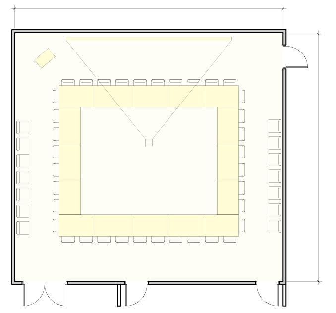
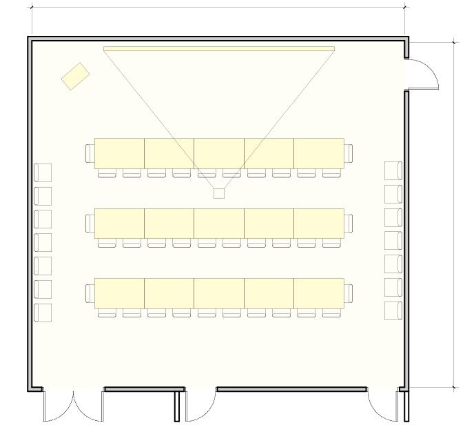
40 Section Podium Roll-down Projection Screen Projector, ceiling mounted Lockable Credenza P PS PR Legend C P PS PR C 37’-4” 35’-5” P PS PR C P PS
Layout B: Classroom (50 seats) 600 sf (x1) Faculty O ces 120 sf (x8) Cubicles 100 sf (x6) Main Conference Room 1400 sf (x1)
Program 1,400 sf Proposed 1,295 sf 37’-4” Layout A: Board Room (35 seats) Food Service Room 35’-5” Food Service Room
PROGRAMMING (cont’d)
An open area for display of the work and achievements developed in the Advanced Energy Center is to be adjacent to the Main Conference Room. Easels will be used for poster display. The proposed display space is also used as pre-function space for the Main Conference Room, and develops as a double height space atrium to introduce natural light through a skylight to the adjacent interior spaces surrounding this atrium.
41
Display Area
Student Poster
Display Easels E Legend
E E Section 20’-6” 22’-2” Plan Adjacency to Existing Necessary Poster Display Area 400 sf (x1) Student Workstations 600 sf (x1) Faculty O ces 120 sf (x8) Cubicles 100 sf (x6) Main Conference Room 1400 sf (x1) Program 400 sf Proposed 646 sf
COMMUNAL - STUDENT AREA
Student Workstations
An enclosed room is provided with workstations for students to be able to set their computers outside of the laboratory spaces. The proposed room is adjacent to the atrium and the connection corridor to the Smart Grid Innovation Center Wing, which is intended to be glazed, so as to provide this space with as much natural light as possible. It is in this connecting corridor where space for open workstations can be located with an overview to the landscape looking west of the proposed building.
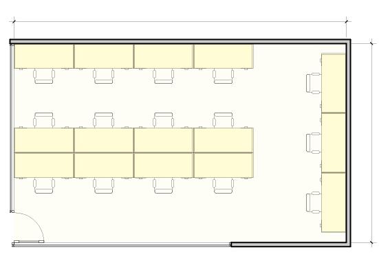
42
Student Desks Glass Wall D G Legend Section D G 33’-4” 20’-0” Plan Poster Display Area 400 sf (x1) Student Workstations 600 sf (x1) Faculty O ces 120 sf (x8) Cubicles 100 sf (x6) Main Conference Room 1400 sf (x1)
Program 600 sf Proposed 667 sf
PROGRAMMING (cont’d)
Faculty Offices
The faculty offices are to match the existing offices in the AEC building, these being in private rooms and with direct access to daylight. Two blocks of 4 offices with an open support area for 3 cubicles are stacked in the proposed layout, and fully connected to the existing open office area in the existing building.
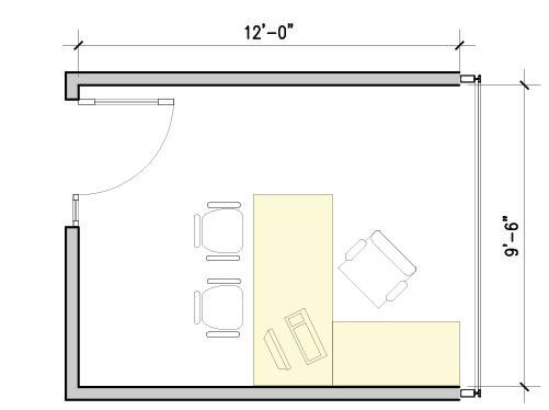
43
Desk Sun Shades D SH Legend Section D SH 9’-8” 12’-0” Plan Poster Display Area 400 sf (x1) Student Workstations 600 sf (x1) Faculty O ces 120 sf (x8) Cubicles 100 sf (x6) Main Conference Room 1400 sf (x1) Program 960 sf Proposed 912 sf
Similar to the open office layout in the existing AEC building, the cubicles are to be located in an open space adjacent to the private offices. Cubicle partitions are to be 5’-0” A.F.F., offering some privacy from the adjacent cubicles.
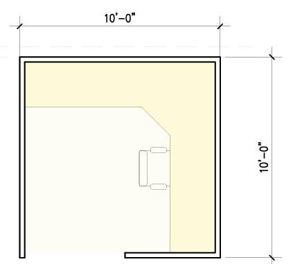
44 Section D CP Desk Cubicle Partitions D CP Legend Cubicles
10’-0” 10’-0” Plan Student Workstations 600 sf (x1) Faculty O ces 120 sf (x8) Cubicles 100 sf (x6) Main Conference Room 1400 sf (x1)
Program 600 sf Proposed 640 sf
PROGRAMMING (cont’d)
Area Analysis & Tabulation
The following area analysis takes into account the Initial Program request (14 January 2015 — refer to Appendix E) and the Developed Program due to clarifications and user requests at presentation and user meetings (April 1st, 2015). Several factors affected the achievement of the initial program estimate of 20,000 GSF for this Smart Grid Innovation Center Addition:
• Due to lab functionality the initial single addition had to be divided into two separate additions (the SGIC Wing Addition & the Dynamometer Lab Addition), which impacts ultimately on the efficiency of the combined addition.
• To provide a functional connection between the existing and proposed administration areas, for ease of circulation and workstation utilities sharing, the SGIC Wing was proposed to connect with a wider program to the existing allowing for an atrium which can act as pre-function space for the Main Conference Room and provides with natural light to the existing conference and break room spaces at the connection. This results in a more functional layout.
• The need for a 2nd floor on the Dynamometer Lab Addition for electrical equipment increased the initial GSF for this area.
45 SMART GRID INNOVATION CENTER WING ADDITION Initial Program (nasf) 14 January 2015 Developed Program (nasf) 1 April 2015 Test-fit (nasf) Deviation (sf) Administrative Spaces 4,380 4,770 5,078 308 Laboratory Spaces 7,500 7,500 7,840 340 SGIC sub-total net 11,860 12,270 12,918 648 SGIC sub-total gross 18,000 18,600 20,939 2,339 Efficiency (net area to gross area ratio) 65.9% 65.9% 61.7% DYNAMOMETER LABS ADDITION Initial Program (nasf) 14 January 2015 Developed Program (nasf) 1 April 2015 Test-fit (nasf) Deviation (sf) Dynamometer labs sub-total net 1,656 1,856 1,808 -48 Dynamometer labs sub-total gross 2,000 3,200 3,580 380 Efficiency (net area to gross area ratio) 82.8% 58.0% 50.5% COMBINED ADDITIONS Initial Program (nasf) 14 January 2015 Developed Program (nasf) 1 April 2015 Test-fit (nasf) Deviation (sf) Total net 13,516 14,126 14,726 600 Total gross 20,000 21,800 24,519 2,719 Efficiency (net area to gross area ratio) 67.6% 64.8% 60.0%
Smart Grid Innovation Center Wing Addition
First Floor
The administration area is immediately adjacent to the existing building through a wide connection bar which allows for additional open meeting area and an atrium as pre-function space adjacent to the Main Conference Room, which can function as the desired Student Poster Display Area. The lab wing develops in a double loaded corridor to the north beyond the administration area.
(*) Program clarification - Food service/break room as a separate function from the Small Conference Room (**) Faculty Offices to match SBU Standard Faculty Office (120 nasf each) (***) Deviation due to typical lab module (31’-6” x 10’-6”)
46
1 2 3 4 5 6 7 8 9 10 1 2 3 4
SGIC Wing First Floor Space Initial Program (nasf) 14 January 2015 Developed Program (nasf) 1 April 2015 Test-fit (nasf) Deviation (sf) 1 Atrium / Student Poster Display Area 400 400 646 246 2 Main Conference Room 1,400 1,400 1,295 -105 3 Food Service / Break Room 0 250 226 -24 4 Cubicles (x3) 300 300 340 40 5 Faculty Offices (x4) 400 480 456 -24 6 Incubator Tenant #2 600 600 620 20 7 Advanced Energy Storage: Lab #1 900 900 949 49 8 Distribution Power Engineering: Lab #5 900 900 949 49 9 Incubator Tenant #3 600 600 620 20 10 General: Lab #6 900 900 949 49 SGIC Wing sub-total net 6,400 6,730 7,050 320 SGIC Wing sub-total gross 9,000 9,500 11,175 1,675 Net area to gross area ratio 71.1% 70.8% 63.1%
(cont’d) *** *** *** *** *** * **
PROGRAMMING
(*) Faculty Offices to match SBU Standard Faculty Office (120 nasf each)
(**) Deviation due to typical lab module (31’-6” x 10’-6”)
47
Second Floor Connection corridor between existing building and lab wing allows for additional open workstation space. 1 2 3 4 5 6 7 8 9 10 11 1 2 3 SGIC Wing Second Floor Space Initial Program (nasf) 14 January 2015 Developed Program (nasf) 1 April 2015 Test-fit (nasf) Deviation (sf) 1 Small Conference Room 200 200 228 28 2 Student Workstations 600 600 667 67 3 Cubicles (x3) 300 300 300 0 4 Faculty Offices (x4) 400 480 456 -24 5 Office Storage 360 360 360 0 6 Incubator Tenant #1 400 400 405 5 7 Incubator Tenant #4 800 800 810 10 8 Smart Grid Test & Validation: Lab #2 900 900 949 49 9 Smart Grid Modeling & Simulation: Lab #3 600 600 620 20 10 Process Engineering: Lab #4 900 900 949 49 SGIC Wing sub-total net 5,460 5,540 5,744 204 SGIC Wing sub-total gross 9,000 9,100 9,764 664 Net area to gross area ratio 60.7% 60.9% 58.8%
Smart Grid Innovation Center Wing Addition
** ** ** ** ** *
Dynamometer Labs Addition — First Floor
The proposed provides a corridor for easy access of equipment which needs to be moved between the existing High Bay lab and the Dynamometer Labs. Access from the exterior to this corridor allows for any equipment which does not need to access the building through the loading dock, for ease of use of these labs.
(*) Per dynamometer lab plan layout received January 15th, 2015. Rooms are 210”x276”=402 nasf (refer to Appendix F)
48
1 2 3 4
Dynamometer First Floor Space Initial Program (nasf) 14 January 2015 Developed Program (nasf) 1 April 2015 Test-fit (nasf) Deviation (sf) 1 Dynamometer Test Cell #1 414 414 402* -12 2 Dynamometer Test Cell #1 414 414 402* -12 3 Control Room #1 414 414 402* -12 4 Control Room #2 414 414 402* -12 Dynamometer sub-total net 1,656 1,656 1,608 -48 Dynamometer sub-total gross 2,000 2,000 2,192 192 Net area to gross area ratio 82.8% 82.8% 73.3% PROGRAMMING (cont’d)
Dynamometer Labs Addition — Second Floor
Due to the need of freeing floor space in the Dynamometer Test Cells, a second floor with electrical equipment has been provided, which adds considerably to the GSF.
(*) Per meeting with Dr. Mamalis & Dr. Lawler April 1st, 2015 (electrical room above dynamometer test cell required)
(**) Per meeting with Dr. Mamalis & Dr. Lawler April 1st, 2015 (storage space required)
(***) Assumed Gross SF of second floor (not included in initial program GSF)
49
1 2 3
Dynamometer Second Floor Space Initial Program (nasf) 14 January 2015 Developed Program (nasf) 1 April 2015 Test-fit (nasf) Deviation (sf) 1 Electrical Room #1 0 (402) (402) 0 2 Electrical Room #2 0 (402) (402) 0 3 Storage 0 200 200 0 Dynamometer sub-total net 0 200 200 0 Dynamometer sub-total gross 0 1,200 1,388 188 Net area to gross area ratio 0 16.7% 14.4% * * ** ***
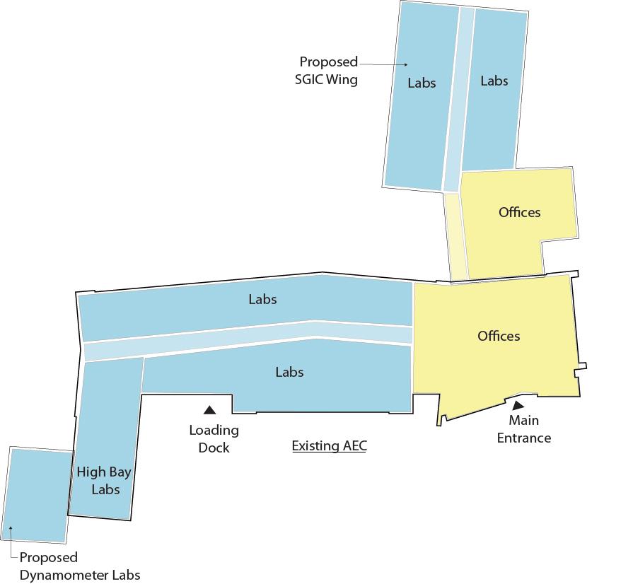
50 Advanced Energy Center Advanced Energy Center 1. Existing Basement 1 1. Dynamometer Labs 2. Atrium/Display Area 3. Food Service/Break Room 4. Main Conference Room 5. Cubicles 6. O ces 7. Lab 8. Stair 9. Mechanical Room 1 Basement Floor First Floor 3 4 5 6 7 8 7 7 7 7 2 9 BASE SCHEME Advanced Energy Center Advanced Energy Center 1. Skylight 2. Stair Bulkhead 3. Only lab exhaust fans on roof 1 2 3 1. Open to Below 2. Small Conference Room 3. Student Workstations 4. O ce Storage 5. Cubicles 6. O ces 7. Lab 8. Stair 9. Mechanical Room 10. Outdoor Mechanical Equipment 1 3 4 5 6 7 8 9 1 Second Floor Roof 7 7 7 7 2 10 First Floor Second Floor Proposed Base Scheme N
04. Test Fit
Proposed Base Scheme
The proposed Base Scheme is divided into the SGIC Wing Addition, which ties to the north end of the vestibule of the existing AEC building, and Dynamometer Labs Addition, which ties to the existing High Bay Lab at the southwest end of the existing AEC building.
Smart Grid Innovation Center Wing Addition — Base Scheme
The required program includes both administrative and laboratory areas, and it is to use to the extent possible the common services of the existing building, which includes the existing main entrance, as a separate entrance for the Addition is not required. To this effect, and disrupting at a minimum the existing program and use of the building, the proposed location for the SGIC Wing Addition will tie into the existing lobby through the north façade, providing a similar program distribution to the existing, with the administrative area adjacent to the main access to the building, and a lab wing developing from it.
Interaction and spontaneous engagement of users in this building has been considered an important factor contributing to the development of the existing building, and translated to the design of the proposed Addition, intermixing in the layout research labs with tenant spaces.
This proposed SGIC Wing Addition develops perpendicularly to the existing building to maximize the daylight and views of the proposed program spaces, as well as avoiding impacting the existing daylight and views of the current building spaces. The perpendicular
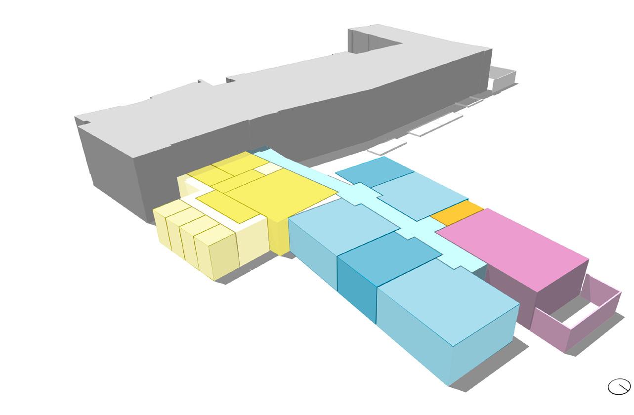
approach also provides a larger presence of the proposed building complex to Innovation Road, which constitutes the only current access to the facility, and allows for visual ties to the future buildings developing north of the proposed site on the Research and Development Campus per the SBU Master Plan. The architectural language proposed will match the existing building to create a unified building complex, through the use of brick, metal panels, and glass curtain wall systems on the exterior, and through a design vocabulary comparable to the existing in the interior.
SGIC Wing Interior
The interior space is developed into two floors. The program is divided into the administrative area, which is immediately adjacent to the existing building and acts as a connection to it, and the lab wing, which is developed in a double loaded corridor.
The Administrative area will include a Main Conference Room to hold board meetings for 35 people as well as classroom/presentation layout for approximately 50 people, with an adjacent Food Service Room which also acts as a Staff Break Room area. A Student Workstation room, an 8 to 10 person Small Conference Room, eight faculty offices and six support cubicles complete the administrative program. A double height pre-function space will articulate the access to the Main Conference Room from the existing lobby, and will permit the display of the work developed in the facility. The faculty offices are developed at the east façade on both floors, profiting from natural daylight and views.
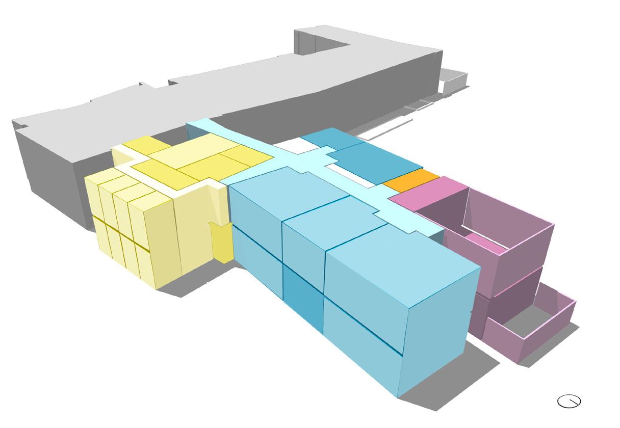
51
Advanced Energy Center Admin. Area Existing Lobby Laboratory Area MEP room Advanced Energy Center Admin. Area Existing Lobby Laboratory Area Smart Grid Innovation Center Wing Addition Second Floor Smart Grid Innovation Center Wing Addition First Floor N N
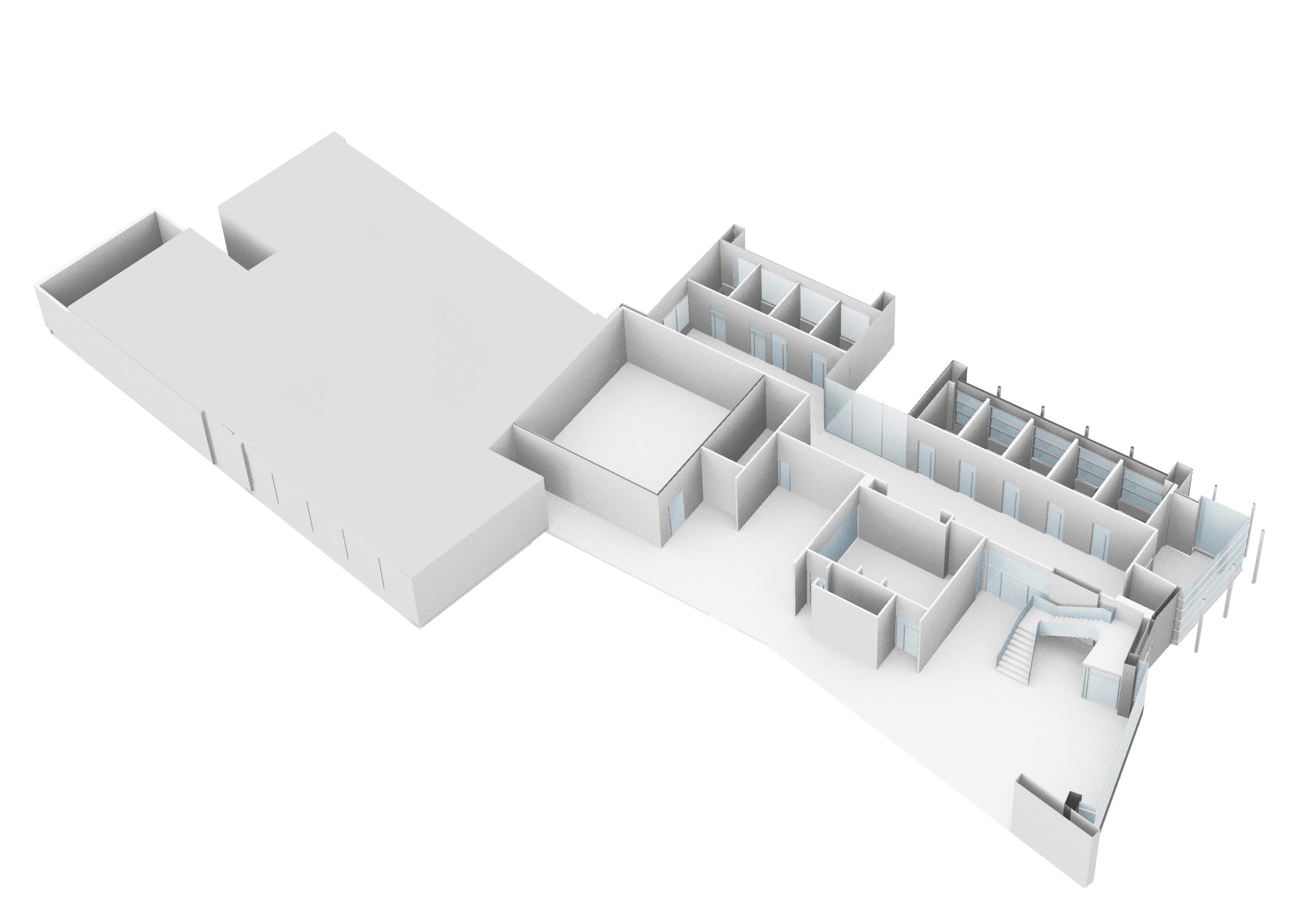


This interior layout is driven by the functional circulation between the proposed and the existing spaces, creating a cohesive administration area to serve both laboratory wings. Proposed circulation allows for the office and cubicle spaces to have a common private circulation secured from the public access spaces.
The Main Conference Room would be accessed through the main lobby, but would also have a private access through the Food Service / Staff Break Room from the private office area. These new offices will also have a more direct access to the added lab wing, as they will be mainly holding researchers from these added laboratories.
Proposed SGIC Wing Lab Space ProposedSGICWing Admin. Space ExistingAEC Admin. Space Main Entrance 1. Existing Conference Room 2. Atrium/ Display Area 3. Main Conference Room 4. O ces & Cubicles 5. Existing OFfices & Cubicles 6. Existing Lobby 1 2 3 4 5 1 Existing AEC Lab Space Proposed SGIC Wing Lab Space ProposedSGICWing Admin. Space ExistingAEC Admin. Space Main Entrance First Floor 1. Existing Conference Room 2. Atrium/ Display Area 3. Main Conference Room 4. O ces & Cubicles 5. Existing OFfices & Cubicles 6. Existing Lobby 1 2 3 4 5 1 6 TEST FIT (cont’d)
First Floor
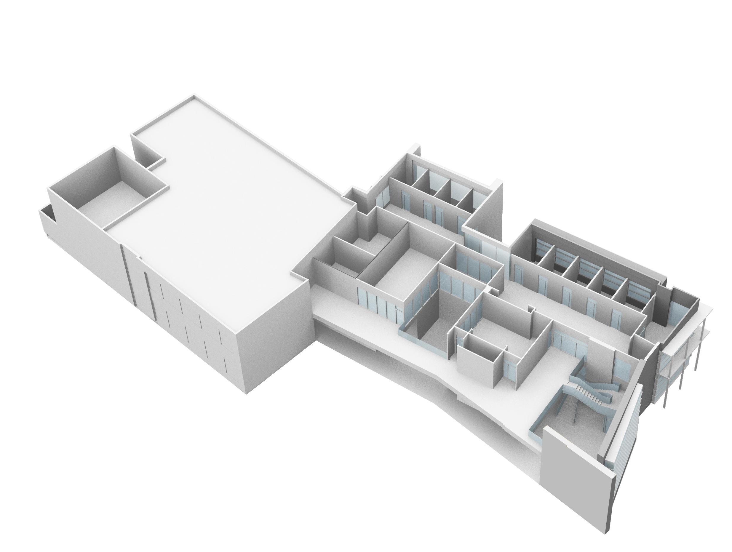


53 Main Entrance ProposedSGICWing Admin. Space ExistingAEC Admin. Space Proposed SGIC Wing Lab Space 1. Break Room 2. Double Height Space 3. Student Workstations 4. O ce Storage 5. O ces & Cubicles 6. Existing O ces & Cubicles 1 2 3 4 5 6 Main Entrance Existing AEC Lab Space ProposedSGICWing Admin. Space ExistingAEC Admin. Space Second Floor Proposed SGIC Wing Lab Space 1. Break Room 2. Double Height Space 3. Student Workstations 4. O ce Storage 5. O ces & Cubicles 6. Existing O ces & Cubicles 1 2 3 4 5 6 Second Floor
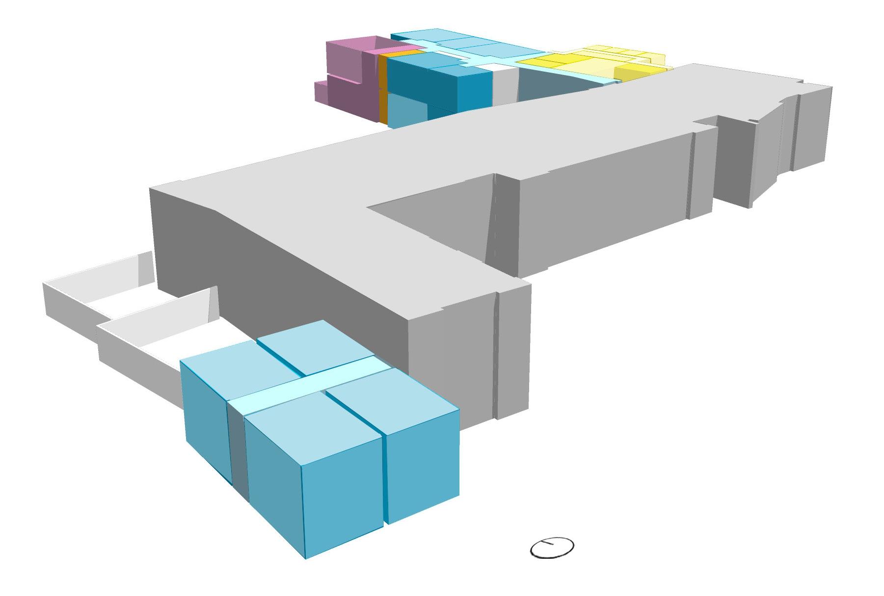
54
Advanced Energy Center
Smart Grid Innovation Center Wing Addition
Existing High Bay Lab N
Dynamometer Labs Addition
The proposed design vocabulary for the interior administration spaces is as follows:
• Main Conference Room: carpet flooring with wood base, acoustically treated walls and an acoustical tile ceiling.
• Small Conference Room: carpet flooring with rubber cove base, painted drywall and glazed partitions, and acoustic ceiling tile.
• Student Workstations: carpet flooring with rubber cove base, painted drywall and glazed partitions and acoustic ceiling tile.
• Office spaces: carpet flooring with rubber cove base, painted drywall partitions and acoustic ceiling tile. Hard walled offices will be furnished with wall mounted system furniture. Open cubicle areas will have mobile systems furniture with ergonomic chairs and workstations.
• Display area and circulation: stone tile flooring with stone base, painted drywall partitions and metal mesh grid ceiling in the circulation spaces. The double height space is topped by a skylight.
• Office Storage: vinyl flooring with vinyl base, painted drywall and exposed ceilings.
• Toilets: Ceramic tile flooring, ceramic tile wainscot and painted drywall partitions, and drywall ceilings, to match the existing toilets. Fixtures are per SBU standards.
Lab area houses four incubator tenant labs and six Energy Research Laboratories based on the campus standard lab module (31’-6” deep by 10’-6” wide). Mechanical spaces will be housed at the end of this lab wing.
The proposed design vocabulary for the interior laboratory and mechanical spaces is as follows:
• Lab spaces: Vinyl flooring with vinyl base, epoxy painted drywall partitions with drywall ceiling clouds containing lab services on an otherwise exposed painted ceiling.
• Lab corridor spaces: Vinyl flooring with vinyl base, epoxy painted drywall partitions with a metal mesh grid ceiling to hide the services.
• Mechanical spaces: sealed concrete flooring, CMU walls with exposed ceilings.
SGIC Wing Exterior
The architectural language is to match the existing, which complements the material usage of the neighboring Center of Excellence in Wireless and Information Technology (CEWIT) building. The proposed design vocabulary for the exterior of the building is as follows:
• Zinc panels
• Roman brick
• Curtain wall and glazing systems with anodized aluminum finish and high performance low-E glazing. East and West exposures to have a sunshade roller system.
• Mechanical spaces to be cladded (1st floor) or screened (2nd floor) with corrugated galvanized zinc metal sheets, with acoustical painted aluminum louvers.
Dynamometer Labs Addition
The Dynamometer Labs will be connected to the existing High Bay lab due to the equivalent function to be developed on these spaces. It is proposed to locate the Dynamometer Labs to the West of the existing, to minimize impact on the current building layout. Work to access the existing outdoor equipment would need to be done to allow for this Addition. This Addition will house two dynamometer labs along with two control rooms in a double height space with a metal grated second floor where the electrical and mechanical equipment specific to these labs will be installed to allow for the most efficient use of the floor space for research.
Dynamometer Labs Interior
These dynamometer labs need acoustical treatment to minimize the noise impact of the processes developed in them, as well as a blast security factor. Refer to acoustical narrative for specifics.
• Epoxy sealed concrete floors with vinyl base, CMU walls and a painted exposed ceiling.
Dynamometer Labs Exterior
Adjacent to the existing High Bay Lab of the AEC building it is to match in material language.
• Roman brick
55 TEST FIT (cont’d)
56 First Floor Plan 1. Main Conference Room 2. Mechanical 3. Vertical Circulation 4. Incubator Labs 5. Energy Research Labs 6. Office Space 7. Food Service/Break Room 8. Atrium/Student Poster Display Area 9. Dynamometer Labs 1 3 4 AEC 2 4 5 5 5 8 7 6 9 9 N Lobby Meeting Office Space High Bay Lab Labs Labs Labs TEST FIT (cont’d)
57 Second Floor Plan 1. Student Workstations 2. Mechanical 3. Vertical Circulation 4. Incubator Labs 5. Energy Research Labs 6. Office Space 7. Office Storage 8. Small Meeting Room 1 2 3 4 5 6 7 7 8 N AEC Break Room Office Space High Bay Lab Labs Labs Labs
58 TEST FIT (cont’d) Extended Innovation Road West–East Section through SGIC Wing Addition lab double loaded corridor, looking North Lab Lab Outdoor Mechanical Equipment Mechanical
59 Proposed Additional Parking Innovation Road Existing Building (AEC) Proposed SGIC Wing Lab Lab Lab Lab Lab Lab Main Conference Room Student Workstations Atrium/ Display Student Workstations Main Conference Room Cubicles Cubicles Offices Offices West-East Section through SGIC Wing Addition administrative area, looking North North-South Section through SGIC Wing Addition, looking East
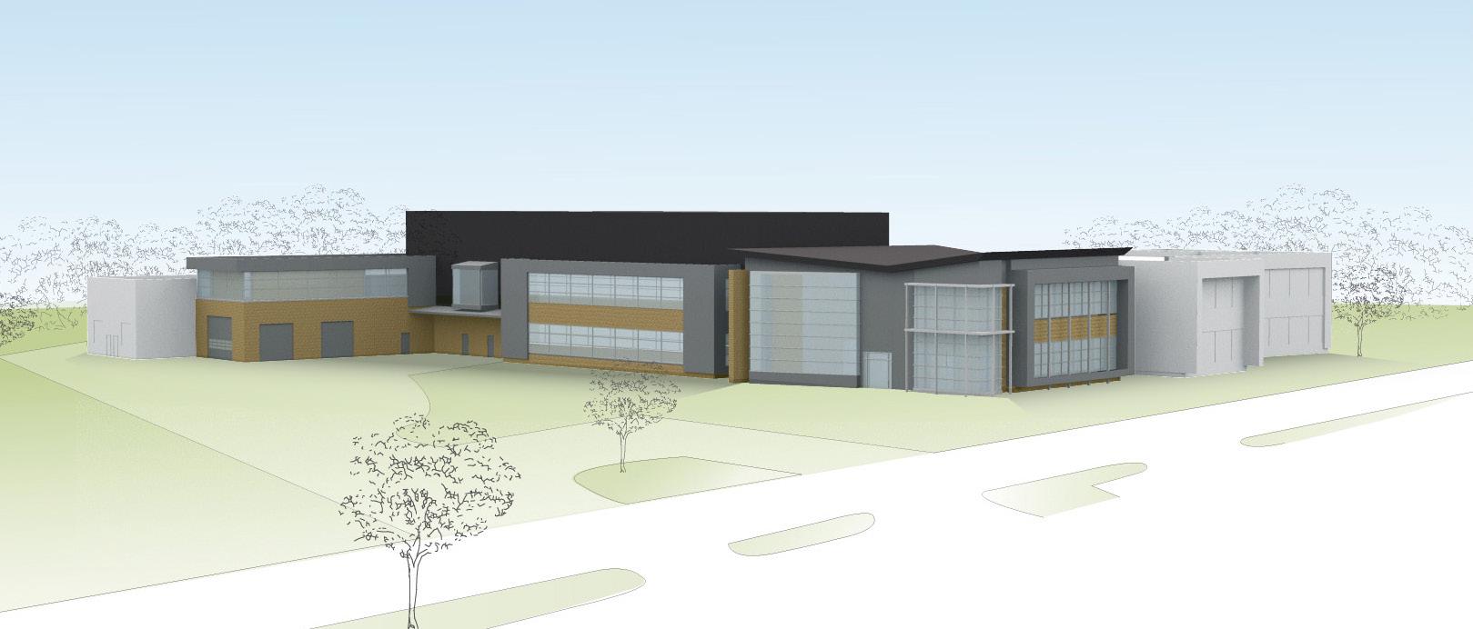
Perspective 01 - looking northwest from the existing parking lot
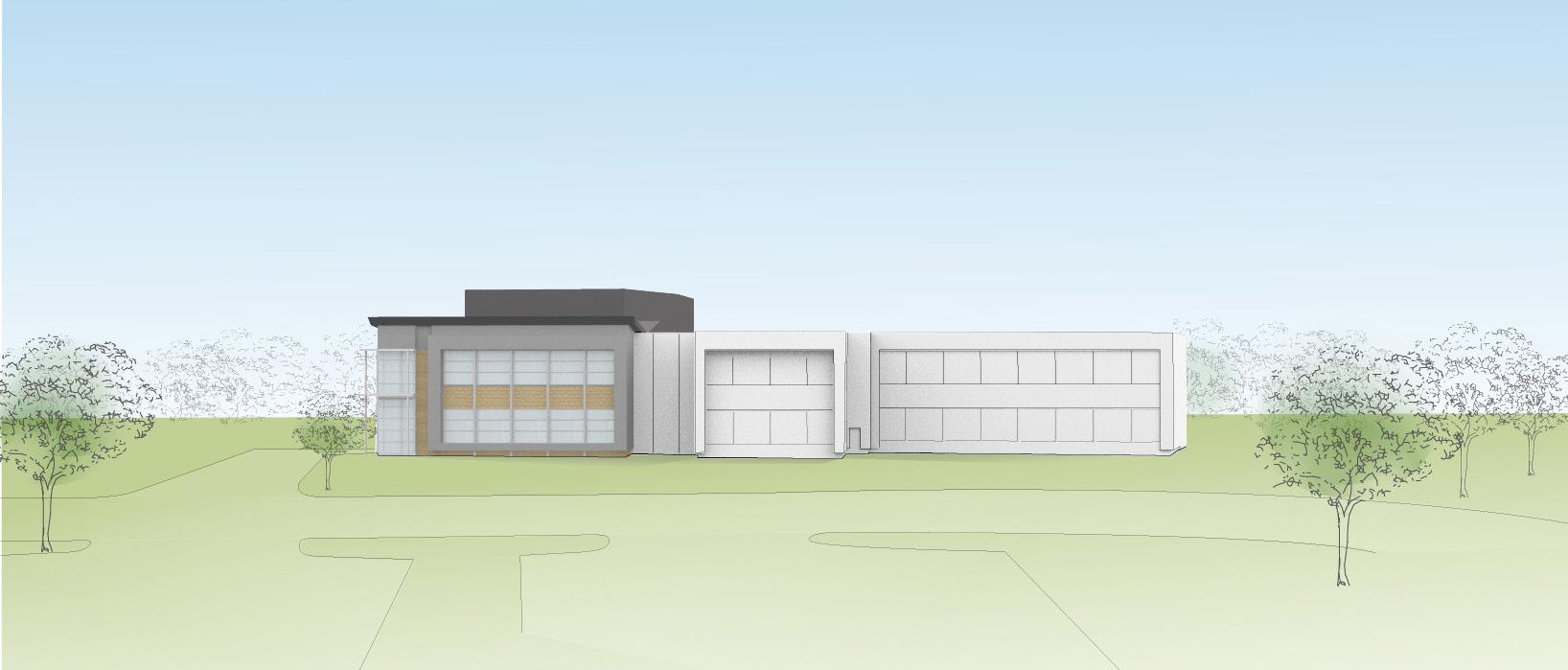
Perspective 02- looking west from the proposed parking lot
60
TEST FIT (cont’d)
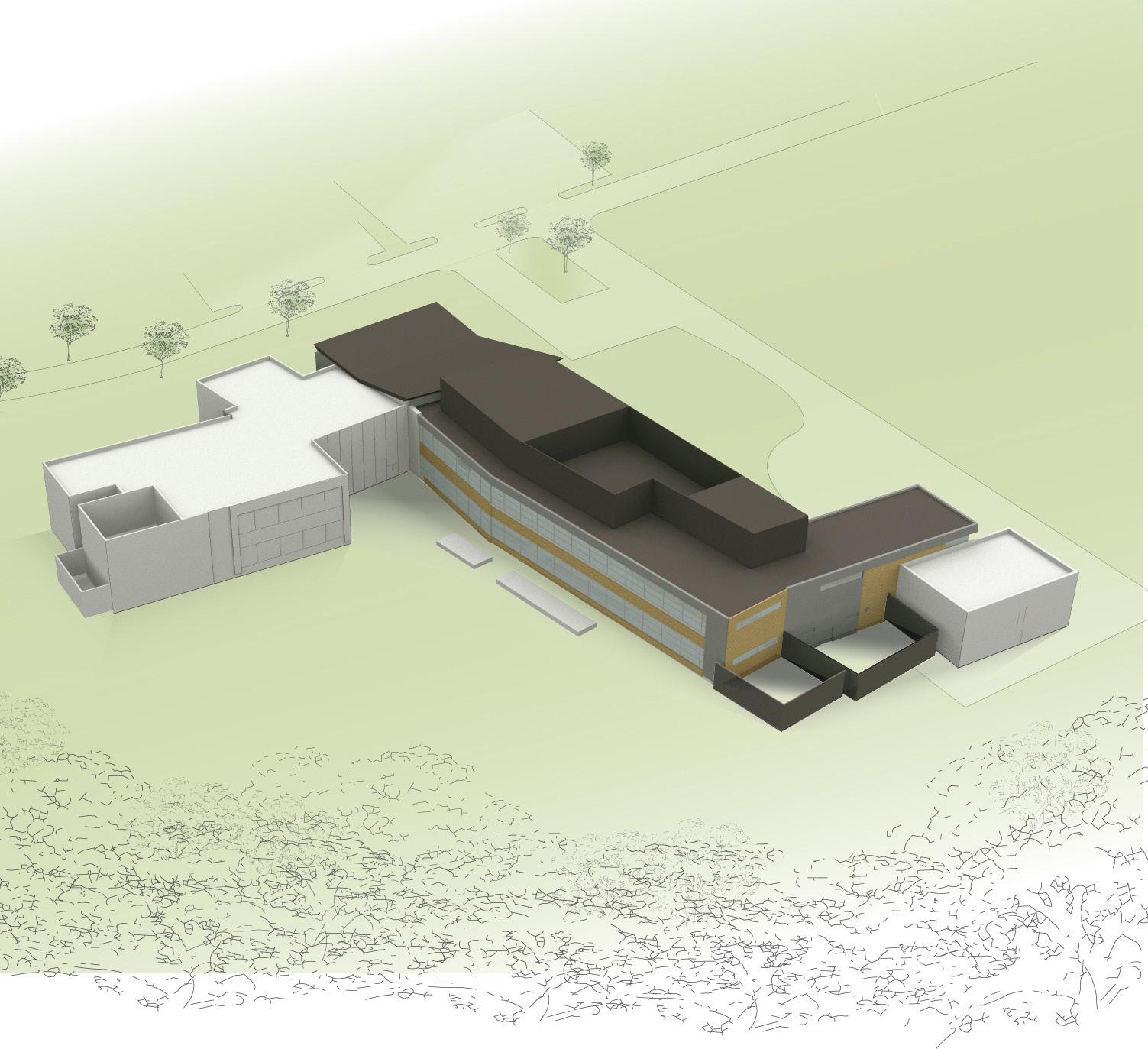
Perspective 03- aerial view looking southeast
61
SGIC Wing Addition Options
The following options are based on modifications to the Base Scheme. Refer to the cost estimation for pricing of these options.
SGIC Wing Option #1 — Service Elevator
This option includes a service elevator adjacent to the administrative area and as close as possible to the existing AEC lobby to be able to serve both buildings. The elevator will solve the current loading needs of the existing building as currently most of the larger and heavier equipment has to be loaded into the building by use of the crane at the High Bay lab due to the small size and capacity of the existing elevator. The existing elevator is located far from the existing lobby. This constitutes an issue in the current layout, which will be solved with the location of the proposed service elevator.
This proposed service elevator will be a hydraulic elevator which would serve the two floors in the basic scheme, and access the basement in options #2 and #3.
• Stainless steel walls & ceiling, heavy duty rubber floor.
• Up to 5000 LBS loading capacity.
SGIC Wing Option #2 — Core & Shell Basement
This option adds approximately 3,000 SF of basement which is to be treated as a shell space for future use. Capped services are to be provided for this shell space as it may be occupied by future labs which may profit from no exposure to daylight. Vertical circulation needs to access this basement (both elevator and stair access), so a second access stair which connects the ground floor to this basement is included.
SGIC Wing Option #3 Basement w/ Microscopy Suite, Storage & Mechanical
This option adds a full basement to house the existing Microcopy Suite (approx. 2,000 SF), Storage space (approx. 2,000 SF) and a Mechanical room to include all the interior mechanical equipment. Vertical circulation will access this basement (both elevator and stair access). A second access stair which connects the ground floor to this basement is included.
• Microscopy Suite: Vinyl flooring with vinyl base, epoxy painted drywall partitions with drywall ceiling clouds containing lab services on an otherwise exposed painted ceilings. Isolation joints around the equipment are to be provided. Equipment will be relocated from the existing AEC building.
• Storage Space: Sealed concrete flooring with rubber base and painted drywall partitions with exposed ceilings. Storage area to be divided into eleven 150 SF chain link storage cages for tenant use, and one 200 SF storage cage for staff storage.
• Mechanical room: sealed concrete flooring, CMU walls with exposed ceilings. Outdoor equipment to be screened on the ground floor above the mechanical room.
• Circulation areas: Vinyl flooring with vinyl base, painted drywall partitions with a metal mesh grid ceiling to hide the services.
• Proposed basement elevation: 16’-0” below ground floor (which is at grade).
SGIC Wing Option #4 — Additional Lab Program
If funds become available prior to the completion of the design phase the modular character of the laboratory spaces will allow to expand on the laboratory program further north along the double loaded corridor, pushing both stair circulation and mechanical room north, without altering excesively the overall layout.
The modular systems planned for the MEP equipment would be able to accomodate this growth with a minimal extension of the proposed mechanical space.
This option would entail a larger impact if this were to be done as an addition in the future as it would require an additional stair to avoid dead-end corridors; and would place the mechanical room in the middle of the lab program, which although isolated to avoid noise and vibration transfers to the labs, is not an ideal scenario.
This option was developed after the cost estimation effort and therefore not included in it.
62
TEST FIT (cont’d)
63 1. Dynamometer Labs 2. Service Elevator 3. Atrium/Display Area 4. Food Service/Break Room 5. Main Conference Room 6. Cubicles 7. O ces 8. Lab 9. Stair 10. Mechanical Rom 1 2 3 4 5 6 7 8 8 8 8 8 9 1. Existing Basement 1. Skylight 2. Stair Bulkhead 3. Only lab exhaust fans on roof Advanced Advanced Energy Center Advanced Energy Center Advanced 1. Open to Below 2. Service Elevator 3. Small Conference Room 4. Student Workstations 5. O ce Storage 6. Cubicles 7. O ces 8. Lab 9. Stair 10. Mechanical Room 11. Outdoor Mechanical Equipment 1 1 10 2 3 4 5 6 7 8 8 8 8 8 9 1. Skylight 2. Stair Bulkhead 3. Only lab exhaust fans on roof 1 2 Advanced Energy Center Advanced Energy Center Advanced Energy Center Advanced Energy Center 3 1. Open to Below 2. Service Elevator 3. Small Conference Room 4. Student Workstations 5. O ce Storage 6. Cubicles 7. O ces 8. Lab 9. Stair 10. Mechanical Room 11. Outdoor Mechanical Equipment 1 1 2 3 4 5 6 7 8 8 8 8 8 9 10 10 11 1 First Floor Roof Basement Second Floor SGIC Wing Option #1 — Service Elevator This option includes a service elevator adjacent to the administrative area and as close as possible to the existing AEC lobby to be able to serve both buildings.
SGIC Wing Option #2 — Core & Shell Basement
This option adds approximately 3,000 SF of basement which is to be treated as a shell space for future use. Capped services are to be provided for this shell space as it may be occupied by future labs which may profit from no exposure to daylight.
64 1. Dynamometer Labs 2. Service Elevator 3. Atrium/Display Area 4. Food Service/Break Room 5. Main Conference Room 6. Cubicles 7. O ces 8. Lab 9. Stair 10. Mechanical Room 1 2 3 4 5 6 7 8 8 8 8 8 10 Advanced Energy Center 1. Existing Basement 2. Service Elevator 3. Stair 4. Core & Shell Space Advanced Energy Center 1 2 3 3 4 1. Skylight 2. Stair Bulkhead 3. Only lab exhaust fans on roof Advanced Energy 1. Open to Below 2. Service Elevator 3. Small Conference Room 4. Student Workstations 5. O ce Storage 6. Cubicles 7. O ces 8. Lab 9. Stair 10. Mechanical Room 11. Outdoor Mechanical Equipment 1 Advanced Energy 9 2 3 4 5 6 7 8 8 8 8 8 10 Energy Center Advanced Energy Center 2 3 3 4 1. Skylight 2. Stair Bulkhead 3. Only lab exhaust fans on roof 1 2 3 Advanced Energy Center 1. Open to Below 2. Service Elevator 3. Small Conference Room 4. Student Workstations 5. O ce Storage 6. Cubicles 7. O ces 8. Lab 9. Stair 10. Mechanical Room 11. Outdoor Mechanical Equipment 1 2 3 4 5 6 7 8 8 8 8 8 9 11 1 Advanced Energy Center 9 10 TEST FIT (cont’d)
First Floor Roof Basement Second Floor
2
SGIC Wing Option #3 — Basement w/ Microscopy Suite, Storage & Mechanical
This option adds a full basement to house the existing Microcopy Suite (approx. 2,000 SF), Storage space (approx. 2,000 SF) and a Mechanical room to include all the interior mechanical equipment. Vertical circulation will access this basement (both elevator and stair access).
65 1. Dynamometer Labs 2. Service Elevator 3. Atrium/Display Area 4. Food Service/Break Room 5. Main Conference Room 6. Cubicles 7. O ces 8. Lab 9. Mechanical Room 10. Stair 1 2 3 4 5 6 7 8 8 8 8 8 9 Advanced Energy Center 1. Existing Basement 2. Service Elevator 3. Stair 4. Mechanical Room 5. Microscopy Suite 6. Storage Advanced Energy Center 1 2 4 4 6 5 6 1. Skylight 2. Stair Bulkhead 3. Only lab exhaust fans on roof Advanced Advanced 1. Open to Below 2. Service Elevator 3. Small Conference Room 4. Student Workstations 5. O ce Storage 6. Cubicles 7. O ces 8. Lab 9. Mechanical Room 10. Stair 1 10 2 3 4 5 6 7 8 8 8 8 8 9 Advanced Energy Center Advanced Energy Center 2 4 4 6 5 6 1. Skylight 2. Stair Bulkhead 3. Only lab exhaust fans on roof 1 2 3 Advanced Energy Center Advanced Energy Center 1. Open to Below 2. Service Elevator 3. Small Conference Room 4. Student Workstations 5. O ce Storage 6. Cubicles 7. O ces 8. Lab 9. Mechanical Room 10. Stair 1 2 3 4 5 6 7 8 8 8 8 8 9 1 10 10
First Floor Roof Basement Second
3
Floor
SGIC Wing Option #4 — Additional Lab Program
If funds become available prior to the completion of the design phase the modular character of the laboratory spaces will allow to expand on the laboratory program.
66 1. Dynamometer Labs 2. Service Elevator 3. Display Area 4. Food Service/Break Room 5. Main Conference Room 6. Cubicles 7. O ces 8. Lab 9. Additional Lab Program 10. Stair 11. Mechanical Room 2 3 4 5 6 7 8 8 8 8 8 9 Advanced Energy Center 1 1. Existing Basement Advanced Energy Center 1 1. Skylight 2. Stair Bulkhead 3. Only lab exhaust fans on roof 1. Open to Below 2. Service Elevator 3. Small Conference Room 4. Student Workstations 5. O ce Storage 6. Cubicles 7. O ces 8. Lab 9. Additional Lab Program 10. Stair 11. Mechanical Room 12. Outdoor Mechanical Equipment Advanced Energy Center Advanced Energy Center 2 2 8 8 9 1 10 11 12 9 10 11 Room Room Program 2 3 4 5 6 7 8 8 8 8 8 9 Advanced Energy Center Advanced Energy Center 1. Skylight 2. Stair Bulkhead 3. Only lab exhaust fans on roof 1. Open to Below 2. Service Elevator 3. Small Conference Room 4. Student Workstations 5. O ce Storage 6. Cubicles 7. O ces 8. Lab 9. Additional Lab Program 10. Stair 11. Mechanical Room 12. Outdoor Mechanical Equipment Advanced Energy Center Advanced Energy Center 1 2 3 1 2 3 4 5 6 7 8 8 8 8 8 9 1 10 9 11 12 9 10 11
FIT (cont’d)
TEST
First Floor Roof Basement Second Floor 4
05. Engineering Strategy
a. Sustainability
b. Civil Engineering
c. Landscape
d. MEP/FP
e. Acoustics, IT, AV & Security
67
5a. Sustainability
LEED
The SGIC project will pursue LEED certification within the Building Design and Construction program, version 4 (LEEDv4 BD+C). The project is targeting the Silver level, which corresponds to achieving 50 to 60 points. The addition is connecting to an existing LEED Platinum certified building.
Existing condition
As the Addition is connecting to an existing LEED Platinum building, the design team is aware that this project cannot take credit for features in the existing building for its certification. For instance, the energy systems, on site renewables and the stormwater management system cannot be used to gain extra LEED points for SGIC; so-called “double-dipping” is prohibited by the US Green Building Council. The SGIC design will need to have a stand-alone LEED rating that builds upon opportunities at the site.
Recommendations for the Addition and arguments to support recommendations
Approach
The design team is engaging in a collaborative process to understand how to best implement and incorporate LEED requirements into the project. As LEED version 4 is relatively new, the team met early in the phase to discuss the project in this context and identify critical questions about the site, programing, connection to the existing building and to review the prerequisites. These critical questions were circulated as a memo to the team. There are no known issues with meeting the LEED prerequisites.
The design team met a second time to discuss the LEED credits, certification process and to brainstorm design ideas. Various opportunities for the site, energy systems, water conservation and indoor environmental quality were discussed at this meeting in the context of meeting SUNY standards and the project budget. The following section summarizes the strategies developed for the project to meet LEED.
Strategy
The following strategy for achieving a silver certification is organized according to the LEED v4 categories.
Prerequisites
At this time, no major issues are foreseen with meeting the LEED v4 prerequisites.
Integrative Process
The project can achieve this credit through the collaborative LEED meetings and by completing the block load energy modeling and water budget before the end of schematic design. The design narratives from Concept and SD phase should comprise the Basis of Design (BOD). The team needs to identify a process for creating the Owners Project Requirements (OPR).
Location and Transportation
The project may qualify for LEED points associated with green vehicle parking, electric vehicle charging stations, carpooling, supporting bicycle commuting and through shuttle bus access to the site.
Sustainable Sites
The site design includes both softscape and parking. Best practice measures for reducing stormwater rates, incorporating native and adapted planting and sensitive lighting are to be discussed. The Site Assessment credit could be pursued, which requires site surveys and analyses addressing topography, hydrology, climate, vegetation, soils, human uses and health effects. This requires coordination with the Civil Engineer and Landscape Architect and determine extent of existing studies performed to date.
Water Efficiency
Water efficiency for the Addition has a limited application as there will likely be few water fixtures on the project. Depending on the final programming needs, the design team can select low flow fixtures.
68
Energy & Atmosphere
The team is approaching the project design by improving upon the standards set for in ASHRAE 90.12010. An optimized envelope, high performance lighting systems and a efficient HVAC system will be used. Building systems controls can be used to respond to occupancy/vacancy periods to help further save energy.
Materials & Resources
The team is aware of the new LEEDv4 requirements for material selections and will be engaged in selecting green materials for the project.
Indoor Environmental Quality
Programming exercises include considerations to provide all occupied spaces with direct and quality views to the outdoors. The project could consider how to incorporate acoustical treatments to meet LEED credit recommendations for HVAC background noise, STC ratings, reverberation times, sound reinforcement, and masking systems. Lastly, the HVAC systems will provide filtered ventilation air to spaces specified with environmentally friendly materials for a high air quality environment.
Innovation in Design
Potential innovation credits to pursue may include the following: green building education program, exemplary performance for an existing LEED v4 credit (e.g., construction waste diversion, raw material sourcing), green cleaning and housekeeping program and low mercury lighting.
Regional Priority
The following regional priority credits are applicable for the Stony Brook site and might be achieved by the project: Enhanced and monitoring-based commissioning, Optimize Energy Performance - min. 16% energy cost savings threshold, Construction & Waste Demolition Management – min. 75% construction waste diversion threshold.
Gold/Platinum Certification
Per the initial assessment of the project characteristics, there are no anticipated technical impediments to achieve a Gold or Platinum certification. Achievability will depend on the additional budget destined to develop certain areas and systems in order to obtain more LEED credits and meet the required LEED certification thresholds.
A few areas have been identified for this purpose if a higher certification is pursued:
• More comprehensive water conservation and reuse measures
• Higher performance building systems
• Increase on some of the project’s soft costs
Given that LEED v4 just got implemented, there are yet no real existing precedents on the market to base what the actual cost increase would be. Further understanding of the measures can be worked out through a cost estimation exercise to fully address the potential additional cost. As an initial estimate going from a Silver certification to a Gold certification could add up to 3 to 4% increase to the project budget.
Conclusion
The project can meet the LEED certification objectives based on this initial assessment of prerequisites and credits.
69
ATELIER TEN
5b. Civil Engineering
The proposed Smart Grid Innovation Center (SGIC) Wing Addition and Dynamometer Labs Addition and its associated site improvements will be constructed contiguous to the existing Advanced Energy Center (AEC). Accordingly, it is important for the site improvements to match the existing site improvements as closely as possible so that, when completed, the site improvements appear as one contiguous site.
Based on our review of the Campus Design Standards and the existing site improvements, we are proposing that the proposed site design and materials for the proposed SGIC Wing and Dynamometer Labs Additions to be consistent with the existing design and materials used to construct the site improvements for the existing AEC building.
The following will discuss the design approach for the major site design elements:
Asphalt Pavement
Roadway:
2-inches Asphalt Wearing Course
4-inches Asphalt Base Course
6-inches Compacted Dense-Graded Aggregate
Compacted Subgrade
Parking Areas:
1.5-inches Asphalt Wearing Course
2.5-inches Asphalt Base Course
6-inches Compacted Dense-Graded Aggregate
Compacted Subgrade
Grass Pavers
In order to provide complete emergency vehicle access to all sides of the existing and proposed buildings, we have proposed construction of the emergency access road along the unpaved north and west sides of the facility. The emergency access road will extend from the north end of Innovation Road, along the north and west sides of the SGIC Wing and AEC buildings and connect to the existing pavement area south of the new Dynanometer Lab. In order to provide a stable, driveable surface within the grasses areas, while providing a stable driving surface for the emergency vehicles, the access road will be constructed of a grass-pave system, or approved equivalent. The width and alignment will accommodate fire department vehicles.
Walks
Sidewalk shall be 5-wide, 4-inch thick, 3,500 psi concrete placed on compacted subgrade.
Curb
Curb shall be 8-inch by 18-inch, 3500 psi concrete with a continuous #5 reinforcing bar.
Pavement Markings
Pavement markings shall be reflectorized epoxy paint.
Regulatory Signage
Signage will be provided in accordance with the Manual of Uniform Traffic Control Devices and is anticipated to consist of Stop, Handicap Parking and No Parking signs.
Site Lighting
Will match the existing parking area lighting and pedestrian walkway lighting, and will be consistent with SUNY Stony Brook’s Campus standards.
Parking
55 additional parking spaces will be constructed in the new parking area. Based on NYS Code, three (3) handicap-accessible parking spaces are required. We have added these spaces next to the existing handicapaccessible space near the southeast corner of the AEC building. The new spaces and adjoining access aisle will comply with the NYS Building Code and will directly access an existing accessible route to the AEC building entrance.
Stormwater
Stormwater design is based on 2-inch rainfall which is consistent with the previous design prepared by GPI and the Gyrodyne Site FEIS. Based on the proposed SGIC building and associated site improvements, approximately 9,500 cf of stormwater runoff will be generated. SBU has indicated that the existing stormwater recharge basin has excess capacity which could accommodate the additional stormwater runoff from the new SGIC project. Directing the stormwater to the existing recharge basin would require a number of improvements including installing a new storm sewer connection to the first available manhole which is located approximately 350 feet south of the new parking area. In addition the capacity of the existing recharge basin needs to be confirmed. If the existing recharge basin does not have adequate capacity, it would need to be expanded to accommodate the additional stormwater volume. This option would require disturbance
70
to the existing Innovation Road. In lieu of extending the storm sewer, and consistent with the stormwater disposal strategy designed with the AEC Building, we are proposing to construct a series of infiltration basins adjacent to the new parking area and building. Surface drainage will flow to a series of curb depressions where the water will enter the infiltration basins and diffusion wells. This option provides a less invasive approach, less disruptive to the traffic on Innovation Road and provide a best management practice for water quality and quantity for LEED credit.
On-Site Sanitary System
A separate on-site sanitary disposal system is proposed to be located at the northwest corner of the proposed SGIC Wing Addition. The proposed sanitary flow for the building will be based on a flow rate of 0.06 gpd/ sf for Non-Medical Office Space. Therefore, based on the 20,000 sf building addition, the daily sanitary flow will be 1,200 gpd. Based on the total site area of 245.46 acres, located in Groundwater Management Zone I with a 600 gpd/acre allowable flow, the allowable sanitary flow for the site is 147,276 gpd. In order to design the actual system, a test hole needs to be done at the proposed location of the septic system so that the soils can be rated to determine the leaching ability of the soils.
Water Main
Water main installation shall consist of 12-inch Class 52 D.I.P. and shall comply with all Suffolk County Water Authority requirements.
Utilities
Gas, Telephone & Electric utilities shall be installed in accordance with the respective utility providers standards. The new SGIC Wing building will require relocation of the existing utility lines that are north of and parallel to the existing AEC building. In order to minimize disruption of utility services to the existing AEC building, we would recommend that the new utility lines extending around the SGIC Wing building be installed then tied in to the existing utility lines, prior to construction of the new SGIC Wing building. The tie-ins could be scheduled at a time that would minimize disruption to the existing AEC building operation.
71 Existing Sanitary Flow Bldg. 17 5.000 sf Non-Med. Office = 2,700.0 gpd Bldg. 18 2,225 sf Storage = 97.8 gpd Bldg. 25 1,638 sf Storage = 65.5 gpd CEWIT Bldg. 100,406 sf Non-Med. Office = 6,024.4 gpd AEC Bldg. 47,335 sf Non-Med Office = 2,840.1 gpd Existing Site Sanitary Flow = 11,727.8 gpd Proposed SGIC Sanitary Flow: 1,200.0 gpd Proposed Site Sanitary Flow: 12,927.8 gpd Proposed 12,927.8 gpd < 147,276 gpd Allowable; Therefore OK
HIRANI GROUP
5c. Landscape
Existing Conditions
At present the site is within a wooded area that has been cleared to accommodate the newly constructed building. New trees were added and turf grass established within cleared areas. The woodland must be further cleared to accommodate the building expansion and footprint addition.
Transplanting
Recently planted trees shall be harvested and transplanted by bare root method. Where possible, recently planted trees shall be replanted in cleared, grubbed and preliminarily restored areas beyond the limits of building construction staging and impact. Harvested vegetation that cannot be replanted within the project work limit shall be planted elsewhere on campus at campus facilities’ direction.
Stripping and Stockpiling Existing Topsoil
Existing, native topsoil shall be stripped from the building and paved area footprint and stockpiled for re-use and re-application in new planting areas. Stripped topsoil will be preliminarily tested at the time of stripping for basic amendment; the stockpile shall be additionally tested before actual use to confirm the nutrient profile. An allowance should be made for amendment with certified compost.
Landscape Restoration
Disturbed areas within the margins of cleared areas shall be restored. Primary root zones of remaining vegetation shall be aerated and treated with mychorrizal fungal inoculants to promote redevelopment of healthy root systems. Treated areas will be mulched with an organic cover until building construction is completed. Restored areas shall be replanted with native shrubs and ground covers in areas free of tree root systems. Ornamental native trees shall also be planted to restore the woodland border; specimen shade trees or their equivalents will be planted near outdoor terraces and main entrances to accent these spaces and provide visual interest.
Enhancement of Surface Detention Areas
New surface detention areas shall be treated as planted rain gardens and ephemeral ponds, with shrubs, herbaceous perennials and ground covers tolerant of both wet and dry soil conditions.
72
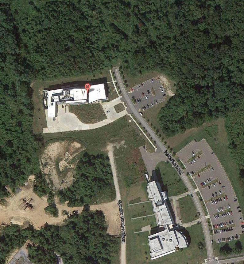
73
ELIZABETH KENNEDY LANDSCAPE ARCHITECT
5d. MEP/FP Engineering
The stated scope of work received from SBU indicated that existing infrastructure in the AEC Building were at capacity and were not to be considered for use for the Smart Grid Innovation Center (SGIC) Addition. A site visit to the existing facility, and subsequent discussions and observations with operations personnel allowed us to determine availability of use of the existing infrastructure. The proposed conceptual MEP descriptions included in this document take into account our findings.
The design strategy for the MEP systems is to provide an energy efficient infrastructure that can be utilized for the stated program and use of the new building as well adapt to different needs of potential energy incubator tenants. The infrastructure design will assist in meeting the requirements of LEED silver as a minimum.
Mechanical
The AEC building mechanical infrastructure was designed with no expandability. Although there are two chillers in the basement MER, the system is designed so that only one chiller operates at a time. During the day, the main chiller operates to provide chilled water for cooling of the building and is designed for the peak cooling load of the building. During off hours, the second chiller, which was designed to produce low temperature water, operates to make ice for use the following day to lower the demand requirements of the main chiller. It was reported that sufficient ice storage is not available to meet the needs during the summer months, hence the use of the main chiller.
The hot water boilers were similarly sized to meet the peak demands of heating of the building with no spare capacity for a future building.
The conceptual design intent of the SGIC building addition is to provide a modular design for the main components. This will allow for future expansion of the modular equipment to serve any future additions. At the present time, an economic evaluation is being done to determine the cost effectiveness of a screw chilled water chiller versus a modular scroll compressor system. In addition, an analysis if being performed comparing the use of modular hot water boilers generating 1800 F water versus the use of condensing type boilers which generate lower temperature water. Lower temperature water requires more GPM for heating, larger heating coils and therefore more construction costs.
74
Electrical
Although the stated scope of work for the project indicated that existing infrastructure in the AEC building was at capacity, a review of the incoming electric service and switchboard usage provided information indicating that there was sufficient capacity available to serve the electrical needs of the new SGIC Addition. Subsequently we provided two options for pricing considerations.
Emergency Power
Similar to existing electrical capacity above, two options for pricing considerations were provided. Centralized emergency panel shall be located in adjacent electrical closets to provide on an as needed basis emergency where requested or required by program and or room data sheets.
Fire Alarm System
The fire alarm system currently installed is expandable to accommodate the new building.
UPS
As noted above for the normal and emergency system it would appear the new buildings needs can be served by a local centralized UPS system.
Plumbing/Fire Protection
Visual analysis of the existing plumbing and fire protection infrastructure indicated that except for the fire pump, the existing infrastructure could not support the needs of the SGIC Addition.
The plumbing design is structured to meet the needs of the intended program.
The existing fire pump, while located at the farthest point from the new building, will be replaced with a pump designed to provide additional pressure needed to reach the most remote hydraulically calculated area to be sprinklered. The SGIC will be fully sprinklered, but will not have fire standpipes in the building.
75
JFK&M CONSULTING
5e. Acoustics, IT, AV & Security
Introduction and Summary
Shen Milsom & Wilke, LLC (SM&W) has prepared this report to summarize the Acoustical, Security (SC), IT Infrastructure, and Audiovisual (AV) design concepts for the new SUNY Stony Brook Smart Grid Innovation Center Addition. This report is based on the latest Concept Plan drawings.
It is requested that this report be shared with the design team, and to advise SM&W where design recommendations will not be possible and alternate recommendations need to be provided. Should you have any questions regarding this report please contact Andrew Davies, SM&W’s assigned Project Manager.
Acoustics
The initial section of the Acoustics report addresses the SGIC Wing portion of the project. The Dynamometer building area is addressed later in this section.
Structural
1. Mechanical Room Floor Slab (slab-on-grade)
The mechanical room will likely be slab-on-grade; dependent on the building scheme. The grade slab is recommended to be an independent pour with a perimeter isolation joint. This will help ensure minimal vibration and noise from equipment is transmitted via the floor-slab-path.
2. Mechanical Room Floor Slab (elevated slab)
Dependent on the scheme and layout an elevated mechanical room slab can be nominal 60 psf (3.5” normal weight concrete, NWC, on 3” metal deck, MD; total 5.5”) when housing air-handling units and pumps 15 HP or less.
3. Mechanical Room Ceiling/Roof
The roof slab under the cooling towers, assuming they are above mechanical space, can be nominal 50 psf.
4. Roof Slab at Strobic Fans
The roof slab under and nominally 15 feet away from the Strobic Fan footprint is to 75 psf (which is as noted in the Structural narrative as 4.5” NWC on 3” MD). This provides a stable base for direct mounting of Strobic fans and/or the intake plenum.
5. Basement Microscopy Room
Should a Microscopy room be provided in the
basement, it is to be a minimum 12” thick independent slab with an perimeter isolation joint. All footings (exterior and interior) within the area of the slab area are to be at least 12 inches below the bottom elevation of the independent slab.
Architectural
1. Adjacencies
a. Main Conference Room & Labs
Lab spaces adjacent to the Main Conference Room are separated by a double wall condition due to the building geometry. This will provide a high level of acoustic separation, but will not reduce vibrationinduced structure-borne sound transmission. This includes any type of impact on the floor, lab equipment operation, lab activities on benches, etc. Administrative control of adjacent activities is highly recommended. A “quiet” lab with minimal machinery and impact related activities should be avoided adjacent to the Main Conference Room.
b. Main Conference Room & Restroom
Restrooms are understood to be located remote of the Main Conference Room. Thus, there is no acoustic concern with sound transmission.
2. Partitions
a. Labs and Offices
The partition between labs and between offices is to be as follows:
• Insulated 2 layer drywall to structure: Single layer drywall each side of metal studs with full depth insulation between studs; erected to the structure above. All penetrations and terminations are to be acoustically sealed.
• This partition will provide a nominal Sound Transmission Class (STC) 40, dependent on stud gauge and spacing. This degree of acoustic separation will provide “normal” privacy where voices will be audible in the adjacent space, but context of conversation will be minimal; assuming normal voice levels. This description does not consider eavesdropping, raised voices, speakerphones, or consideration for “loud” research equipment. A nominal STC 40 acoustic separation between standard offices and research labs is typically sufficient. The user groups should comment on the described acoustic separation and comment on whether appropriate. There are no acoustic guidelines or criteria outlined in the 12/19/2014 “Campus Standards Manual”.
b. Main Conference Room
The partition surrounding the Main Conference Room is to be as follows:
76
• Insulated 4 layer drywall to structure: Double layer drywall each side of metal studs with full depth insulation between studs; erected to the structure above. All penetrations and terminations are to be acoustically sealed.
• A nominal STC 50 will be provided with this partition. This provides a high level of privacy in that normal voices are typically not audible, while raised voice and amplified audio systems are audible but mostly unintelligible. . A nominal STC 50 acoustic separation for Main Conference Room solid partitions is an industry standard approach.
c. Partition Termination at Curtainwall
Specific details will have to be developed at the partition closure to the curtainwall. This includes at the sill, window mullion and head condition. Acoustic seals, caulking and insulation packing will be detailed to provide an appropriate acoustic seal for all the perimeter termination conditions.
d. Partition Details
Specific acoustic seal details and junction box locations will be necessary to maximize the acoustic separation. These details will be coordinated as the project design progresses.
3. Doors
a. Office Doors
The office front system doors are to have the manufacturer’s upgraded acoustical seals provided with their package; including a drop seal if available.
b. Main Conference Room Doors
The Main Conference Room doors, including those to the Food Service Room are to be provided with full perimeter acoustic seals. The type and detail will have to be coordinated with aesthetics. Millwork can potentially be constructed around relatively standard acoustic seals, and automatic drop seals can be mortised into wood doors. Ideally, the center of double doors is provide with an off-set rabbeted-edge seal while incorporating a door-closer coordinator.
• A counter pass-thru approach between the Conference Room and Food Service Room was discussed (with sliding doors on each side of the counter). This is very convenient, but provides very little acoustic separation between the spaces. This approach is discouraged; especially if the Food Service Room will be used as a separate Break Room as well.
4. Finishes
a. Main Conference Room Finishes
The acoustic environment within the Main Conference Room must be sound absorptive in order to enhance
speech intelligibility and maximize the performance of the audio system. To this end, the following is to be provided within the Main Conference Room:
• Sound absorptive ceiling throughout the room, with a drywall perimeter possible.
- Acoustic panel/tile; similar to Armstrong “Optima” fiberglass panels
- Perforated or slotted materials with insulation above
- Micro-perforated wood or plastic film with insulation above
- Nominal Noise Reduction Coefficient (NRC) 0.85 or higher
• Sound absorptive wall finishes
- Fabric wrapped 1” thick fiberglass panels
- Perforated or slotted materials with insulation above
- Micro-perforated wood or plastic film with insulation above
- Nominal Noise Reduction Coefficient (NRC) 0.85 or higher on approximately 50% of the wall surface; though strategically placed based on further room layout and AV system review.
b. Floors surrounding & above the Main Conference Room
Floor finishes around and above the Main Conference Room would ideally be carpeted in order to reduce impact and rolling cart noise transmission to the Room. Hard surfaced floors allow footfall impact noise transmission to the Room and potentially distract meeting proceedings.
• Hard floor finishes adjacent and above the Main Conference Room are to have an resilient underlayment in order to reduce footfall and rolling cart noise transmission. The resilient underlayment is to be similar to Pliteq, “GenieMat RST10” (3/8” thick). The final cross-section will have to be coordinated with the floor vendor. It is highly likely that a cement board substrate will be required between the underlayment and hard floor finish (vinyl flooring is considered a hard floor finish). The underlayment and substrate could occupy 1+/- inches of elevation. This must be considered in the floor elevations and transitions. Coordination the flooring vendor is recommended as soon as possible in order to obtain an approved crosssection and determine the extra height/elevation.
Mechanical
The following are the general noise & vibration control guidelines and recommendations for the project. Specific performance and requirements will be coordinated with the Mechanical Engineer as the design progresses.
77
SHEN MILSOM & WILKE
1. Chiller
Provide a “quiet” electrical centrifugal or mag-lift bearing chiller mounted on 1” deflection spring mounts. Screw or scroll compressor chillers should be avoided.
2. Cooling Tower
Provide a “low-noise” induced-draft propeller fan or forced-draft centrifugal fan cooling tower. This is to be considered for pricing and layout at this point. Specific cooling tower type and performance will be reviewed and coordinated as the project design progresses.
3. Condenser and Chilled Water Pumps
Pumps are to be mounted on spring-supported concrete inertia pads for vibration isolation.
4. Mechanical Piping
All mechanical piping within the mechanical room, but not less than 50 feet from rotating equipment to be resiliently hung or supported.
• All rooftop mechanical piping is to be resiliently hung or supported.
5. Main Air-Handling Units
Main air-handling units are to have sound attenuators on the intake and discharge side of the unit. Ideally, the attenuators would be 3-5 foot and including internal to the units. Otherwise, attenuators within the ductwork will require specific duct layouts and lowered air velocities in order to control pressure drop.
• In-duct attenuators would be 5-7 feet long and require straight duct length in and out; or semi-custom moderately-low velocity elbow attenuators.
6. Main Distribution Duct
Main distribution duct is to be sized for a nominal maximum of 2000 fpm, and potentially lower dependent on exposure and duct layouts.
• All medium pressure duct that is exposed will require a distinct air-seal effort to ensure minimal air “hissing” type noises.
7. Pressure Reducing Devices (VAV & CV Boxes)
Pressure reducing boxes are to be selected based on radiated noise limits, and assuming an exposed condition within the labs, that limit will be relatively low (in the range of 60 dB in the 3rd octave band, 250 Hz, at the envision inlet or differential pressure). Thus, boxes will likely be up-sized from “normal” selections, and/or split into 2 smaller boxes instead of 1 larger box.
• There are to be no pressure reducing boxes above the Main Conference Room.
8. Low-Pressure Ductwork (VAV & CV Box Discharge Duct)
• Pressure reducing box discharge noise will be controlled by in-duct discharge attenuators. Minimum 3 foot third party attenuators, such as those from Industrial Acoustics Company (IAC), are to be provided on the discharge of all pressure reducing boxes (VAV & CV boxes). Attenuators with plastic film-encased insulation with acoustic stand-offs are to be considered.
• Attenuators are to be provided on the room-side of exhaust and fume hood air-control valves. General exhaust can be standard insulation type attenuators, while fume-hood attenuators are typically round nomedia type with metal matching the ductwork type.
9. Strobic Fans & Exhaust Plenum/Duct Strobic fans are to be selected as the largest, lowest speed option that complies with mechanical and fume ejection requirements. Smaller, high-speed Strobic fans can be excessively “loud”.
• Nozzle attenuators are to be provided for the Strobic fans; to help reduce noise emissions to the campus and community.
• Attenuators are to be considered within the inlet ductwork to the common exhaust (fan intake) plenum, and on the induced air path for the intake plenum. The ductwork and plenum layout must consider these elements. Main exhaust ductwork above occupied space, if applicable, should consider an independent stud/ insulation/drywall architectural enclosure to help reduce duct radiated (breakout) noise to the occupied space.
• Strobic fans are to be mounted on neoprene pad isolation with distinct resilient bolting details.
Dynamometer Labs Addition
The following acoustic considerations, for acoustic separation of Dynamometer Room equipment noise, are to be applied to the Dynamometer addition.
• Locate the Dynamometer rooms away from the adjacent high-bay lab (position the Control Rooms adjacent to the high-bay lab). This is to help reduce engine noise transmission to the adjacent lab.
• Provide an independent slab-on-grade for the Dynamometer rooms with a full perimeter isolation joint.
• Provide a two (2) independent normal weight concrete block walls straddling the independent slab joint between the Dynamometer Room and adjacent Control Room.
• Provide an expansion/control joint in the exterior wall and roof between the Dynamometer and Control Rooms.
• Windows between the Dynamometer room and
78
IT, AV & SECURITY (cont’d)
ACOUSTICS,
Control Room are to be heavy-duty acoustical assemblies such as those provided by Industrial Acoustics Company (IAC); two (2) independent frames with thick laminated glass within.
• Doors to the Dynamometer room are to be heavy-duty 6” thick acoustic assemblies (STC 63+/-), such as those provided by IAC. Blast resistance may also want to be considered for these doors.
Information Technology Infrastructure (ITI)
The technology design is for a 20,000 GSF addition to the Advanced Energy Center (AEC) Building at the Stony Book Research and Development Park. This new addition is specifically designed to support research and development in Smart Grid Technology. SM&W scope of work includes the design, coordination and specification of pathways and spaces for a complete structured cabling system. All horizontal cabling, backbone cabling, termination and testing shall be the responsibility of Stony Brook University. All equipment racks, connecting hardware and pathways in the Telecom Rooms shall be the responsibility of Stony Brook University.
1. Telecom Room (TR)
A new TR is recommended on the first level of the proposed addition. The TR will house switches, backbone cabling and station cabling. All of the above shall be the responsibility of Stony Brook University.
• The recommended environmental limits for the telecommunications rooms are 64-75 degrees Fahrenheit and 30-55 percent relative humidity, non-condensing.
• HVAC systems serving the TR shall be capable of 24-hours-a-day, 7-days-a-week operation.
• Lighting levels within the TR shall be a minimum 50 foot candles maintained at 36-inches AFF.
• Power circuits for all telecommunications equipment located within the TR should be fed from an electrical panel dedicated to these loads and located within the room. Telecommunications system loads would be best served from a UPS power source.
2. Pathways
• Telecom riser conduits shall be located in the Telecom room. The TR shall contain a minimum of (4) 4” conduit sleeves in slab for backbone, horizontal, CATV and grounding cables. Pathways shall consist of cable trays, conduits and j-hooks per the latest BICSI standards.
3. Telecommunications Cabling System
All backbone and horizontal cabling shall be installed by Stony Brook University. The telecommunications
cabling system shall be designed to conform to the requirements of EIA/TIA 568C, The Commercial Building Telecommunications Cabling Standard.
• SMW shall design the pathway infrastructure per the latest BICSI standards and shall support wireless LAN connectivity.
• Horizontal Cabling: 90 meters from the work area outlet to the termination equipment in the TR.
• Backbone Cabling: 500 meters from the MDF room termination equipment to the TR termination equipment. Telecommunications room shall have 24-strands 50/125u multi-mode optical fiber cable and a 50-pair UTP cable (or as specified by SBU) from the MDF Room.
4. Workstation Cable
The telecommunications cabling system shall be designed to conform to the requirements of EIA/TIA 568C, The Commercial Building Telecommunications Cabling Standard.
5. Uniform Telecommunications Grounding System
A uniform telecommunications grounding and bonding system shall be provided in accordance with EIA/ TIA-607-A, Commercial Building Grounding (Earthing) and Bonding Requirements for Telecommunications. This system shall be designed in conjunction with the electrical power grounding system.
6. Pathways, Space, and Media Identification
An identification system shall be developed to uniquely identify each equipment rack, pathway segment, equipment room, TR, rack, patch panel, and cable installed in the building.
7. Wireless Technology
Wireless Access Points (WAP) will be shown on the Telecom drawings for reference. The WAP’s locations will be cabled back to the TR utilizing the provided pathways. Cabling and antenna shall be the responsibility of Stony Brook University
Audiovisual Systems Infrastructure
The information supplied here will be combined with further program report developments and budget estimates in order to facilitate decisions about audiovisual capabilities. These decisions will help finalize architectural and infrastructure decisions, as well as validate current assumptions about cost planning. The input from Stony Brook personnel will play an important role in shaping the development of these spaces.
79
SHEN MILSOM & WILKE
SM&W scope of work shall include the design, coordination and specification of pathways and spaces for audiovisual systems. All horizontal cabling, backbone cabling, termination and testing shall be the responsibility of Stony Brook University. All equipment racks, video switching, audio amplification, and associated devices shall be the responsibility of Stony Brook University.
1. Existing Conditions
The existing conditions within the facility are only minimally relevant to the current AV design. The existing conference room was outfitted with a projector, control touch screen, a table laptop input and a room PC. From the existing conditions and subsequent client interviews we can confer that dedicated room PCs are required in each of the relevant AV spaces and that all AV equipment is located within the applicable rooms themselves. One significant item that will impact the existing spaces is the client’s request to outfit each of the existing spaces with room scheduling panels as part of the new work. This should be given special consideration especially for the electrical scope.
2. AV Spaces
The following are spaces which will support AV systems, and the types of support provided by the infrastructure. As a general note, all AV equipment shall be specified at a leter date during the DD and CD design phases.
a. General
• Room scheduling panels shall be located at all conference rooms including existing rooms.
• All devices shall integrate with a web based
• AV control and asset management system.
b. Smart Grid Modeling & SIM Room
• Infrastructure shall be provided for a multi display flat panel LCD or LED videowall
• The determination to outfit these displays day 1 or at a later date shall be made during the DD or CD phase of the project.
c. Small Conference Room
• A flat panel monitor is recommended due to the small size of the space.
• Presentation capabilities only
• Wireless BYOD presentation capability
• Should incorporate a room PC (possibly one embedded in the display)
• Simplified wall mounted control panel
• Integrated lighting control if available
• Equipment can be mounted in a credenza or hidden behind the display or underneath the table
d. Atrium/Student Poster Display Area
• Shall serve as the pre-function space for the large conference room
• Infrastructure for a signage display connected to a PC at front desk, Campus TV and a local connection within the atrium
• Program audio and background audio from surface mounted speakers
e. Main Conference Room
• Equipment racks shall be located within a credenza or in a separate closet to house the AV equipment for this room and the atrium.
• A projection screen and projector is recommended to achieve the large image size required for adequate viewing of the audience.
• Shall be a flexible use space with movable furniture
• Shall incorporate audio conferencing via installed audio systems and VoIP system (Cisco)
• Shall incorporate (1) camera for use with pc based soft codecs like webex or skype.
• A wireless conferencing microphone system shall be used
• Wireless BYOD presentation capability
• High quality program audio including low frequency reproduction
• A countdown timer at the podium and the back of the room
• Podium at the front of the room, may be a standard classroom type(to be determined later)
• Campus TV may be provided
• Provide USB ports at laptop input points for flash drive, PowerPoint slide advancer dongle, and HID input to room PC
3. Design Approach
All elements of the audiovisual systems must allow both current applied standards-oriented technologies, as well as upcoming future technologies. This design approach includes the audiovisual capabilities consistent with traditional requirements outlined above, while providing a flexible infrastructure capable of expansion and upgrades when incorporating future technologies.
In order to accomplish this, the infrastructure will contain conduit sized to allow for additional cabling as requirements change. In addition, we will focus on coordinated network connectivity for devices such as flat panel displays and projectors, as well as at equipment rack locations, as we incorporate the trend of AV systems becoming tightly integrated into the network topology. This approach will allow for compatibility with today’s audiovisual equipment, both standard and high definition, while allowing for future equipment that will require greater bandwidth. In addition, these efforts will incorporate the ideals of student involvement and collaboration capability.
80
(cont’d)
ACOUSTICS, IT, AV & SECURITY
4. Applicable Codes, Standards and Regulations
The following standards will be followed when designing the audiovisual systems infrastructure.
a. Existing SUCF and SBU Standards
b. EIA/TIA Standards
b. ANSI/INFOCOMM 10-2013, Audiovisual Systems Performance Verification
d. Other applicable ANSI/InfoComm Standards
Security Systems Infrastructure
The existing access control system employed on campus is a Lenel access control system. The system is used primarily for access control functions utilizing smart card technology. There is also an existing Video Surveillance System (VSS) on campus. The system is used primarily for surveillance, mainly for investigative purposes, at designated areas throughout the campus. The University shall provide all security equipment, cabling to devices, equipment racks, and terminations. The University shall also provide Lenel software upgrades and/or VSS upgrades as necessary.
The scope of work for this project is to provide the security intent design, including infrastructure, back box & conduit. The tie-in back to existing head end, or the expansion/ upgrade of head end equipment to accommodate these new security devices would be the responsibility of SBM.
During the following Schematic Design phase, the following tasks should be completed:
• In-house resources and design consultants shall work in conjunction on the initial design concepts and develop an outline of the requirements
• Review architectural floors plans and the impact of security systems and infrastructure on the design on the new Smart Grid Innovation Center space and the physical layouts
• Gain further understanding of the operation security requirements for the Smart Grid Innovation Center in order to establish device locations that best complement those needs and provide better overall efficiency in the existing and planned operations
• Coordinate high-level security programming for space requirements and infrastructure
• Develop a Schematic Design Report that outlines the security technology applications
1. Electronic Access Control
A computer based card access system is popular because it expedites the control function. The system electronically checks a cardholder’s authorization to enter a restricted area, grants or denies access, records the event, and
maintains a computer history of everyone that entered. Electronic access controls systems help minimize the number of security personnel needed for the access control task. A card access system is normally used to control access from unsecure (public) areas to secure (non-public) areas. This transition between the two areas establishes the secure perimeter. Security personnel are used at a gateway points to oversee the operation while card readers are used to verify a person’s identity and access privileges. In open spaces such as lobbies where physical doors are not feasible, card reader controlled turnstiles or optical portals may be used to establish a virtual perimeter.
Examples where card readers or other electronic access control devices should be used in theSGIC
• Incubator spaces
• Labs and Simulation spaces
• Storage areas
• Mechanical rooms
• Electrical Mezzanine areas
• Control rooms
• Dynometer rooms
• Exterior Entrances
2. Security Alarms
Building perimeter openings and other restricted facility space should be equipped with security alarm sensors and monitored by a 24-hour operation. As with access control, SM&W will indicate the required infrastructure to support these devices.
Common Alarm Points:
• Door Position Switches: Monitors intrusion or unauthorized propping of door. Locations:
- Perimeter Doors
- Critical Utility Areas
- Electronic Access Control Doors
- Stairway Doors
- Roof Access
- Any Area Defined by the University
• Intrusion Sensors: Motion detectors, glass break, and a variety of other security sensors that monitors intrusions. Locations:
- Special Storage Areas
- Accessible Window Fronts
- Operable Utility Openings
• Panic/Duress/Medical Emergency Alarms – These locations are to be defined by the University. Most common locations are at the exterior entry/exact points, restrooms, and cafeterias. Locations:
- Restrooms
- Atrium/Lobby area
- Any Area Defined by the University
81
SHEN MILSOM & WILKE
3. Video Surveillance
Video Surveillance is widely used as an effective application for security to deter, detect, and apprehend. With this concept, security is applied to deter an individual from committing an unlawful act. Failing that, speedy detection of the act should occur. Following detection, the system should contribute to apprehending the perpetrator. SM&W will identify and provide the proper infrastructure to support locations that will have a camera.
Video Surveillance should be utilized in the following locations:
• Building Perimeter
• Pedestrian Entry and Exits
• Lobbies
• Service Corridors
• Reception Waiting Areas
• Student Gathering Spaces & Corridors
• Any Area Defined by the University
4. Security Control Spaces
These areas serve as the point of demarcation for the control panels, power supplies, and signal transmission equipment for the SMS/VMS. Our design shall allocate space in each telecom room for access control panels, power supplies, servers and other associated equipment used to serve the security devices/cameras on a given floor.
5. Security System Riser
The security system shall utilize a riser system to transmit and receive signals as well as carry power to field devices. The security system shares riser space with the IT infrastructure. The security system riser and infrastructure design will be based on the requirements and specifications of the University’s Access Control and Video Surveillance systems standards.
6. Security Wiring and Conduit
Pathway routes will require coordination with other building services (electrical, mechanical, plumbing, etc.) to assure proper clearances and accessibility. Security cabling should never be exposed and should be contained in protective conduit wherever cable is accessible to vandalism, accidental damage, or where it traverses any unsecure space. The horizontal cable distribution pathways shall be sized and planned to accommodate cable changes, as well as minimize occupant disruption when such pathways and spaces are accessed. Security conduit requirements at all in-wall installations generally consist of ¾-inch conduit to accommodate security wiring, connected to the respective junction box.
82
ACOUSTICS, IT, AV & SECURITY (cont’d)
06. Cost Estimation
A cost estimation exercise was developed with the proposed conceptual layout (base scheme) and several options as described in the previous chapters. (refer to Appendix G for full breakdown)
(*) Includes Dynamometer Labs
83
BASE SCHEME SGIC — Option 1 SGIC — Option 2 SGIC — Option 3 Smart Grid Innovation Center Wing Dynamometer Labs Service Elevator Core & Shell Basement Full Basement w/ Program Construction Cost $17,702,816 $2,564,652 adds to base $635,387 adds to base $3,177,990 adds to base $6,630,525 GSF 21,650 GSF 3,505 GSF 4,509 GSF 8,796 GSF $/SF 817.68 731.71 704.89 753.85 TOTALS (contruction cost) $20,267,468* $20,902,855* $23,445,458* $26,897,993*
07. Schedule
Schedule
The schedule depicted below is treated as an estimated outline which could be further narrowed and defined once the commencement of Phase 2 gets established.
To this day it is not certain when the funds will be available to proceed with reminder of the project design and construction.
January2015
PHASE 1
Programming
Conceptual Design
Design
January2016
January2017
January2018
January2019
PHASE 2*
Design Development
Estimate Review
Construction Documents
**
Phase 2 - estimate assumes award and starting with the design development phase after summer 2015. Includes Make ready, procurement, construction and lab equipment installation.
Move-in
84
Construction
Schematic
June2015 June2016 June2017 June2018
**
*
08. Conclusion
Conclusion
The programming strategy and conceptual design that evolved through the processes described in this program follow the design strategy established by the Master Plan developed for the Research and Development Campus, upon which the Addition stands, and achieves the goals articulated by the program needs and the existing building’s concerns.
Additions to the existing building to accommodate the added program are developed to support the overall character of the existing building, and make it read as an homogeneous complex.
The Addition will serve the Advanced Energy Center with a lab research module similar to succesful modules in the existing building. It will mix lab research and incubator tenant spaces, and prove a new functional administrative area to serve the building as a whole, supporting the existing administration area.
The Programming and Plan layouts for the Additions will provide Stony Brook University with a state-of-the-art academic building, equipped with high quality research laboratories and incubator spaces, as well as a Main Conference Room to fulfill the needs of the Advanced Energy Center.
The SGIC Addition is the next logical step on the development of the Research and Development Campus. The Addition will support academic excellence at AEC and SBU.
This programming effort provides a road map for the expansion to the Advanced Energy Center to achieve the goals outlined in this report and by the University.
85
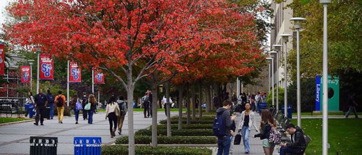
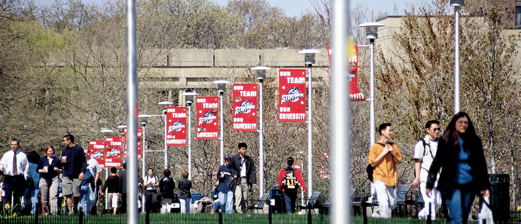

86
Design Team
Architect
Davis Brody Bond, LLP
Architects and Planners
One New York Plaza, Suite 4200, New York, NY 10004
Tel. (212) 633-4700
www.davisbrody.com
Structural Engineers
LERA, Leslie E. Robertson Associates
40 Wall Street, 23rd Floor
New York, NY 10005
Tel. (212) 750-9000
www.lera.com
MEP/FP Engineers
Jacob Feinberg Katz & Michaeli
Consulting Group, LLC
JFK&M Consulting Group
134 West 37th Street, New York, NY 10018
Tel. (212) 792-8700
www.jfkmcg.com
Civil
Hirani Group
421 Seventh Ave., RM 808
New York, NY 10001
Tel. (516) 248-1010
www.hiranigroup.com
Landscape Architect
Elizabeth Kennedy Landscape Architect, PLLC
Brooklyn Navy Yard Building 275 - 202
63 Flushing Avenue Unit 264
Brooklyn, NY 11205
Tel. (718) 596-8837
www.eklastudio.com
Telecommunications, Security, Audiovisual & Acoustical Consultants
Shen Milsom Wilke (SM&W)
417 Fifth Avenue, New York, NY 10016
Tel. (212) 725-6800
www.smwllc.com
Sustainability/Environmental Consultant
Atelier Ten
45 East 20th Street, 4th Floor
New York, NY 10003
Tel. (212) 254-4500
www.atelierten.com
Cost Estimating
V.J. Associates Inc. of Suffolk
100 Duffy Avenue, Suite 301
Hicksville, NY 11801
Tel. (516) 932-1010
www.vjassociates.com
87

www.davisbrody.com
Davis Brody Bond, LLP Architects and Planners One New York Plaza, Suite 4200 New York, NY 10004


 Research & Development Campus: 2017 (from Beyer Blinder Belle Master Plan)


