22 minute read
Design economics of infield bridges for offshore wind farms


by Bob L Y Cheung, Bob Cheung Offshore Consultants
The article will put forward suggestions for cost-effective outcomes.
INTRODUCTION
At the Glasgow 2021 UN Climate Change Conference (COP26), hosted by the UK and co-chaired by International Energy Agency (IEA), IEA reported that, as of 2021, 44 countries and the EU have pledged to achieve the net-zero target by 2050. However, it also pointed out that, even with all the pledges fully delivered, the global net-zero initiatives may not meet the 2050 target for various reasons [1]. Among major developing countries, China has pledged to reach net-zero by 2060, and India has set the target at 2070. Due to huge financial costs and the associated industrial transformation required, these two large economies may find it difficult to reach the desired targets. Nowadays, every offshore wind farm (OWF) project is a multi-billion-dollar venture, and few countries and mega-companies in the world can afford the high development costs [2]. Recent power shortages around the world showed that fossil fuels may continue to play a major role in many countries after 2050, if the energy transition movement is not quickened. The real problem is not technical, instead, it is the lack of international financial support for many energy transition projects around the world. To assist developing countries in energy transition, many rich nations have pledged billions of dollars every year to help, but it is still a plan with little action. The best way to accelerate the transition is to make it much more affordable for particpants in the developing world. The objective of the three articles on design economics (inclusive of this article), published in ‘The Singapore Engineer’, is to propose an alternative approach to develop offshore wind farms, as a small part of the global net-zero action plans, using old and/or makeshift equipment and avoiding subsea activities as much as possible. In essence, the developing world should not follow the European development method which involves the use of new-build jack-up turbine installation vessels and new-build cable-lay vessels. The method is too costly for developing countries. The alternative approach is economical and may also create many new business opportunities and a lot of new jobs in many developing countries. In our view, offshore wind energy is not the most cost-effective solution for energy transition and is likely to be overshadowed by wave energy, when the application of wave energy technology has reached the production stage. Ideally, the best transition solution is to have an integrated offshore energy farm (OEF) which is capable of producing energy from all three sources – wind, wave and solar. This could be the truly economical and achievable target in the future. We published an article on Multi-Purpose Offshore Wind Farms [3] in the March 2021 Issue of ‘The Singapore Engineer’, where we proposed to bridge-link all the pile-supported wind turbines in a farm. The intention is to run cheaper surface array cables on the bridge decks instead of burying expensive subsea array cables below the seafloor. The proposal can reduce project cost from operation, maintenance and decommissioning. To partially offset the high cost of building the infield bridges, the bridge decks can be turned into a solar farm to generate income. As a bonus, the bridge-support structures can provide lots of locations to attach wave energy converters in the future. We published another article, this time, on Trimaran Wind Turbine Installation cum Decommissioning Vessels [4], in the September 2021 Issue of ‘The Singapore Engineer’. The article deals with the replacement of jack-up wind turbine installation vessels with used and cheap barges. The makeshift trimaran vessel can also be used for turbine decommissioning. The author also suggested that the single, large diameter wind turbine tower, usually weighing more than 800 tons for bigger turbines, should be replaced by a lighter and stronger tubular space truss. Under extreme weather conditions, a truss tower offers better ‘overload performance’ than a single, vertical tubular cantilever. Large tubular turbine towers do get damaged in extreme storm conditions [5]. However, the proposed multi-purpose offshore wind farm raises one important question. How expensive is the infield bridge system? This article will address the design aspects of the issue. We will discuss how best to design, fabricate and install the bridge-support structures and the infield bridges. Due to a lack of reliable data, the total financial cost cannot be properly discussed in this article because it is inter-related to the costs relating to the three renewable sources of energy.
DISCUSSION OF PROJECT EXECUTION STRATEGY AND HIGH COST AREAS
In engineering design, the designed product should reflect how the job is bid and executed. In the design
example [3], [4], wind turbine spacing is set at 3850 ft. This separation will be sub-divided into six segments of about 600 ft each. For a wind farm with 100 turbines, there will be a few hundred infield bridges and a few hundred internal bridge-support structures. To execute this huge construction project, we have to invite many qualified fabricators to bid for the jobs. A bridge length of 600 ft is chosen to suit many yards in the region. By having a large pool of bidders, the offered prices should be competitive. However, bidders submitting alternative proposals should also be allowed. In engineering, there are many ways to do the same job, and some bidders may offer cheaper alternatives. The work scope calls for complete fabrication of all the structures in the yards prior to loadout. Transportation, installation and commissioning will be under separate contracts. Installing a 600 ft long bridge is still within the capability of many qualified installation contractors, without the need to build new vessels and/or special handling equipment. All installation bidders will be requested to bid on a lump-sum basis. They have to factor in all the risks in their proposals. In times of arbitration, it is better to have a lumpsum contract. The selected project derrick barges should each have a lift capacity greater than 2000 tons. This bidding strategy is both realistic and cost-effective but requires a large project management team (PMT) to coordinate the activities of all the suppliers, contractors and inspectors, from a few countries. The PMT cost could be in the range of millions of dollars. It is obvious that the infield bridges and the internal bridge-support structures will be a major cost component of a wind farm project. To reduce project cost, three high-cost impact areas must be studied.
Wind farm site selection and field layout for the multi-purpose wind farm
There are many important factors related to site selection and field layout, but we will consider only OWF infield bridges installation-related issues. In shallow water offshore construction, derrick barge relocation is time-consuming and non-productive. In a typical oil field development project, platforms are usually not far apart. Hence, barge relocation is not a big issue, requiring just extra hours of barge time. For a long duration wind farm installation project, as in our example, the accumulated barge relocation time for all the wind turbines could be more than 100 days. For the multi-purpose offshore wind farm, the total relocation time is much longer. The unproductive cost is huge and must be reduced. In offshore pipe-lay operations, to achieve high lay-rates, the lay-barge must move forward on an almost continuous basis, in order to match the speed of welding of the pipejoints. A higher lay-rate implies higher profit. For the multi-purpose OWF project, the installation speed is a major cost component. One should make sure that the layout of all the turbine structures is installation-friendly, and the selected site should not create major problems for pile driving. The field layout is site-specific and it is not possible to cover this topic at length. As a comparison, the time needed to relocate a jack-up installation vessel is much longer, as there are many safety procedures to go through before the jack-up rig can be set up onsite. The use of jack-up vessels is excluded in these articles on multi-purpose wind farms.
Bridge-support structures
In the oil & gas industry, a traditional bridge-support structure is usually a tripod or a simple four-pile jacket. In the example of the wind farm, this traditional design is still applicable. But the design concept must be modified to cut cost.
Long span bridges
A 600 ft long infield bridge is considered a long span bridge. There are many outstanding long span bridges in the world, and the common features are their low weight and the fact that they are usually site-assembled. Site-assembly is not cost-effective and is impractical for building infield bridges. To house a few thousand workers offshore, for years, to carryout site construction, is not a feasible solution. Offshore hourly labour rates are much higher than onshore rates. Therefore, the contracts call for all bridges to be fabricated in the yards prior to loadout. A robust design is needed to enable transportation and installation to be done without many temporary bracing supports. It is a time-consuming operation to remove tie-down braces and restore the bridge to the original condition, as is usually dictated by the owners. Maintenance, repair and decommissioning activities must be made easy and without relying on expensive jack-up vessels. These requirements call for a different thinking in the design.
DESIGN OF BRIDGE-SUPPORT STRUCTURES
Design considerations
The simplest structure is a portal frame (sway frame) which does not require frequent underwater inspections. Basically, a portal frame has four piles supporting a deck. The deck serves as an intermediate landing platform for the infield bridges. However, a portal frame is not buildable offshore, and there are major installation and decommissioning problems with regard to the structure. Pile driving is a routine offshore operation, but keeping all four piles in the correct positions and orientations, after driving, is problematic, especially if the piles are set 40 ft to 70 ft apart. To pre-install the piles using a subsea template will change the whole installation concept and possibly double the cost due to doubling of derrick-barge-days in the project. To build the whole portal frame onshore and install it in one piece is a difficult operation, without lots of bracing members. The leg length is 170 ft, and it will be difficult to stab the pile into the leg for driving using a small derrick barge.
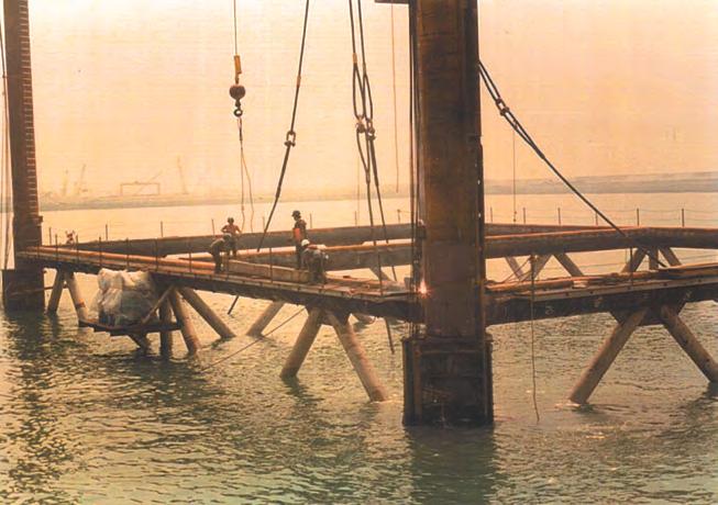
In addition, this option cannot provide the required flexibility to deal with different site conditions and installation errors. A transition piece is a must. A piling frame is a better choice to assist pile driving and deck mating operations, and the piling frame will remain as part of the permanent structure. A feasible design leads to a modified portal-frame/jacket structure which can provide a stable platform for pile driving. The traditional pile-inleg concept is better than the skirt pile, because it is a simple design with a direct load-path. In past piling projects, a piling frame was used to drive over 1000 external tubular piles in less than four months. To speed up the project schedule, both steam and vibratory hammers were deployed, depending on the soil conditions (Figures 1, 2 and 3). All installation activities were discussed and accepted by the owner and the certification authority, beforehand. A similar approach should be followed to ensure the project is fully covered. Based on past experience, assuming no pile-splicing, all four piles can be batch-driven and the deck can be set in less than 48 hours. However, a simple transition-piece design is required to correct all the installation errors and out-of-level issues.
Fabrication, loadout and transportation
In the proposed design (Figure 4), the portal-jacket has few members and few tube-to-tube connections, so fabrication can be done in seven to eight weeks. For the deck, it is a simple design. Since the bridge reactions go almost directly into the deck legs and the piles, all deck beams and braces should be small sized, and the fabrication should be simple. The tubulars are thin-walled, even at the joint-cans, which make welding easy and without special procedures. All large diameter tubulars can be rolled in Singapore or in nearby yards in Asia. The standard fabrication time should be about 10 hours per ton. Loadout can be done using multiwheel transporters or dollies, which are standard equipment in many local yards. Skid-loadout needs more preparation work and costs more. For transportation, a few upended portal-jackets and decks can be placed on a material barge and the piles can be transported on a separate material barge in a three- or four-tier tie-down arrangement, similar to the transportation of line pipes. However, the jackets must be checked for hook clearance using the project derrick barges.
Installation and decommissioning
The proposed bridge-support deck is 60 ft x 90 ft, and the Top of Jacket (TOJ) is 40 ft x 70 ft (Figure 4). Qualified installation contractors should already have many standard installation procedures in-house, and further explanation is not needed. However, these documents must be approved by the client and the certification authority beforehand. For decommissioning, we can cutoff all the grouted legs at mudline, then lift up the structure in one piece. The pile cutting tool is readily available in the market.
Figure 1: Piling frame.
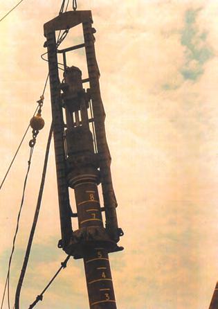
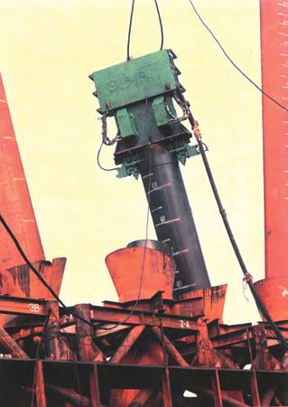
Figure 2: Steam hammer. Figure 3: Vibratory hammer.
DESIGN OF INFIELD BRIDGES Design considerations
In the oil & gas industry, an infield bridge between two platforms is usually about 100 ft to 200 ft long.
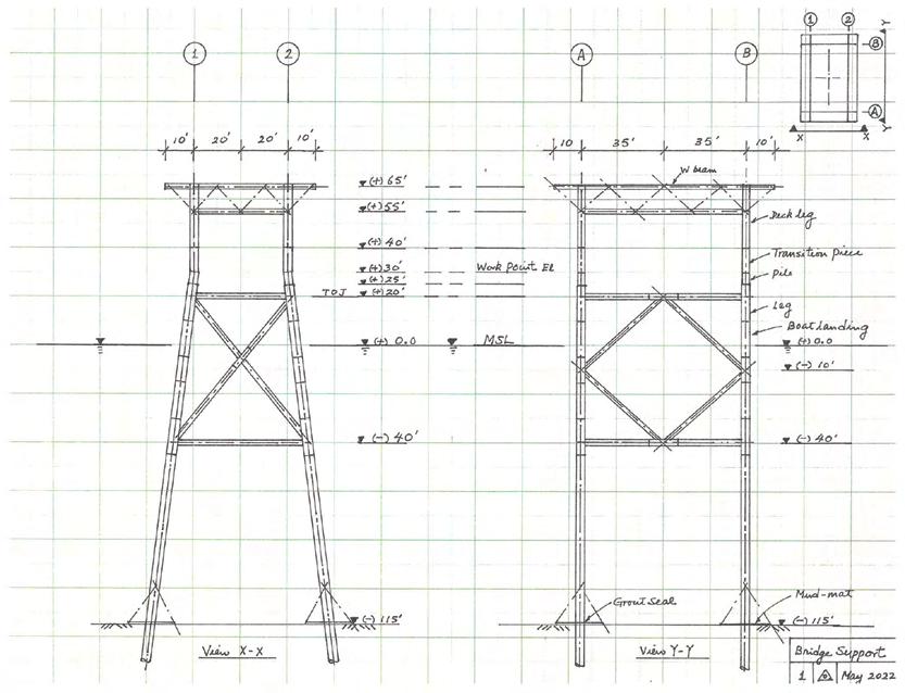
Figure 4: Bridge support structure.
For safety and/or based on other process requirements, in few large oil field developments, the bridge can be as long as 400 ft, if it goes from a production platform to a flare tower jacket or to a living quarters platform or to another process platform. In Southeast Asia, the usual bridge design fulfils the following requirements: • The bridge is designed for the simply supported condition. The relative displacements, at both ends, can be large, due to independent excursions of the two supporting structures. • The bridge design is robust, to handle loadout, transportation and lifting forces. • The bridge design is suitable for single-lift installation using one derrick barge, for economic reasons. If the bridge is too heavy or too long, intermediate bridge support platforms are introduced and the bridge is cut into two pieces. For a typical offshore installation campaign in Southeast Asia, the installation contractor will usually mobilise one derrick barge to perform all the lifts and the campaign duration is usually less than 30 days for a multi-platform field. For an offshore wind farm, the whole development can last for a few years, and we have to optimise every operation to cut costs. Therefore, the design requirements for the infield bridges must be expanded to cover more conditions. • The bridge design must be simple enough to encourage more qualified local fabricators to bid.
The intention is to solicit more competitive prices. A complicated design will cost more to fabricate and with no real advantages.
Simple, direct load-path design will always be the cheapest. • The bridge length must be selected to suit many local fabrication yards. • The bridge rise should be limited to about 100 ft, as large cranes are not common in local yards.
Big crane rental is prohibitively expensive due to difficulties in moving a big crane on the roads.
It must be dismantled, reassembled on-site and load-tested before using. For a simple, not-tooheavy lifting job in Singapore, the rental cost could be few hundred thousand dollars. Big crane rental from Europe will cost a lot more. • The bridge must be almost fully fabricated in the yard prior to loadout. Offshore assembly must be restricted to commissioning items. • The bridge design must be robust, so temporary bracing structures are seldom needed during loadout, transportation and lifting. However, a large weather window must be maintained. • The bridge must be designed for easy repair, maintenance and decommissioning, and the deployment of jack-up rigs and heavy-lift vessels should be avoided. From our previous discussions, the bridge length of 600 ft is selected to suit local conditions, and the lift weight is about 2000 tons.
For offshore installation, we will go for a dual-barge lift, using two small size derrick barges. The day-rate should be less than USD 100,000 per day. A single-barge lift will likely cause overstressing. For the infield bridge design, the usual concept of a structure that is both light weight and long span is not suitable, as it usually involves site-assembly using special equipment. Hence, both suspension and cable-stayed bridges can be ruled out. The other possible choices could be a truss bridge, a tied-arch bridge or a network arch bridge [6], [7]. They are all self-equilibrated structures and can be fully fabricated at a yard. However, they have shortcomings. Since we imposed a height limit of 100 ft, a 600 ft long uniform depth truss bridge will be heavy and costs more to fabricate. Alternatively, the tied-arch bridge and the network arch bridge are load-path efficient. But cable hangers will have corrosion problems in an ocean environment and maintenance cost will be high. Cable replacement is out of the question. A modified version is a bowstring truss bridge which offers a similar load-path as a tied-arch bridge, but is stiffer. All the web members will be designed for towing and lifting conditions. A better description of the design is a tied-arch bridge supporting six pyramids on deck with an arch chord (Figure 5). A truly bowstring truss has a curved arch which is not beneficial for the project. Large diameter curved tubulars have to be ordered directly from the mills around the world. Each mill has a different rolling schedule and shipping timetable. Every fabrication yard must take this into careful consideration in the fabrication schedule. In fact, delay is unavoidable in a big project for many unforeseeable reasons, especially since the suppliers are from many countries. It would be better to use locally produced straight chords instead of curved ones. For the bridge design, the primary design loads consist of dead loads (solar panels, array cables and the weight of steel for main and secondary structures) and a small traffic load (the weight of small inspection vehicles). There is no heavy traffic on the bridge. Based on the above assumptions, we estimated the lift weight of the bridge to be about 2000 tons, which included a large contingency factor. In the design example, one arch bend is sufficient instead of two inclined arches, but a spread footing is needed at each end to provide more stability (Figure 5). This means that the arch chord should bifurcate near the supports. To prevent lateral buckling of the compression arch chord, if needed, the arch chord walkway can be designed to work as a strong-back structure to provide the required lateral restraint forces.
Fabrication, loadout and transportation
Fabricating a straight chord bowstring truss bridge is not a difficult
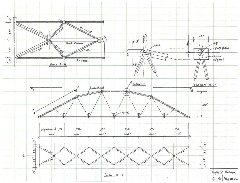
task except at the joint intersections. One possible joint detail is shown in Figure 5. In general, the eccentricity moment will have little effect on a fully triangulated offshore structure, if the amount of eccentricity is within the D/4 limit. If necessary, we can perform Finite Element Analysis (FEA) to confirm the proposed detail, if it is not covered in the codes. However, FEA should not be over-used as a standard design procedure. Since the bridge height is limited to 100 ft, the whole bend can be fabricated on the ground, then rolled up to the vertical position to mate with the bridge deck and the web members, using yard cranes. In loadout operation, failures may occur in the bridge structure, the transportation barge, the loadout skidways and the loadout bulkhead. Usually the last three items have been conservatively designed by the barge owner and the yard. The biggest uncertainty is the bridge structure. The most critical situation is when the bridge goes across the loadout bulkhead onto the barge. The usual overstress is caused by differential settlements of the barge and the bulkhead, due to imposed loads, ballast/de-ballasted water and tidal variation. In the design example, the supports have been arranged to ensure the bridge will always behave in a ‘simply-supported condition’, so that the support reactions do not vary. This will eliminate all the problems. Otherwise, the loadout process will be more complicated and costly to co-ordinate. Local structural failures have been observed in a few loadout cases before, and on-site repairs and urgent re-certification caused project delays. To reverse the loadout operation is not possible in all cases. For transportation, the barge-bridge system will experience towing forces such as heave, roll and pitch. Some restraints may be needed. But, this is a project-specific issue and cannot be covered in this article.
Installation and decommissioning
From the load-path consideration, the cheapest way to install an infield bridge is to use two derrick barges, one at each end. The bridge will be lifted in the same way as it will be positioned in the final in-place condition. Therefore, structural strengthening is not necessary during lifting. A proposed lifting arrangement is shown in Figure 6. Dual-barge lift is not a new concept. In a past project, a 1600 ton production deck, the heaviest deck in Asia at the time, was lift-installed in Indonesia, more than 35 years ago. Since the eight-leg production deck was less than 200 ft long, the two barges were tied together to perform the lift. The dual-barge system was able to inch forward in unison using anchor lines and support from a fleet of anchor handling tugs (AHTs). In the present situation, the two barges are 470 ft apart and there is not enough space to run all the anchor lines independently within a small separation. Spacer-barges may
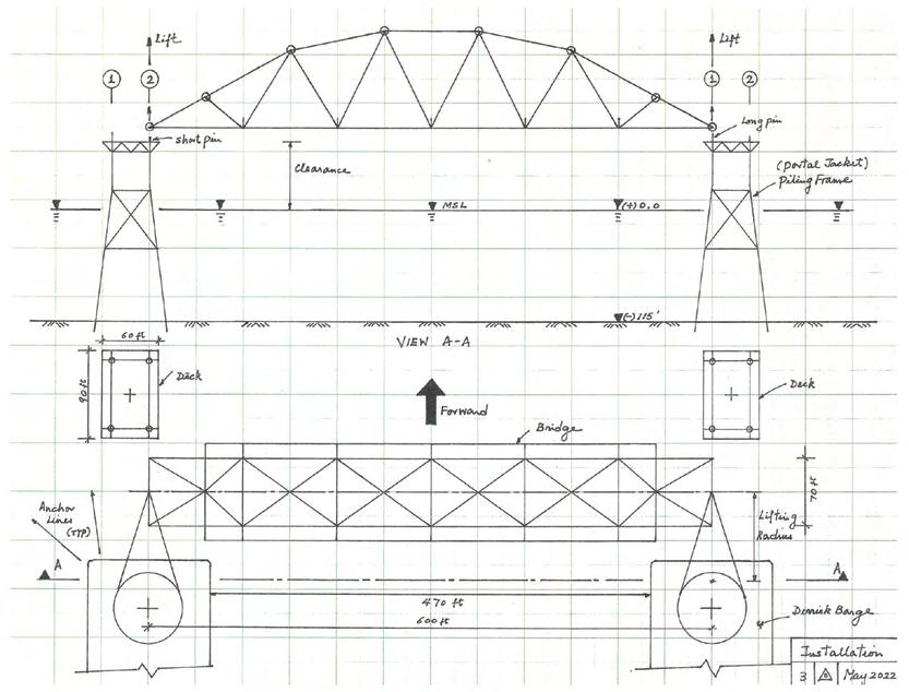
be needed to tie them together to form a single unit for lifting. Alternatively, we can lift from other points, but additional strengthening will be needed. However, the final lifting arrangement will usually be decided by the barge superintendent who is the commander for the whole operation. He is always supported by a team of engineers to double-check every step. For a two-point lift, the hook loads will not change. From experience, we believe that this is an economical solution.
CONCLUSION
In the three articles on the design economics of offshore wind farms, the feasibility of the alternative approach is presented with a few design sketches to support the argument. The offshore oil & gas industry is more than 100 years old and it has accumulated a huge amount of experiences in all areas. It also has a huge inventory of equipment. Huge savings can be realised if one can make use of this asset. Wind energy is free and abundant, and it must be possible to extract it with the least cost.
REFERENCES
[1] International Energy Agency (2021): ‘Net Zero by 2050, a Roadmap for the Global Energy Sector – Special Report’, IEA Publication, May 2021 (https:// www.iea.org). [2] Alsubal S el al (2021): ‘Life Cycle Cost Assessment of Offshore Wind Farm: Kudat Malaysia Case’, Sustainability 2021, 13, 7943, MDPI. [3] Cheung Bob L Y (2021): ‘Design Economics of Multi-Purpose Offshore Wind Farms’, The Singapore Engineer, March 2021, 22-28, Institution of Engineers, Singapore. [4] Cheung Bob L Y (2021): ‘Design Economics of Trimaran Wind Turbine Installation cum Decommissioning Vessels’, The Singapore Engineer, September 2021, 28-33. Institution of Engineers, Singapore. [5] Chen X, Li C F & Tang J (2016): ‘Structural Integrity of Wind Turbine Impacted by Tropical Cyclones: A Case Study from China’, Journal of Physics: Conference Series 753(2016) 042003. [6] ‘Tied-arch bridges’, SCI Publication UK (https://www.steelconstruction. info/index.php?title=Tied-arch_bridges&oldid=11417). [7] Tveit P (2014): ‘The Network Arch. Bits of manuscript in March 2014 after lectures in 50+ countries’. (More information may be obtained from bob.cheung@rocketmail.com)
Super-sized offshore wind installations could suffer bottlenecks from 2024
Offshore wind turbines are growing in size as technology advances and demand for renewable energy soars, but installing them could be a headache for operators as demand will outpace the supply of capable vessels by 2024, research by Rystad Energy shows. Operators will have to invest in new vessels or upgrade existing ones to install the super-sized turbines that are expected to become the norm by the end of the decade, or the pace of offshore wind installations could slow down. Wind turbines globally, excluding China, have experienced a growth spurt in recent years, rising from an average of 3 megawatts (MW) in 2010 to 6.5 MW today, with the largest in operation clocking in at 10 MW. Turbines larger than 8 MW accounted for just 3% of global installations between 2010 and 2021, but that percentage is forecast to surge to 53% by 2030. Accordingly, the demand for offshore wind turbine installation vessels worldwide, excluding China, will increase. Unable to install new and larger turbines, the first-generation installation fleet has now transitioned into maintenance and repair services for installed turbines, while operators have upgraded other vessels’ cranes in order to remain competitive in the installations market. In Europe, Asia (excluding China) and the emerging US market, turbine sizes are ramping up towards 2025 and beyond.
Vessel demands
Larger turbine installations require stronger cranes on installation vessels to lift heavier materials higher, and only a handful of purpose-built vessels available worldwide can install 10 MW+ turbines. As a result, many vessels have moved from Europe to China, where lower crane capacity vessels are still in high demand. Excluding China, demand for 12 MW+ capable installations vessels is set to increase rapidly, taking a larger share of overall demand. Out of the current fleet of purpose-built vessels, only a handful of units can install 10 MW+ turbines, and none are currently able to install 14 MW+ turbines. This will change towards 2025, as newbuilds start to be delivered and existing vessels get crane upgrades. In addition to the purpose-built vessels, some semisubmersible heavy lift vessels are being proposed for turbine installation. Generally considered too large and inefficient for installing the smaller turbines of the past, these vessels have instead landed work in the offshore wind industry, installing substations and heavy foundations. However, as the size of turbines increases, these units will fit right into the large cranes of heavy lift vessels. Vessels built early this decade are already becoming outdated as turbines grow, making owners reluctant to commit to expensive newbuilds that could be obsolete before they are profitable.
Rystad Energy
Rystad Energy is an independent energy research and business intelligence company providing data, tools, analytics and consultancy services to the global energy industry.


