


Architects
2019-2023 Portfolio
Contact Detail:
Email: DNA.architectts@gmail.com
Phone: +989374818989
Donya Rahbari

Education:
M.Sc. in Architectural Technology – Bionic Architecture, Tehran University, 2019-2023
B.Sc. in Architectural Engineering, Science & Culture University, 2014-2018
About us:
We are a group of recently graduated master’s students in architecture Technology who are gathered and worked for 4 years on different research-based and professional projects. In all these years we experienced competitions, workshops, residential projects, and even furniture designs. We believe that architecture is a way to improve lives. We try to use all the new technology and software to design creative, comfortable, and efficient spaces.
Experiences:
Bamboo-Bam, Workshop, 2021
Counstruction Workshop
-Virginia Tech & University of Art, Tehran, IranDigital Digital Fabrication, Workshop, 2020
Online Course
-Kent State University, Kent, USAKinectoscapes -DigitalFutures-, Workshop, 2021
Online Course
-Washington University, Washington, USA
Achievements:
Special Mention Winner in best project of public Building or facility by GoldenTrezzini Awards
- 2021
Honorable Mention Container City UNI.xyz Competition - 2020
First Place among participants in “Digital Digital Fabrication workshop held by Kent State University in collaboration with Tehran university of Art
- 2020
Nahal Doosti
Education:
M.Sc. in Architectural Technology – Bionic Architecture, Tehran University, 2019-2023
B.Sc. in Architectural Engineering, Shariati University, 2014-2018
Professional Experience:
Architectural Designer, Remote, 2020-2022
Drafting, 3D Modeling, Rendering & Presenting
-Iman Amini Architects, California, USA-
Architectural Designer, 2020-2021
3D Modeling, Rendering, presenting
-Admun, Tehran, Iran
Fabrication Skills:
3d print with cura software
Digital Fabrication stimulation with
Kuka robots
Laser Cutting
AmirMohammad Azizi

Education:
M.Sc. in Architectural Technology – Bionic Architecture, Shahid Beheshti University, 2018-2021

B.Sc. in Architectural Engineering, Zanjan University, 2012-2017

Competencies/skills:
• Rhino
• Grasshopper
• Python
• Autocad
• Revit
3Dmax
• Lumion
• Vray
• Enscape Photoshop
• Indesign
• Illustrator
2020 Gecon
-Designing a modular lifestyle for students5 - 8


2021
-Three observation points & a visitors’ center1 - 4
2021
Bamboo-bam
-A free form space structure9 - 12


2020
Boundry, “A robot’s dream”
-A Platform for storytelling & a short hybrid animation13 - 14

2020 Cubecell Tower

-Designing a tower in Tehran using cellular automata18 - 21
2020 Ipogami
-Compliant kinetic panel25 - 28
2019 Robotism
-Digital design and robotic fabrication workshop15 - 17
-Portable showroom22 - 24
Contents
WWF Observation Cabins
2019 Audi Showroom
Type:

Year:
WWF Observation Cabins

-Three observation points & a visitors’ center-
competition - Public Building
may 2021 - june 2021
Location:
Area:
Lagoon of Orbetello, Italy
950 m²
Status:
Special Mention Winner in best Project of Public Building or Facility By Golden Trezzini Awards

Architects:
DNA Group, Gelareh Saneyi

Brief:
In this project, we were supposed to design three different types of observation points (located on the ground, at water level, and a raised observation point), dedicated to the observation of the lagoon fauna by professionals and visitors, and a visitors’ center. The site of the project was located in the lagoon of Orbetello, an amazing environment rich in different flora and fauna. We designed the project considering different circumstances. The main concept of the project was maximum adaptation with the surrounding nature.


Contributation to the project:
Idea Development
Modeling: Rhinoceros 7.0
Rendering: Enscape 3.3 & Lumion 11

Presentation: Photoshop 2021

1
0
2 3 4
1 WWF observation cabins
Visitors' Center Water Observation Point Watchtower Watch Hut
Visitors’ Center
The visitors’ center was supposed to be positioned backward from the observation points, and it had to provide services for the oasis’ visitors. These services had to be accommodated in two buildings and they included training center, bookshop, exhibition space, guest house and restaurant ,and a reception. In the facade of the visitor center, we used recycled and reused terracotta shingles which were used in roofs of houses in Orbetello buildings for solid parts of the facade, and polycarbonate sheets for transparent parts of the facade to integrated our design with sustainability and reduce the impacts of construction on the environment.
Land


Guest house Exhibition Training center Exhibition Ticket office

Polycarbonate


Ramp stair


Roof cover Facade Structure


 7. Using waves in the facade inspired by the incremental wave from land to lagoon and the ocean
Ocean
Lagoon
inside & outside connection view with mobius strip
1. The typical roof of buildings in Orbetello area
4. 30 degrees rotation toward the lagoon
6. Final forms of visitors' center
5. Two designated locations
3. Use of gable roof in the form
2. Inspiration from gable roof houses in Orbetello
7. Using waves in the facade inspired by the incremental wave from land to lagoon and the ocean
Ocean
Lagoon
inside & outside connection view with mobius strip
1. The typical roof of buildings in Orbetello area
4. 30 degrees rotation toward the lagoon
6. Final forms of visitors' center
5. Two designated locations
3. Use of gable roof in the form
2. Inspiration from gable roof houses in Orbetello
Restaurant Void Bookshop
Terracotta shingles
2 WWF observation cabins
Watchtower
This traditional watchtower was supposed to be at maximum of 2 aboveground floors, and the structure had to enable the observation of maximum of 5 people at a time on each floor. In this watchtower, the choice of materials & architecture promotes spatial and local conscious-

ness. The goal of semi-prefabricated methods used in construction is to reduce the length of construction and use of heavy machinery on-site to eliminate tension in the environment. Used materials are chosen in a way to be sustainable and locally available with easy transportation.
Water Observation Point
Requirements for designing such a fixed or floating structure included ensuring observation of the lagoon from the level of water, which is the least traditional typology since the height of the observation window was supposed to be a maximum of 30 cm above the ground. The structure


Wooden grid
had to be waterproofed and allow the observation of maximum 5 people at a time. We used Gabion walls for the structure and used stones to show Tuscany architecture which was based on what could be sourced locally.
Straw roof cover
Wooden frame
1. The traditional form & 360 degrees view
Cork cover panels
Natural wooden columns
Short wooden beam
Wooden deck
Wooden foundation
2. Mixing forms
3. Softening edges
Opening some windows with the force of bird's weight.
4. Final plan
Cork panels

Roof wooden structural beams
Compressive ring


Gabion wall (use of old & used rebars in cage)
Sliding observation windows
Interior space of the observation point
Piling in water
1. Inspiried from the Spanish mill in the site
4. 360’ lagoon view
2. making an icon in respect of the site
5. Gabion walls local materials
3.Sky view and natural light
6.Seprate Pathes for normal & disabled people
3 WWF observation cabins
This traditional watch hut had to be located at ground level on one floor to host 10 people at a time to rest and observe. It had to include one or more sighting windows at visitors’ eye level (1.6 meters in height from the ground).


In designing the watch hut, we tried to take advantage of the interaction of children with nature because there are tremendous benefits of connecting children with nature. Fostering a connection to nature is one of the best ways to spark the love for learning at early age and cause children to learn the techniques of nature conservation and friendship


Concept development


Watch Hut
Direct Contact With Plants & Nature Going Up & Down In Space
Inspired By Animal's Camouflage Sense Of Being Among Trees Getting Lost & Discovering Nature
Accompanying Parents In Adventurous Trips
1. Considering A Cube 2. Silkworm Cocoons Form 3. Merging Silkworm Cocoon Forms 4. Subtracting Cocoons From The Cube
5. Converting The Form to 3 Levels
6. Creating Roof & Contours From Levels 7. Final form
4 WWF observation cabins
-Designing a modular lifestyle for students-
Type:
Year:
Competition - Residential

November 2020 - December 2020
Location:
Area:
Tehran, Iran
480 m²
Status:
Architects:
Honorable Mention, Container City UNI.xyz competition DNA Group, Gelareh Saneyi

Brief:
Rising rents in urban areas and shrinking the quality of living is a huge problem urban areas face because of land prices and construction costs. Modular construction is a way to address this problem. The design brief was to design a student housing concept made out of 15 shipping containers. We were supposed to devise spaces and the requirements based on how many people ideally could fit in this shipping container setup.
Aim of The Project:
This project tries to answer the student housing crisis in Iran by setting up an affordable and adaptable system for plots that have not yet been invested. we set some rules for neighboring the containers properly. Due to this goal we designed a rectangular structure based on modules that their ratio’s are based on container dimensions. However, it is adaptable to different site locations.
Contributation to the project:
Idea Development
Modeling: Rhinoceros 7.0
Rendering: Enscape 3.3 & Lumion 11
Presentation: Photoshop 2021
0
2
Gecon
5 Gecon
Generative Design


The project is flexible to adapt to various parcel sizes and morphologies. It can be inserted in a dense context or scattered context. On the top of a hill in the city, among a historical context, or a cliff. It also can be bordered by two buildings or have four open sides.


Selecting the appropriate site plan among various solutions

Determining the basic dimensions of the basic grid based on defined rules
Generating many alternatives using programming and generative design techniques


Calculating total the area of containers
Selecting better alternatives by comparing the analysis of the previous step
Calculating the amount of direct received sun
Choosing the best alternative from the options selected in the previous step based on aesthetic issues and architectural qualities
A: Dense Urban Context
B: On The Cliff
F: Among Trees
C: Historical Context
E: On The Hills
Urban Flexibility:
-Best Generated Alternatives In Terms Of Area And Direct Received SunlightSelected Alternative (Grid 11*15)
-100 Of Best Generated Alternatives In Terms Of Area-
-Best Option in Terms of Received Sunlight in 21 DECDormitory Cafe Public Space Terrace Janitor Laundry
6 Gecon
Exploded Diagram Domestic Flexibility:


In this project, two modules were defined by rules. One with 6 meters long, and the other with 12 meters long. Thus, we tried to design the interior of these two modules based on different tastes and personalities. Alternatives are different in terms of capacity, furnishing, planning, entrances, and quality of living, and users are given freedom in the organization. A multitude of configurations are possible and inhabitants can customize the space with remarkable ease.


7 Gecon
Architectural ideas & Decisions:


Insulation Importance


Insulating a shipping container is an important step of the building process if you are planning on making a container livable and comfortable They bake in hot climates and freeze in cool climates because heat moves easily through steel.


Several places were designed to let the students gather and have group activities such as studying, having fun, reading, playing, even working and earning some money as a part time job. All the details-everythingdesigned to help students have a better experience of living.
On the ground-floor, we designed a greenhouse that uses a recirculating process to grow and harvest plants and farm fish. This place provides an astonishing place where students can interact and enhance their social responsibilities.


1 2 3 Section Dormitory Cafe Public Space Laundry
Greenhouse with Acuponics system Green Wall System 3 2 Terrace Shader Design 1 Grip Fish Water Pump Fish Water Tank Filtered Reused Water Gravel Bed Plants Main Water Collector Plants Pipe to Guide water Retaining Net Water 8 Gecon
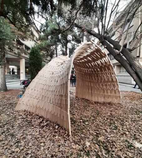
Bamboo-bam
-a free form space structure-
Type: Workshop - Pavion
Year: May 2021 - November 2021
Location: Tehran, Iran
Area: 73 m²
Status: Completed
Held By: Digital Craft House, University of Art in Association with Bamboo Research Group, School of Architecture & Design, Virginia Tech


Supervisor & Tutor: Dr. Ramtin Haghnazar, Seyyed Ali Derazgisoo, Mehran Masoudi, Danial Keramat & Jonas Hauptman
Brief:
This 3 month-long workshop was related to designing a free-form spatial structure using non-standard bio-materials with the concerns of sustainability. During the workshop, we were divided into small groups and the process included material study, sustainability, computational and structural design, form-finding, and digital fabrication. The whole workshop was done by a group of about 40 people. Our team was mainly supposed to detect appropriate bamboos in the market and test them in terms of material properties and other tests like CNC and laser cut. Furthermore, we were supposed to study different form-finding methods using various tools like Karamba, Kangaroo, Peregrine, and etc.
Contributation to the project:
Idea Development, Construction
Modeling: Rhinoceros 7.0, Grasshopper
Rendering: Rhino Render
Presentation: Photoshop 2021, Premiere Pro
0
3
9 Bamboo-Bam
Material Study
4 types of bamboo were found and preliminary studying, assessing their quality, geometrical and mechanical studying and workability was done on them. Recommendations of BS ISO for grading bamboos were followed as well. In the end, a native species of bamboo was preferred over the others.


Form Finding
The study of different form-finding methods was assigned to two groups and our group was one of them. We studied available tools and plugins for each of method and alternatives. One code for each method was prepared to let students easily use and play around with those tools. Methods studied included force density, dynamic relaxation, graphic statics, and layout optimization. Our group was in charge of studying and working with tools like “Bats”, “Kangaroo”, “Karamba”, and “Peregrine”.
System Development
In a series of brainstorming sessions, various systems were proposed until a handful of them were chosen as final candidates. The candidates were then prototyped to experience the fabrication process for each. Some prototypes had undergone little changes compared to the suggested ideas while fabricating. Finally, an evaluation process was done based on various criteria to come to conclusion what are the pros and cons of each system. This part was done by another group.
Reconfigurable geometric shape based on the extrusion of each surface of a polyhedron along the normal direction.


Material Testing:


Different types of mechanical tests and other methods have been done on bamboos so the result would help with the final output of structure’s system and form.


Alternative 1 Alternative 2
Polyhedron
Structures where members support each other along their spans.
Stacked Tapes Assembled in Rigid Structure
A circular flat joint with connector elements
Radial Selected Alternative Alternative 3 Alternative 4 Alternative 5 Alternative 6
Nexorade Star
Raw Thai Bamboo
Flamed Iranian Bamboo (Kheizaran)
Flamed Thai Bamboo
Testing CNC cut Testing laser Cut
Raw Iranian Bamboo (Kheizaran) Utilization Analysis Using Karamba Plugin
Initial Bending Tests
Testing
10 Bamboo-Bam
Measuring The Thickness
Assessing mantle thickness
Hole Cut With Drill
Evaluation & Design Workflow


Finally, suggested systems were evaluated based on visual elegance, the possibility of fabrication and assembly, structural performance, durability, and cost. Other considered factors were the usage of systems for 3 layer or 2 layer structures, needing to construct a CNC rotary system, and facilities provided in DC House Fab Lab. Considering these criteria, alternative RAdial was chosen. we developed a “digital design workflow” in a parametric modeling platform known as “grasshopper”. This digital workflow fully automates the modeling process and delivers the required outputs in a timely manner.


The workflow starts with getting two general inputs from the user: first, the wire mesh generated during the form design phase, and second, some numerical inputs about bamboo, CNC machine, Bolts and nuts, and node design preferences.


BIM Model & Prototyping


Finally, The second output is the shop drawing of the nodes and handles. These parts will be milled from plywood sheets with a 3 Axis CNC machine. Also, the shop data of bamboos is delivered. This data is used to saw and drill bamboo with a rotary CNC machine. The final output is the numerical statistics about the BIM model, such as element count and length. After all these, Prototyping starts on which some parts were constructed and tested to see if everything is working properly.
final step

After collecting and interpreting these data, it generates a completely comprehensive 3D model with labels for each element. As a result, it can be utilized as a coordination model during the assembly process.
 3. WireMesh
2. Node’s Normal (Average
3. WireMesh
2. Node’s Normal (Average
of
Neighbor Face Normals)
1. Initial Mesh
6.
Generating 3D Node (on the Plane)
5. Adjusting Node’s Plane Elevation
4. Trimming Mesh Wires (Based on Node’s Size)
7. Generating Bamboo Axes (by Adjusting Mesh Wires)
9. Blending Both Handle’s Ends
8. Generating 2D Handles’ Ends
11. Adding Node’s Tag and Pockets’ Tags (Counter Clockwise Order)
10. Generating 3D Handles and Subtracting Screw Holes
12. Adding Handles’ Tags
15. Adding Bamboo Tags (Based on
14. Adding Screw, Nuts and Washers BIM Model
13. Adding Schematic Bamboo Pipes
11 Bamboo-Bam
Custom Digital Fabrication Tools


For the bamboo poles, we understood they would need four bolts at each end and not alighned to one another to connect to their respective joints. Three-axis CNC milling machines already existed that could drill vertically through the bamboo poles. Our poles couldn’t be rolled due to the fact that the drilling was only going one way. A rotary axis that was not affordable and might not fit our CNC bed had to be purchased or we had to design a custom one. We decided to go for the latter solution.


Fabrication Process And Assembly


The fabrication started with placing the three base elements in a proper position on the ground of University of Art in Tehran. Bamboos that had thicker mantle and were larger in diameter were placed on the basement structure using screw. Middle structures of basements which were similar to six-winged stars


were then added and fixed to the bamboos of basements at the top. The three basements of the structure started to be constructed at the same time until they met each other in the middle. Bamboos and nodes which were located in the perimeter of the structure were assembled in the end in order to prevent the overthrow of the structure.

1 1 4 2 5 3 6 7 8 10 9 2 3 12
Bamboo-Bam
4
Boundry, “A robot’s dream”
-A Platform for storytelling & a short hybrid animation-


Type: Workshop - Pavion

Year: November 2020 - December 2020
Location: Tehran, Iran
Awards: First Place in “Digital Digital Fabrication” Workshop / United States / Kent State University
Status: Completed
Held By: Tehran University of Art in Collaboration With Kent State University & DC House
Supervisor & Tutor: Dr. Ebrahim Poustinchi
Brief:
This workshop focused on a robotically augmented design using Maya. The workshop was seeking an in-between-between the digital fabrication, simulation, and digital modeling as a possible design and a thinking medium to combine the restrictions and opportunities of each of the mentioned mediums into a hybrid design process. It also visited the idea of a digital fabric and context as a platform for storytelling and atmosphere creation.
Contributation to the project:
Idea Development
Modeling: Maya 2020
Rendering: Arnold
Presentation: Premiere pro 2020
0
13 Boundry-”a robot’s dream”
1.Material Phsase
At first, robots pour the raw balloon material through the cone and slide to get the first process.


Our Story:
2.Balloon Factory

With the help of robots the the “Balloon Factory” starts the process of producing balloons.


3.Balloon Production
Huge amount of balloons pop up through the cone shaped chimney.
The digital medium used in this project creates an unreal environment with a narration. In this platform. The story is about a dark and gloomy crowded city after a traumatic crisis where there is no hope, and robots are bringing hope and excitement to the city. In fact, robots are running a factory in which balloons that are the symbol of hope are made. Each robot is responsible for a specific task. One is pouring the initial material, the other one is picking the initial material and using it as fuel for an engine. Other robots are obliged to move gears in order to inflate balloons in glass jars. Finally, inflated and colorful balloons are produced and are blown out of the trumpet. One robot is responsible for giving produced balloons to children who play the main role in making the world a better place to live..In the end, some of the balloons which are the symbol of hope are freed to fly upward. Two robots are standing on an arch which is the symbol of the past. These two robots collaborate and help in overthrowing the arch so that those balloons can spread hope easily throughout the whole city and this action is an indication of liberation from the past and boundaries made by human beings. In fact, in this story, robots are critical

in pushing back the boundaries and this is like a dream for robots. That is why this project is called a robot's dream. In other words, robots which are always considered as enemies for humans, offer their helping hands to humans, and this is a dream that a robot can have
4.Flying Balloons

Some of the producted balloons get to the hands of children by a robot to make them happy and others fly to share the happiness borderless.
5.Boundry
Borders, bariers & obstacles -phisycal or intellectual- such as beliefs, rules, tradition & ... could stop the thriving process but it only needs hard work!
6.Freedom
Finally the balloons will fly high and get anywhere to share happiness and joy. All with the help of “ROBOTS”.
14
Boundry-”a robot’s dream”
ROBOTISM
- Digital Design and Robotic fabrication Workshop -
Type: Workshop - Pavilion
Year: Autumn 2019
Location: University of Tehran - Tehran
Area: 40 m²
Status: Constructed
Supervisor: Dr Mohammad Reza Matini
Held By: Tehran University in Collaboration With Art University & DC House
Brief:
ROBOTISM was a ten-day workshop held in December 2019 at the University of Tehran, focused specifically on the computational design and robotic fabrication. The workshop included 45 undergraduate and graduate architecture students who were divided into groups of 5 to 6 and practiced working with robot. KUKA KR6 with a KRC2 controller was used in this workshop.
Contributation to the project:
Idea Development
Modeling: Rhinoceros 6.0 & Grasshopper

Rendering: Rhino Render
Presentation: Photoshop 2020 & Indesign

0 5
15 Robotism
Initial experiments with robots


In the first exercise of workshop, students were asked to draw continuous curves with specific patterns in grasshopper 3d and define the motion path of the robot and after generating the G-Codes they started to light painting by using a simple LED as a tool that was placed on the robot’s head. In the next exercise, each group was asked to design a structure making use of wooden pieces with specific sizes and numbers, and assemble it with Pick and Place technique, making sure that it could maintain its stability throughout the assembly without the need for screwing or gluing.


Form Finding
After performing introductory tasks by the teams and getting acquaintance with practical challenges viz properly defining planes to prevent collision of the robot arm with its surroundings, and installation of pneumatic gripper and air pump, students embarked on designing a pavilion on a scale of one to one. The major restriction to be considered in designs was the amount of available material, 40 square meter of 18-mm plywood. All of the proposals were assessed by the jury, and eventually one of them was opted for the final project. Modification were also made to finalize the design.

 1. Surface 2. Contouring Surface
16
3. Dividing Contour Lines 4 .Locating Plywoods
Robotism
DIVIDING THE PAVILION TO 9 ARCHES EXPLORING DIAGRAMS OF DIVISION


Initial experiments with robots

The final design had to be prepared for the assembly process. Given the limitation of robot reach to 1.6m and the conditions of the site, we decided to halve the arch, and also split each half to 4 and 5 sections respectively, making a total of 9 sections. Two methods were proposed for connection of wooden pieces; utilizing a glued roller to which each wooden piece would be rubbed by the robot and placed at the its position, or using a collaborative human-robotic fabrication technique in which someone would use a


pneumatic nail gun to fasten objects together after being placed by robot. Considering some practical issues and time constraint, the latter was preferred. The fabricated sections in the workshop space were transported to the campus and assembled over two hours.


 ROBOTIC FABRICATION ANALYSIS
Place the wooden pieces
Pick the wooden pieces
ROBOTIC FABRICATION ANALYSIS
Place the wooden pieces
Pick the wooden pieces
17 Robotism
Assemble The wooden pieces
5 Cubecell tower
- Designing a tower in tehran using cellular automata -

Type: multifunctional tower
Year: 2020
Location: Tehran
Area: 90000 m²
Status: Concept & Reasearch

Architects: DNA Group, Zahra Salehi

Brief:
The problem of the project was the design of a multifunctional 60-storey tower. According to the studies, in addition to commercial and administrative services, we provided cultural and recreational use. Due to the needs and factors such as structure, energy, and performance needs, we came to the conclusion that the use of a computational process will be beneficial in achieving a faster and more efficient response. We turned to agent-based algorithms, specifically cellular automata. In this path, the intended goals such as the ability to prefabricate, change and reproduce and add parts at different times of this cellular system have been selected. Finally, by choosing several alternatives and analyzing them by using the Karamba plugin to check the structure, the energy analysis plugins in Grasshopper, and CFD to check the final form and shell against wind currents, the best option was chosen.
Contributation to the project:
Idea Development
Modeling: Rhinoceros 6.0 & Grasshopper & Python
Rendering: Lumion 10
Presentation: Photoshop 2020
0 1
18 Cubecell Tower
cellular automaton


A cellular automaton consists of a regular grid of cells, each in one of a finite number of states, such as on and off (in contrast to a coupled map lattice). The grid can be in any finite number of dimensions. For each cell, a set of cells called its neighborhood is defined relative to the specified cell. An initial state (time t = 0) is selected by assigning a state for each cell. A new generation is created (advancing t by 1), according to some fixed rule (generally, a mathematical function)that determines the new state of each cell in terms of the current state of the cell and the states of the cells in its neighborhood. Typically, the rule for updating the state of cells is the same for each cell and does not change over time, and is applied to the whole grid simultaneously, though exceptions are known, such as the stochastic cellular automaton and asynchronous cellular automaton.

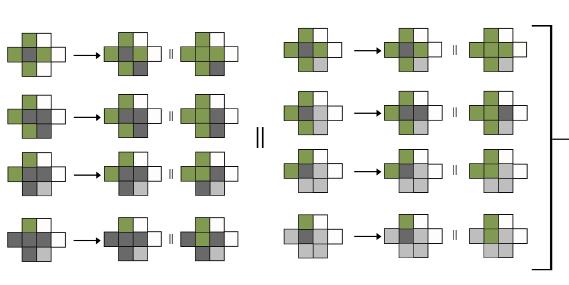
Void units: These units only form the edge of the work, and no box is ultimately drawn for them.
White units: In this part of the code, these units are randomly converted into Cells, Terraces, and Spaces.
Fixed units around the core units: These units are considered fixed and do not change in any generation or in any initial state.


Core units: These arrays are also considered fixed and are essentially the structural part and the main. communication core of the building.


Neighborhoods of each cell selected based on Neumann’s :
First method : The number of generations is arbitrary and the number of classes is defined separately.


1-If a Cell has a neighboring Space or Terrace and if one of its neighbors is Void, it will be randomly converted to a Terrace or Space.

2-If a Terrace has one or more Terrace neighbors, it can be randomly converted to a Cell or Terrace.
Second method : The number of levels required determines the number of generations.
3-If a Terrace has one or more Terrace neighbors, it can be randomly converted to a Cell or Terrace.
4-If a Terrace has one or more Terrace neighbors, it can be randomly converted to a Cell or Terrace.
5-If it is a unit of Space and has four Cell neighbors, it becomes a Cell.

Cell Unit Terrace Unit Space Unit 19 Cubecell Tower
Structure
The basis of designing the plans in this project is square modules. The system which has been chosen would be beam and column structure (bending frame) in which the beams of the stories used in dimension the square plan modules pattern and the length of spans are equal to the length of the main module. One of the reasons for choosing this structure would be the reproducibility of the structure based on designing the 0 to 15th floor to add some modules to the structure. Also, this structure allows repeating the pattern of filling and removing the

modules in the plan environment in the height of the structure. Other areas of choosing the steel structure compared to concrete structures would be the reduction of the cross-sectional dimensions of structural elements and also the higher construction speed which in turn would reduce costs during project implementation. In addition to the steel frame, this structure would have also benefited a truss core in bearing the gravity and lateral loads which would be transferred to the foundation by the central core.

The first alternative for structural analysis by the KARMBA plugin was a metal frame with a core. In the next alternative, 2 one-story belt trusses and truss arms at the retreat site in the façade and the last were added. In the last, the height of these members increased to two floors. By browsing the data of structure analysis finally the second structural alternative was chosen as the optimal alternative.


In interior design, according to the functional needs in the early stages of the project, as well as in explaining the code, we have had a smoother path. One of the main goals was to make maximum use of sunlight, as well as to create various spaces and green terraces to control sunlight and create a favorable atmosphere for people.


CFD Analysis Final form Load path Karamba analysis Structure
Alt 1 Alt 2 Alt 3 Alt 4
20 Cubecell Tower
Vertical circulation design


7 passenger elevators and two freight elevators are located in the central core of the building. Of these 7 elevators, 3 elevators belong to the classes with a multiple of 10, two elevators are even multiples and the other 2 elevators are odd multiples. There are also floors with a multiple of 10 safe floors and staff dining halls. The unloading space of core elevators is equivalent to the per capita declared by international standards. There are also two escape routes Located in the core. In addition to the vertical communication routes and escape routes in the commercial and cultural floors, 4 elevators
Plans
and two other escape stairs have been installed which are located on both sides of the building and the closest place to the exit doors.
In addition to the core of the building and through the parking lot, the office workers can access the separate entrance from the southeastern facade of the building by several elevators that go to the office lobby.


However, on the same front, there are several other freight elevators that continued to the cultural classes, and the access of docking machines to this front has been established.

Commercial: 1) Core 2) Commercial Space 3) WC 4) Freight Elevator lobby Cinplex: 1) Core 2) Plateau 3) WC 4) Freight Elevator lobby 5) Control room 6) Cinema Hall 7) Office Food Court: 1) Core 2) WC 3) Store room Sky lobby: 1) Core 2) Lobby Office: 1) Core 2) Office units corridore 3) Meeting room 4) Relaxation room Office: 1) Core 2) Office units corridore 3) Meeting room 4) Open space office 5) Relaxation room Freight Elevator Tower staff Elevator General Elevator Official Elevator (safe floor) Escape Elevator Official Elevator Commercial Elevator Restaurant Safe floor/ Dining hall Safe floor/ Dining hall Sky lobby Safe floor/ Dining hall Safe floor/ Dining hall Official lobby Museum Cineplex Restaurant Ground Commercial Hyper market Parking Vertical circulation Land use types
21 Cubecell Tower
Audi showroom
- portable showroom -
Type: Showroom
Year: 2019
Location: Tehran
Area: 1020 m²
Status: Concept & Reasearch
Architects: DNA Groups
Brief:
The purpose of this project was to design a mobile car exhibition, which according to the choice of Audi company, the final form of the exhibition was chosen and designed inspired by the logo of this factory. Since this exhibition should be able to be moved, at the end of the research, the construction method was chosen using the active bending method. Bending-active structures are structural systems that include curved beam or shell elements that base their geometry on the elastic deformation from an initially straight or planar configuration. In this project, all the facilities, including sanitary facilities, ventilation systems, and light and water supply, were selected using mobile facilities and according to the final goal of the project. In fact, all these facilities can be off-grid.
Contributation to the project:
Idea Development
Modeling: Rhinoceros 6.0 & Grasshopper & Sketchup

Rendering: Lumion 8

Presentation: Photoshop 2020
0 7
22 Audi Showroom
Structural design
In a dynamic context of rapidly evolving user needs, transformable structures anticipate and respond to changing demands in minimal time, with minimal effort. Innovative structural concepts should supplement the design of transformable structures to increase their structural and functional efficiency. Therefore, we defined transformable active bending as a combination of the principles of mobility and


rapid assembly of transformable structures, and the utilisation of bending deformations in bending-active structures. Although it is the availability of state-of-the-art design modelling techniques and structural modelling tools that facilitate design exploration and form-finding of bending-active structures, accurate modelling of the complex relation between their geometry and bending behaviour remains challenging


Design consept the design concept started with the Audi logo and four rings. this formation has a linear orientation that is appropriate for exhibition circirculation. then these rings repeated and scaled and in the following, they moved in z axis to make the considered shapes.

Semi-transparent panels
Main structure
Complementary structure

Floor panels
Substructure
Foundation
 Structure diagram
Bending active creation
Load path
Structure diagram
Bending active creation
Load path
23 Audi Showroom
Vertical forces Lateral forces
Watercurtain system


A water curtain is defined as a line of closely spaced sprinklers (or a single sprinkler) in combination with draft stops that are intended to retard the passage of fire through an opening


Holographic system
A holographic display is a type of display that utilizes light diffraction to create a virtual three-dimensional image of an object. Holographic displays are distinguished from other forms of 3D imaging in that they do not require the aid of any special glasses or external equipment for a viewer to see the image.


CHP
Cogeneration or combined heat and power (CHP) is the use of a heat engine or power station to generate electricity and useful heat at the same time. Trigeneration or combined cooling, heat, and power (CCHP) refers to the simultaneous generation of electricity and useful heating and cooling from the combustion of a fuel or a solar heat collector. The terms cogeneration and trigeneration can be also applied to the power systems generating simultaneously electricity, heat, and industrial chemicals – e.g., syngas or pure hydrogen (article: combined cycles, chapter: natural gas integrated power & syngas (hydrogen) generation cycle)...

2 1 3 3 1 2 3
Maquette & Details (SC: 1/5)
24 Audi Showroom
ipogami
- compliant kinetic panel -
Type: Facade Panel
Year: Autumn 2020
Location: University of Tehran - Tehran
Status: Constructed

Supervisor: Dr Mohammad Reza Matini
Brief:
In this project, the goal was to design a kinetic panel that responses due to intense sunlight or rain, to provide comfort conditio. In this regard, inspired by the structure of the Ipomea flower -how it blooms- and using the origami method, the final panel was designed. This origami, which is known as NASA origami, used in various NASA projects. Prototyping this structure in different ways using different materials and construction methods, considering proper response and efficiency, in the end, a combination method was chosen. The final structure was made using a flexible part and a rigid part. The rigid part is used to provide strength and the flexible part is used to provide opening and closing ability. Using cable and spring steel is also to integrate the main part to the stepper motor. This compliant kinetic panel is equipped with a water and light sensor and provides the final goal by using an Arduino Uno and a stepper motor.

Contributation to the project:


Idea Development
Construction
Modeling: Rhinoceros 6.0 & Grasshopper
Presentation: Adobe premier

0 8
25 Ipogami
The purpose of designing panel:

Tested fabrication methods:
1: PP (PolyPoropylene)
2: PVC (polyvinylChloride)
The movement in many biological kinetic structures is often based on compliant mechanisms that are integrated into larger flexible organs. Compliant mechanisms where technical devices obtain their motion by the flexibility of their members and functionalize large elastic deformations. In this flower configuration, all five petals are fused together to one continuous corolla surface. While other flowers can change their shape by sliding or overlapping their petals individually, Ipomea has to adjust its shape by means of folding and bending its entire corolla surface. It combines a soft and thin lamina on the one hand and five leathery mid-petaline bands on the other. A spiral movement of the bands begins with a sudden burst of the bud shell. Once the thin lamina that connects the bands is torn apart, the five bands start to separate from each other and bend outwards in a slower helical movement.


Since origami relies on the deflection of flexible materials it is a compliant mechanism. The origami mechanisms examined herein are flat-folding in their final-folded state, and so they are part of a subgroup of compliant mechanisms called lamina emergent mechanisms. The chosen origami for this research is Starshade, Flasher( Jeremy shafer)


Tested fabrication methods:


1 : Integrated
3: High impact Polystyrene

4: PES-PVDF
3 : Stiff & flexible
1: Fabric + 3D print
2:
3:
In the process of panel design and construction, some of the possible methods and materials given in the previous section have been used and each has been tested. But due to various reasons such as lack of flexibility, being heavy, difficult to make, high cost, etc., they were finally removed. The final design is actually a combination of these methods, especially the use of fabric and plexiglass to provide flexibility and strength at the same time.
Mechanism Inspiration
NASA Origami
Fabric + Glue Chosen Method
Fabric + CNC sewing
2 : Spring hinge Metal sheet + Spring hinge
PVC
Metal sheet + Spring hinge 3D printing on Canvas
PVC
Bands Corrola
Valley Fold
Valley Fold
Mountain Fold
26 Ipogami
Mountain Fold
7 strands


Tensile strength


Digital techniques


Abrasion Resistance


What is Arduino Uno?


Arduino Uno is a microcontroller board based on the ATmega328P (datasheet). It has 14 digital input/output pins (of which 6 can be used as PWM outputs), 6 analog inputs, a 16 MHz ceramic resonator (CSTCE16M0V53-R0), a USB connection, a power jack, an ICSP header, a reset button. It contains everything needed to support the microcontroller; simply connect it to a computer with a USB cable or power it with an AC-to-DC adapter or battery to get started.
“Uno” means one in Italian and was chosen to mark the release of Arduino Software (IDE) 1.0. The Uno board and version 1.0 of Arduino Software (IDE) were the reference versions of Arduino, which now evolved to newer releases. The Uno board is the first in a series of USB Arduino boards, and the reference model for the Arduino platform; for an extensive list of current, past, or outdated boards see the Arduino index of boards.
 Stainless Steel Wire (Plastic coated)
1: CABLE (FISHING LINE)
2: SPRING STEEL
4: TARPAULIN
Stainless Steel Wire (Plastic coated)
1: CABLE (FISHING LINE)
2: SPRING STEEL
4: TARPAULIN
yeild
Resilance
resistance (In Low Thicknesses) Light
resistance
cut
cost Strong Flexible
protection
resistance
3: PLEXIGLASS (PMMA)
High
strength
Pliability Deformation
Heat
Clean
Low
Heat
Water
1: 3D print (FDM method)
2: Milling machine (Metal)
1 2 3 4
3: Laser cut
Chosen method : Fabric + Glue
Rain sensor
Arduino Uno Photcell
Thermo electric cooler
Stepper motor
27 Ipogami
The spring are not allowed to have motion in their place in fabric.


 Membrane + Plexiglass
Spring steel Cable Stepper motor & CNC Steel
Glass
Cable and spring steel must have specified distance to avoid friction.
spring steel Cable
The core of panel which keeps the spring steels in center.
Exploded diagram
The performance of the panel
Flexible part
Membrane + Plexiglass
Spring steel Cable Stepper motor & CNC Steel
Glass
Cable and spring steel must have specified distance to avoid friction.
spring steel Cable
The core of panel which keeps the spring steels in center.
Exploded diagram
The performance of the panel
Flexible part
28 Ipogami
Rigid part
2023
Architects
