3.2Risks of cavitation:...............................................................................................................................30
3.3Benefits of using low NPSH impeller:..................................................................................................30
3.4Consequences by using a low NPSH impeller:....................................................................................30
3.5Calculation of NPSHa..........................................................................................................................30
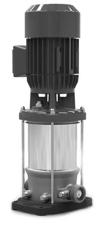
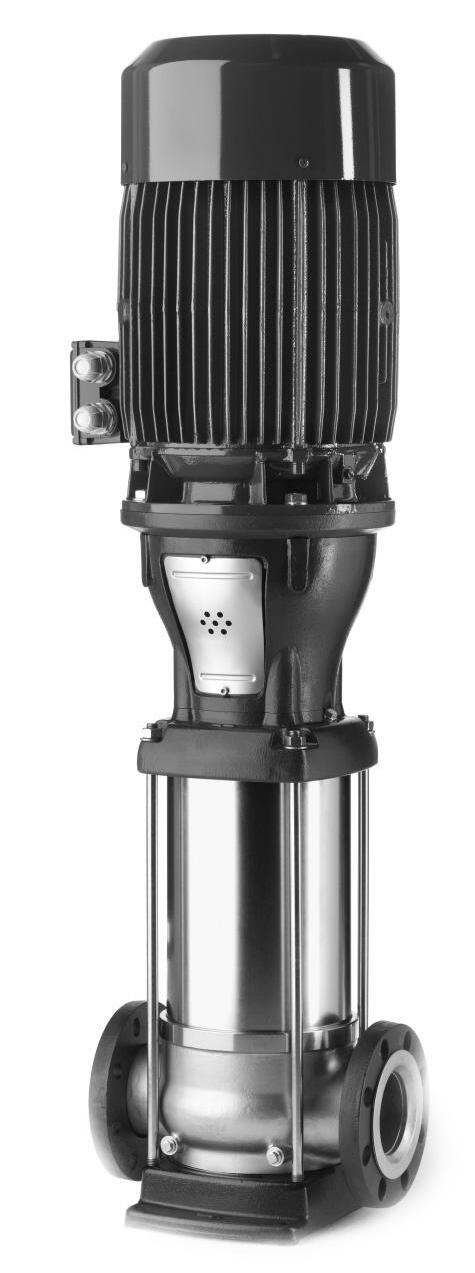
The vertical, single or multi-stage centrifugal pump series are designed for pumping clean, or lightly aggressive, watery mediums.
Suction and discharge of the pump are in-line, making the pump easy to install.
The hydraulic assembly is driven by an electric motor. All hydraulic parts of the pump are made of stainless steel.
The vertical multi-stage centrifugal DPV pumps are produced by Duijvelaar pompen.
1.2Model key
Table 1: Model key Example DPVSF 85/3-1 B
DP VS F 85 /3 -1 B
LabelDP
Material/ Construction
VC
Product Label
Cast Iron pump foot and top bracket hydr. 1.4301 / AISI 304
V All wetted parts Stainless Steel 1.4301 / AISI 304
VM All wetted parts Stainless Steel 1.4301 / AISI 304 with closed coupled motor
VS All wetted parts Stainless Steel 1.4401 / AISI 316
Connections E
Male thread (with non-return valve insert)
Oval flange with female thread
F Round flange
V Victaulic connections
T Tri-clamp connections
85 Capacity in m3/h at Q.opt
/3
Number of stages
/3-1Number of stages of which one stage with reduced head
LLow NPSH impeller (model 2,4,6,10,15,25 en 40)
VTwo stages of which one stage with reduced head and one impeller low NPSH
WThree stages of which two stages with reduced head and one impeller low NPSH
B/CDesign version
1.3Operation
During centrifugal operation of the pump a negative pressure is created at the inlet of the impeller. This negative pressure enables the medium to enter the pump at the suction connection (A).
Every stage (B) consists of an impeller and diffuser. The passage of this stage determines the capacity of the pump. The diameter of the stages is related to the centrifugal forces and its “stage pressure”: the more stages, the more pressure.
This total capacity and raised pressure will be guided to the outside of the pump, between the pump stages and the outer sleeve (C) and the medium will leave the pump at the discharge connection (D).
Figure 1: DPVF 85
1.4Measuring, draining and venting
The pump is provided with plugs for measuring, draining and venting.
Connection (E) is meant to drain the inlet part of the pump. Or to measure the inlet / suction pressure using a G ¼ connection.
Connection (F) is meant to drain the outlet part of the pump. Or to measure the discharge pressure using a G ¼ connection.
Connections (G) are meant to vent the pump system when the pump is not in operation. Or to measure the discharge pressure of the pump using a G 3/8 connection.
1.5Working range
The working range is depending on the application and a combination of pressure and temperature. For specific and detailed limits please consult the working ranges as described in the chapter 1.8 Modular selection. The overall working range of the pumps can be summarised as follows:
Table 2: Specification of the working range
Minimum inlet pressureNPSHreq. + 1m
Viscosity [cSt] 1-100 2
Minimum frequency [Hz] 30
Maximum frequency [Hz] 60 4
Allowable size of solids pumped 5µm to 1mm
1.If the ambient temperature exceeds the above value or the motor is located more than 1000 m above sea level, the motor cooling is less effective and could require an adapted motor power. See table 5: Motor load dep. sea level or amb. temp or please contact your supplier for more detailed advice.
2.Deviation in viscosity and/or density could require an adapted motor power. Please contact your supplier for more detailed advice.
3.The free space above the motor cooling fan must be at least 1/4 of the diameter of the inlet of the cooling fan in order to have a sufficient flow of (cooling) air.
4.Pumps that are intended for 50Hz operation, may not be connected to 60Hz power supply.
1.5.1Minimum capacity
For minimum capacity at medium temperature of 20 oC, see table: Minimum capacity (Qmin); for higher temperatures, see table 3.
To prevent the pump from overheating, gathering gas, cavitation etc. a minimum capacity has to be secured. The minimum capacity corresponds to all percentage of the optimum flow Qopt in relation to the temperature of the liquid pumped.
Table 4: Minimum capacity vs.temperature (in % of Q optimum)
Table
1.5.2Ambient temperature and higher altitude
If the ambient temperature exceeds the above value, or if the motor is located more than 1000 m above sea level, the motor cooling is less effective and could require an adapted motor power. See below table for the increased percentage of the motor power or contact your supplier for more detailed advice. Table 5: Increase of required motor power
1.7Pump bearing
Medium lubricated stage bearing Tungsten Carbide against Ceramic
Optional pump bearing Tuc/TuC:
In case of severe applications or using conditions, such as hot water, boiler feed (max 140 oC or when the pump experiences un avoidable dry running for a short time. The standard ceramic bearing material can be replaced / exchanged by a more resistant TuC/TuC bearing material.
Due to the specific material characteristics of Tungsten Carbide, the TuC/TuC material is even more resistant for the above mentioned severe conditions and will enhance the durability and lifecycle of the pump.
1.6Basic material variants
Table 6: Basic material variants
Model Hydraulic Casing Sealing V 1.43011.4308EPDM
VC 2-60 & 1251.4301JS1030EPDM
VC 851.4301JL1040EPDM
When combining the use of the optional TuC/TuC bearing material and the optional low NPSH kit, the pump can be made even more suitable for the above mentioned severe applications or using conditions.
The optional combinations TuC/TuC bearing material and low NPSH kit are available for the vertical pump models DPVCF 2,4,6,10,15, 25 and 40.
Up to now only the optional TuC/TuC bearing material is available for pump models DPVCF 2 up to and including 125.
For other possible pump options or features, please contact our sales department.
1.8Modular selection
To suit almost every application the pump is assembled out of modules which can be selected depending on the required working range. Basic modules are:
• Basic pump model, which defines the capacity, pressure and basic material.
Temperature range -20 up to 140 oC, with the exception of the DPV 125 this pump can be used upto 120 oC.
• Connections, which define the suction and discharge connection as well as the base plate. VE casing (with non return valve) max. temperature 90 oC. Other connections have same temperature range as basic pump model.
• Sealings, which define the elastomers, the mechanical seal and the shaft seal type.
Temperature range, see chapter 5.1
• Electric motor, which defines all requirements of the motor such as motor size, power, voltage, frequency and all possible motor accessories. Due to mono-block motor version VM, max. fluid temperature is 60 oC
1.9Approvals
CE Conformity with European Safety Directive
ACS Drinking Water Approval (F)
WRAS Drinking Water Approval (GB)
ATEX Conformity with “ATmosphères EXplosibles” Directive
2Performance characteristics
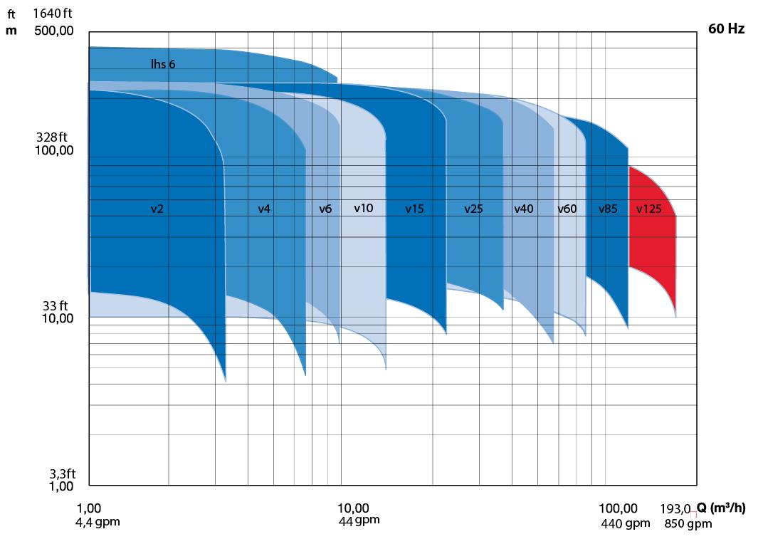
2.1Performance range
2.2Performance curve details
The performance diagrams give a global overview of all the pump models the shaded models are mentioned in this documentation. Detailed characteristics are given for each model showing the hydraulic efficiency, NPSHreq, and shaft power as well.
The performance of the pump depends on the number of stages. As per example:
DPV 4/2 B:model DPV 4 B2 stages with 2 full head impellers
DPV 85/4-1 Bmodel DPV 85 B4 stages with 3 full head impellers and 1 reduced impeller
The detailed performance curves are in accordance with ISO 9906: 2012 (Grade 3B).
The motors used for the measurements are calibrated motors with a specific rotational speed. Therefore the performance data, like Q/H, efficiency and shaft power used for published curves are converted to the average speed per motor power. To refine this data the published data has to be corrected accordingly.
The published curves and data mentioned on the pump are based on the following rotational speed:
The characteristics given are based on:
• De-aerated water at a temperature of 20 °C
• Density of 1,0 kg/dm3
• Kinematical viscosity of 1 mm2/s (1 cSt)
Figure 2: Performance range DPV(C/S) B/C 60Hz
2.3Minimum efficiency index
The minimum energy-efficiency level according to ErP regulations for water pumps is specified by the minimum efficiency index MEI. A high value indicates a high efficiency of the determined pump. From 1 January 2015 on the minimum efficiency index (MEI) for standardised water pumps is ≥0.4.
The following MEI values apply for the pump range design version B/C:
Table 7: Minimum efficiency index
Pump range
DPV 2BMEI ≥ 0.70
DPV 4BMEI ≥ 0.70
DPV 6BMEI ≥ 0.70
DPV 10BMEI ≥ 0.70
DPV 15CMEI ≥ 0.70
DPV 25BMEI ≥ 0.70
DPV 40BMEI ≥ 0.70
DPV 60BMEI ≥ 0.70
DPV 85BMEI ≥ 0.60
DPV 125BMEI ≥ 0.70
2.4Performance with variable frequency drive
The minimum frequency of the DP motor should be limited to 30Hz. When the rotational speed exceeds the nominal speed of the motor, make sure that the power output of the motor is suitable to drive the corresponding pump model.
The performance of the pump differs from the fixed speed performance according to the recalculation scheme.
2.5How to read the values from the curves
To find the required hydraulic information from the published curves, it is important to know the application in which the pump has to be installed. There are two main distinction to be made:
AFlow determined (like booster sets and cleaning) Opening taps
The required motor power can be read in the curve’Power input’.
Attention: the power value as mentioned in this curve is the required power per stage. For some pump types there are two lines in the curve this is related to the full impeller or reduced impeller [-1].
Figure 3: Performance characteristics
Figure 4: How to read the values from the curves
O Calculated duty point
Actual hydraulic performance
A Flow determined
B Pressure determined
3227/04072008
Pump size / no of stages.
Installed motor power
Capacity @ Pressure
NPSH (m)
Hydraulic efficiency (%)
Required power (P2)
2.6Hydraulic performance curve
Förderhöhe TDH
Hauteur
Prevalenza
Opvoerhoogte Altura
2/22 3,0 kW
2/20 3,0 kW
2/18 2,2 kW
2/16 2,2 kW
2/14 2,2 kW
2/12 1,5 kW
2/11 1,5 kW
2/10 1,5 kW
2/9 1,1 kW
2/8 1,1 kW
2/7 1,1 kW
2/6 0,75 kW
2/5 0,75 kW
2/4 0,55 kW
2/3 0,37 kW
2/2 0,37 kW
Eta
Leistungsbedarf
Opgenomen
Fördermenge/Flow/Débit/Portata/Capaciteit/Caudal
Figure 5: Performance curve DPV(C/S) 2 B - 60Hz - 2 pole
2.7Hydraulic performance curve DPV(C/S) 4 B - 60Hz - 2 pole (3500 rpm)
Förderhöhe TDH Hauteur Prevalenza
Opvoerhoogte Altura
4/18 5,5 kW
4/16 5,5 kW
4/14 4,0 kW
4/12 4,0 kW
4/11 3,0 kW
4/10 3,0 kW
4/9 3,0 kW
4/8 2,2 kW
4/7 2,2 kW
4/6 1,5 kW
4/5 1,5 kW
4/4 1,1 kW
4/3 0,75 kW
4/2 0,55 kW
Leistungsbedarf Power Input Puiss. abs. Potenza ass. Opgenomen vermogen
= 1000.0 kg/m³
Fördermenge/Flow/Débit/Portata/Capaciteit/Caudal
Figure 6: Performance curve DPV(C/S) 4 B - 60Hz - 2 pole
2.8Hydraulic performance curve DPV(C/S) 6 B - 60Hz - 2 pole (3500 rpm)
Förderhöhe TDH
Hauteur Prevalenza Opvoerhoogte Altura
01020304050 [US.gpm]
010203040 [IM.gpm]
6/18 7,5 kW
6/16 7,5 kW
6/14 5,5 kW
6/12 5,5 kW
6/11 4,0 kW
6/10 4,0 kW
6/9 4,0 kW
6/8 3,0 kW
6/7 3,0 kW
6/6 2,2 kW
6/5 2,2 kW
6/4 1,5 kW
6/3 1,1 kW
6/2 0,75 kW
6/1 0,37 kW
Leistungsbedarf Power Input Puiss. abs. Potenza ass. Opgenomen vermogen
=
Fördermenge/Flow/Débit/Portata/Capaciteit/Caudal
Figure 7: Performance curve DPV(C/S) 6 B - 60Hz - 2 pole
2.9Hydraulic performance curve DPV(C/S) 10 B - 60Hz - 2 pole (3500 rpm)
Förderhöhe TDH
Hauteur
Prevalenza
0204060 [US.gpm] 02040 [IM.gpm]
10/11 7,5 kW 10/10 7,5 kW
10/9 7,5 kW
10/8 5,5 kW
10/7 5,5 kW
10/6 4 kW
10/5 4 kW
10/4 3 kW
10/3 2,2 kW
10/2 1,5 kW
10/1 0,75 kW
Opvoerhoogte Altura 0246810121416 [m³/h]
[l/s] NPSHR 5 1 [m]
Leistungsbedarf Power Input Puiss. abs. Potenza ass. Opgenomen vermogen
= 1000.0 kg/m³ 20101081-B/0
Fördermenge/Flow/Débit/Portata/Capaciteit/Caudal
Figure 8: Performance curve DPV(C/S) 10 B - 60Hz - 2 Pole
2.10Hydraulic performance curve DPV(C/S) 10 B - 60Hz - 4 pole (1750 rpm)
Förderhöhe TDH
Hauteur
Prevalenza
Opvoerhoogte Altura
10/7 0,55 kW
10/6 0,55 kW
10/5 0,55 kW
10/4 0,55 kW
10/3 0,55 kW
10/2 0,55 kW
10/1 0,55 kW
Leistungsbedarf Power Input Puiss. abs Potenza ass Opgenomen vermogen
Figure 19: Performance curve DPV(C/S) 85 B - 60Hz - 4 pole
2.21Hydraulic performance curve DPV(C/S) 125 B - 60Hz - 2 pole (3500 rpm)
Förderhöhe TDH
Hauteur
Prevalenza
Opvoerhoogte Altura 020406080100120140160180200
Leistungsbedarf Power Input Puiss. abs. Potenza ass. Opgenomen vermogen
=
Fördermenge/Flow/Débit/Portata/Capaciteit/Caudal
Figure 20: Performance curve DPV(C/S) 125 B - 60Hz - 2 pole
3Low NPSH impeller
3.1General
Low NPSH impeller
For the pump type series DPV(S/C)(F) 2, 4, 6, 10, 15, 25 and 40 it is now possible to have a low NPSH solution as option. This solution based on a new designed low NPSH impeller and modified stage casing the NPSH curve of the pump will have much better values throughout its raster. This can prevent cavitation in the pump in case of critical inlet conditions.
Cavitation is the process of forming vapour-filled cavities within the liquid in areas where the available pressure has been reduced below a certain critical value. This also happens in case the pressure drops below the vapour pressure of the liquid. When the pressure raises these cavities will implode to become fluid again. These implosions generate pressure waves which are transmitted to the surfaces of the hydraulic pump parts and can damage the material. This phenomenon is called incipient cavitation and is characterized by a metallic noise produced by the hammering on the material.
3.2Risks of cavitation:
Reduced lifetime of the pump due to damaged parts and unbalanced hydraulics.
Excessive wear of pump parts or motor bearings. Insufficient cooling and/or lubrication of the mechanical seal and pump bearing.
3.3Benefits of using low NPSH impeller:
More suitable in critical inlet conditions.
Easy adaption to non-optimized application parameters.
The suction lift (Hp) can be less critical (e.g. the frame height of the de-aerating tank in case of boiler feed can be reduced)
3.4Consequences by using a low NPSH impeller:
No change in pump height or connection.
Slight adjustments on the performance curve, see curves as published on pages 32 to 42.
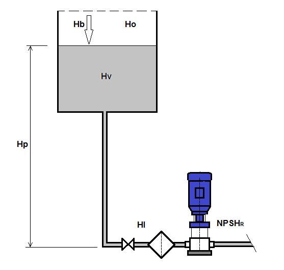
3.5Calculation of NPSHa
Calculation NPSHa > NPSHr + 0,5
Check if cavitation can be expected.
Hb + Ho + Hp - HV - Hi > NPSHr + 0,5
Hb = barometric pressure in mwc
Ho = over pressure (in case of closed tank) in mwc
Hp = suction lift in mwc
Hv =- vapour pressure in mwc
Hl = friction loss in pipe work and accessories in mwc
NPSHr = net positive suction head of the pump
0.5 = safety factor
Table 8: Calculation NPSHa
Atmosferic pressure + 10.3 mwc
Overpressure in degassing tank + …… .mwc
Positive height of degassing tank or vessel + ……. mwc
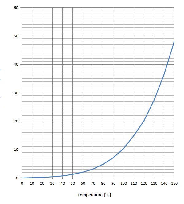
Vapour pressure of feed water (see table)in degassing tank in case of boiler feed - ……. mwc
Loss of pressure in suction piping and strainer - ……. mwc
Safety factor - 0.5 mwc
NPSHr at duty point (see pumpcurve) - ……. mwc
Minimal positive pressure x mwc
If 'x' is positive there is no cavitation to be expected
If 'x' is negative cavitation can be expected, to avoid this the low NPSH impeller could solve this problem. Otherwise one of the other values can be changed so the outcome will be positive.
1.All motor dimensions are only valid for Wonder motors with efficiency class IE3.
DPV C F Cast iron flange
Norm: Fits on EN 1092-1/1092-2
Size: NW80
Pressure Class: PN16
DPV (S) F Loose plate flange
Cataphoric coated loose plate flange
Norm: Fits on EN 1092-1/1092-2
Size: NW80
Pressure Class: PN16
Option: Loose plate flange cast SS1.4308
DPV (S) F Loose plate flange
Cataphoric coated loose plate flange
Norm: Fits on EN 1092-1/1092-2
Size: NW80 interchangeable range 45
Pressure Class: PN16
Option: Loose plate flange cast SS1.4308
20130943
20130950
4.12 DPV(C/S) 60 B - 60Hz - 2 pole - DIN
Table 29: coupled motor construction type; V1
Modelpressure class
PowerMotor dimensions1
60/1-1PN107,52881973001009577134
60/1 113402233501140607211
60/2-2 153402233501218685225
60/2 18,53402233501218685242
60/3-2 223602343501411763284
60/3PN16304003404001433763355
60/4-2 304003404001511841359
60/4PN25374003404001511841378
60/5-2 454503654501629919453
60/5 454503654501629919453
1.All dimensions are only valid for Cantoni motors with efficiency class IE3. Motor power ≥ 30kW: All dimensions are only valid for Wonder motors with efficiency class IE3. *Dimensions of IE3-v2 motor. DPV(C/S)F
DPV C F Cast iron flange
Norm: Fits on EN 1092-1/1092-2
Size: NW100
Pressure Class:PN16
DPV C F Cast iron flange
Norm: Fits on EN 1092-1/1092-2
Size: NW100
Pressure Class:PN25/40
DPV (S) F Loose plate flange
Cataphoric coated loose plate flange
Norm: Fits on EN 1092-1/1092-2
Size: NW100
Pressure Class: PN16
Option: Loose plate flange cast SS1.4308
DPV (S) F Loose plate flange
Cataphoric coated loose plate flange
Norm: Fits on EN 1092-1/1092-2
Size: NW100
Pressure Class: PN25/40
Option: Loose plate flange cast SS1.4308
DPV (S) F Stainless steel flanges
DPVF: SS 1.4308 / DPVSF: SS 1.4408
Norm: Fits on EN 1092-1/1092-2
Size: NW100
Pressure Class: PN40
20120677
20110027
20101155
20120679
20120680
4.13 DPV(C/S) 60 B - 60Hz - 4 pole - DIN
Table 30: coupled motor construction type; V18
Modelpressure class PowerMotor dimensionsDPV(C/S)F
[kW]E1 [mm] E2 [mm] P [mm] F1 [mm] F2 [mm] Mass [kg]
60/2PN103200155927565101
60/3 4223166958643115
20120682
Table 31: coupled motor construction type; V1
Modelpressure class PowerMotor dimensions1
DPV(C/S)F
[kW]E1 [mm] E2 [mm] P [mm] F1 [mm] F2 [mm] Mass [kg]
60/4PN105,52601903001211811155
60/5 5,52601903001289889159
60/6 7,52601903001402967183
60/7 7,526019035015101075201
20120681
1.All motor dimensions are only valid for Wonder motors with efficiency class IE3 (motor power ≥0,75kW).
DPV C F Cast iron flange
Norm: Fits on EN 1092-1/1092-2
Size: NW100
Pressure Class: PN16
DPV (S) F Loose plate flange
Cataphoric coated loose plate flange
Norm: Fits on EN 1092-1/1092-2
Size: NW100
Pressure Class: PN16
Option: Loose plate flange in SS 1.4308
20120677
20101155
4.14 DPV(C/S) 85 B - 60Hz - 2 and 4 pole - DIN
Table 32: coupled motor construction type; V1
Modelpressure class PowerMotor dimensions1 DPV(C/S)F [kW]E1 [mm] E2 [mm] P [mm] F1 [mm] F2 [mm] Mass [kg]
85/1-1PN10113402233501204671223
85/1 153402233501204671241
85/2-2 18,53402233501313780266
85/2-1 223602343501428780302
85/2 304003404001450780390
85/3-2PN16/25/40304003404001559889399
85/3-1 374003404001559889413
85/3 454503654501599889541
85/4-2 454503654501708998543
20091237
1.All dimensions are only valid for Cantoni motors with efficiency class IE3. Motor power ≥ 30kW: All dimensions are only valid for Wonder motors with efficiency class IE3.
Table 33: coupled motor construction type; V1, 4 pole
Modelpressure class PowerMotor dimensions1 DPV(C/S)F
[mm] E2 [mm] P [mm] F1 [mm] F2 [mm] Mass [kg]
85/3-1PN105,52601903001259859185
85/3 5,52601903001259859198
85/4-2 5,52601903001368968208
1.All motor dimensions are only valid for Wonder motors with efficiency class IE3.
DPV C F Cast iron flange
Norm: Fits on EN 1092-1/1092-2
Size: NW100
Pressure Class:PN16
DPV C F Cast iron flange
Norm: Fits on EN 1092-1/1092-2
Size: NW100
Pressure Class:PN25/40
DPV (S) F Loose plate flange
Cataphoric coated loose plate flange
Norm: Fits on EN 1092-1/1092-2
Size: NW100
Pressure Class: PN16
Option: Loose plate flange and baseplate in cast SS1.4308
DPV (S) F Loose plate flange
Cataphoric coated loose plate flange
Norm: Fits on EN 1092-1/1092-2
Size: NW100
Pressure Class: PN25/40
Option: Loose plate flange and baseplate in cast SS1.4308
20090643
20090642
20090643
4.15 DPV(C/S) 125
B - 60Hz - 2 pole - DIN
Table 34: coupled motor construction type; V1 20150648
Modelpressure class PowerMotor dimensions1
125/1PN10223602343501387739317337
125/2-2 304003404001539869426445
125/2PN16454503654501579869505524
1.All dimensions are only valid for Cantoni motors with efficiency class IE3. Motor power ≥ 30kW: All dimensions are only valid for Wonder motors with efficiency class IE3.
DPV C F with cast iron flange
Norm: Fits on EN 1092-1/1092-2
Size: NW125
Pressure Class: PN16
DPV C F with cast iron flange
Norm: Fits on EN 1092-1/1092-2
Size: NW125
Pressure Class: PN25
DPV (S) F with loose plate flange
Cataphoric coated loose plate flange
Norm: Fits on EN 1092-1/1092-2
Size: NW125
Pressure Class: PN16
Option: Loose plate flange in cast SS1.4308
DPV (S) F with stainless steel flanges
Norm: Fits on EN 1092-1/1092-2
Size: NW125
Pressure Class: PN25
20150646
20150647
20150646
20150647
5Seals
5.1Mechanical seal option specifications
15RMG12-G606U3 U3 X4 GG
22H7N Q1 A X4 GG
404MC Q1 Q1 E GG
414MC Q1 A E GG
TuCTuCHNBRPN25(PN16)-20/+120(140)°CHNBR
SiCCaHNBRPN40(PN25)-20/+120(140)°CHNBRHP/HT ●
SiCSiCEPDMPN40(PN25)-20/+120(140)°CEPDMHP/HT
SiCCaEPDMPN40(PN25)-20/+120(140)°CEPDMHP/HT
424MC Q1 Q1 V GG SiCSiCFPMPN40(PN25)-20/+120(140)°CFPM HP/HT
434MC Q1 A V GG SiCCaFPMPN40(PN25)-20/+120(140)°CFPM HP/HT ●
50RMG12-G6A Q7 E GG
51eRMG12-G6A Q7 E GG Y10
52eRMG12-G6A Q7 V GG Y10
CaeSiCEPDMPN25(PN18)-20/+120(140)°CEPDM 559236 ●●
CaeSiCEPDMPN25(PN18)-20/+120(140)°CEPDM
CaeSiCFPMPN25(PN16)-20/+120(140)°CFPM ● 53eMG12-G6B Q7 E GG Y10 WACaeSiCEPDMPN25-20/+100°CEPDM
54MG12-G6B Q7 E GG WA
55RMG12-G6B Q7 V GG
56eRMG12-G6B Q7 V GG Y10
57MG1-G6B Q7 E GG WA
CaeSiCEPDMPN25-20/+100°CEPDM
CaeSiCFPMPN25-20/+120°CFPM
CaeSiCFPMPN25-20/+120°CFPM
CaeSiCEPDMPN25-20/+100°C
58eMG12-G6Q7 Q7 E GG Y10 WAeSiCeSiCEPDMPN18-20/+100°CEPDM
59MG12-G6Q7 Q7 E GG WAeSiCeSiCEPDMPN18-20/+100°CEPDM
60RMG12-G6Q7 Q7 V GG eSiCeSiCFPMPN18-20/+120°CFPM
61eRMG12-G6Q7 Q7 V GG Y10eSiCeSiCFPMPN18-20/+120°CFPM
65eRMG12-G6U3 U3 V GG Y10TuCTuCFPMPN18-20/+120°CFPM
66eMG12-G6Q7 Q7 V GG Y10eSiCeSiCFPMPN20-20/+60°CFPM ●
ATTENTION
Seal dimensions according to EN24960
6Motors and motor options
6.1General
The standard DPmotors are produced conform the latest technical design, and comply with the international standards and EU directives regarding safety measures.
The motors can be specified as:
• standard IE3 >= 0,75kW.
• T.E.F.C. (totally enclosed fan cooled) Squirrel cage.
The standard Duijvelaar pompen motors are specially designed to drive the pump. When a standard motor has to be installed (or a special motor to fulfil the applications requirement, like explosion proof, high efficiency) a special bearing housing must be installed to relieve the motor of the axial force created by the pump.
ATTENTION
This option is not applicable for pump model DPVM.
ATTENTION
Only a motor with a standard key can be installed with a thrust bearing housing.
ATTENTION
There is no need to change the motor stool of the pump. The bearing flange can be mounted on the standard motor stool of the pump.
1.Note: The indication of the material designations to ASTM / AISI is not binding
8.1.3Sectional drawing DPVCF 2/4/6 B
Figure 33: Sectional drawing DPV(S) 2/4/6 B
8.1.4Sectional drawing DPV(S) 2/4/6 B
34: Sectional drawing DPV(S) 2/4/6 B
Figure
20080766-H
8.1.5Sectional drawing DPVCF 10 B
Figure 35: Sectional drawing DPVCF 10 B
8.1.6Sectional drawing DPV(S) 10 B
Figure 36: Sectional drawing DPV(S) 10 B
8.1.7Sectional drawing DPV(S) 15 C
Figure 37: Sectional drawing DPV(S) 15 C
20210209
8.1.8Sectional drawing DPVF(S) 25 B
Figure 38: Sectional drawing DPVF(S) 25 B
8.1.9Sectional drawing DPVF(S) 40, 60 B
Figure 39: Sectional drawing DPVF(S) 40, 60 B 20170642
8.1.10Sectional drawing DPVCF 85 B
Figure 40: Sectional drawing DPVCF 85 B
8.1.11Sectional
drawing DPV(S)F85 B
Figure 41: Sectional drawing DPV(S)F 85 B
8.1.12Sectional drawing DPV(S)F125 B
Figure 42: Sectional drawing DPV(S)F 125 B
9Medium
handled
9.1Medium handled
duijvelaar pompen
Kalkovenweg 13
2401 LJ Alphen aan den Rijn
The Netherlands
t +31 172 48 83 88
dp@dp.nl www.dp.nl
01/2025
97004456 O
Subject to modifications. Digital alteration, publication or distribution of the content of this document without prior notice is strictly prohibited. Permission for use, copying and distribution of this document as published by DP-Pumps is granted on the condition that no part of the document is used for information or commercial purposes outside of the DP-Pumps organisation or one of its recognised dealerships.