HONDA EU1000i
GENERATOR
HONDA EU1000i Generator
Generator Model
Rated (Surge) Watts
Output Volts
DC Amps
Engine Model
EU1000i
900 (1000)
120 AC/12 DC
8
GXH50-GCAL
IDENTIFICATION These generators are direct drive, brushless, 60 Hz, single-phase units with both 120VAC and 12VDC output available from panel-mounted receptacles. The generator serial number is located on the outside of the side cover, just below the engine switch knob and the recoil starter handle grip. Refer to Figs. HA151, HA152 and HA153 to view the generator components.
WIRE COLOR CODES The following color-code abbreviations are used to identify the generator wiring in this series: Bl – Black R – Red Y – Yellow Gr – Gray
Bu – Blue G – Green Br – Brown P – Pink
W – White Lb – Light blue Lg – Light green O – Orange
A wire with a slash-separated ID is a two-color wire; (e.g. R/W is a red wire with a white tracer stripe).
GENERATOR REPAIR TROUBLESHOOTING Before testing any electrical components, check the integrity of the terminals and connectors. While testing individual components, also check the wiring integrity. Resistance readings may vary with temperature and test equipment accuracy. For access to the components listed in this Troubleshooting section, refer to Fig. HA151 and the later Disassembly section. All operational testing must be performed with the engine running at its governed no-load speed of 5400-5600 RPM, unless specific instructions state otherwise. Always load test the generator after repairing defects discovered during troubleshooting. 1. To troubleshoot the generator, start the engine and verify the following: a. ECO switch OFF, b. Overload Indicator Light OFF,
172
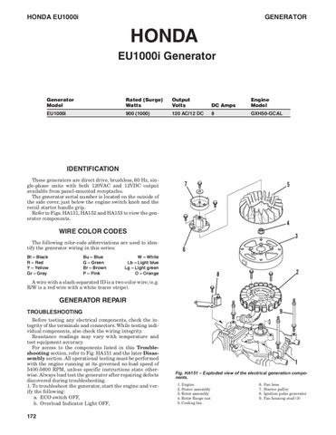
Fig. HA151 – Exploded view of the electrical generation components. 1. Engine 2. Stator assembly 3. Rotor assembly 4. Rotor flange nut 5. Cooling fan
6. 7. 8. 9.
Fan boss Starter pulley Ignition pulse generator Fan housing stud (3)