
High-Tech Alarm System with Raspberry Pi

#
#Version 5.2
#This version has a 2 min entrance and exit dalay


#This version of the software works with the RFID reader, #and the key switch


#This software is for use with Rev 4.5 of the PCB #


#sudo apt-get install alsaaud*

#sudo pip3 install rpi_lcd
#sudo apt-get install -y espeak

import RPi.GPIO as GPIO import time import os import threading from rpi_lcd import LCD
lcd=LCD()


#Broadcom numbering scheme


GPIO.setmode(GPIO.BCM)


William Pretty
booksbooks
● William Pretty
Building a High-Tech Alarm System with Raspberry Pi
● This is an Elektor Publication. Elektor is the media brand of Elektor International Media B.V.
PO Box 11, NL-6114-ZG Susteren, The Netherlands
Phone: +31 46 4389444
● All rights reserved. No part of this book may be reproduced in any material form, including photocopying, or storing in any medium by electronic means and whether or not transiently or incidentally to some other use of this publication, without the written permission of the copyright holder except in accordance with the provisions of the Copyright Designs and Patents Act 1988 or under the terms of a licence issued by the Copyright Licencing Agency Ltd., 90 Tottenham Court Road, London, England W1P 9HE. Applications for the copyright holder's permission to reproduce any part of the publication should be addressed to the publishers.
● Declaration
The author, editor, and publisher have used their best efforts in ensuring the correctness of the information contained in this book. They do not assume, and hereby disclaim, any liability to any party for any loss or damage caused by errors or omissions in this book, whether such errors or omissions result from negligence, accident or any other cause. All the programs given in the book are Copyright of the Author and Elektor International Media. These programs may only be used for educational purposes. Written permission from the Author or Elektor must be obtained before any of these programs can be used for commercial purposes.
● British Library Cataloguing in Publication Data
A catalogue record for this book is available from the British Library
● ISBN 978-3-89576-551-3 Print
ISBN 978-3-89576-552-0 eBook
● © Copyright 2023: Elektor International Media B.V.
Prepress Production: D-Vision, Julian van den Berg
Elektor is the world's leading source of essential technical information and electronics products for pro engineers, electronics designers, and the companies seeking to engage them. Each day, our international team develops and delivers high-quality content - via a variety of media channels (including magazines, video, digital media, and social media) in several languages - relating to electronics design and DIY electronics. www.elektormagazine.com
● 4
Contents ● 5 Contents Chapter 1 • Introduction to Alarm Systems ................................ 7 Alarm System Sensors - Door / Window Contact ............................. 7 Motion Detectors ................................................... 8 Glass Break Sensor ................................................. 9 Fire Alarm Sensors - Heat Detectors ..................................... 9 Fire Alarm Sensors - Smoke Alarms .................................... 11 Access Control ................................................... 14 Block diagram of the alarm system 16 References ...................................................... 16 Chapter 2 • Hardware ............................................... 17 Chapter 3 • Human Interface ......................................... 22 LCD Display 22 Human Interface - Voice Output ....................................... 29 Human Interface - RFID Card Reader 30 Chapter 4 • Software ................................................ 33 Version 5.1 33 Version 5.2 ...................................................... 40 Chapter 5 • Printed Circuit Board....................................... 47 Assembly ....................................................... 47 Printed Circuit Board ............................................... 51 Chapter 6 • Alarm System Wiring ...................................... 57 Zone Test Switches ................................................ 57 Constructing the Harnesses 59 Testing the Harnesses .............................................. 62 Wiring the Sensors 63 Chapter 7 • Planning your Alarm System................................. 70 Step 1 – The Walk-about 71 Typical Four-Bedroom House ......................................... 71 Typical Pub or Restaurant 76 Commercial Office Space ............................................ 79
Building a High-Tech Alarm System with Raspberry Pi ● 6 Laboratory ...................................................... 81 Chapter 8 • Future Enhancements ...................................... 83 Running Alarm Program from Boot ..................................... 83 Running Raspberry Pi from 12 volts 84 Water / Moisture Detector ........................................... 87 Adding a Door Solenoid 88 Links ......................................................... 92 Appendix.......................................................... 93 Bill of Materials ................................................... 93 Software 94 Schematics..................................................... 112
Chapter 1 • Introduction to Alarm Systems
In this chapter we will discuss the basic components of any alarm system. All alarm systems have two basic functions. First, they monitor their environment looking for a change such as a door or window opening or someone moving about in the room. The second function of the system is to alert the human to this change. Our alarm system uses a scanning type software to detect intruders. We will use the 'standard' guard dog as an analogy. In a scanned type of system, the guard dog paces back and forth at the fence looking out for either an intruder or someone that it recognizes. In our design, if you have an alarm key, you can disarm the system and enter. In an interrupt driven system, the dog is asleep until it hears an intruder (or you). It then wakes up and deals with the situation. I have chosen the scanning method because in my opinion the software is easier to write and explain. It can scan all eight zones in about one second.
You don't have to be an electrical engineer to install an alarm system, just a good carpenter, painter, and plasterer! I'm not by the way so I'll leave hiding wires up to you.
Also, because our alarm system runs on 12 volts, you don't have to be a licensed electrician to install it. If you can plug in a wall adapter, you can build and test this alarm system.
Alarm System Sensors - Door / Window Contact
The simplest and one of the most common sensors is the door / window contact. This sensor consists of a magnet which is installed on the moving part of the door or window. This magnet holds a switch closed. The switch portion of the sensor is attached to the door or window frame. Figure 2 shows what is inside a typical sensor of this type.


● 7
Figure 1-1. Door / Window Contact Schematic
Figure 1-2. Door / Window Contact
Building a High-Tech Alarm System with Raspberry Pi
Motion Detectors


The next most common sensor is the PIR or Passive Infra-Red detector. This sensor measures the ambient temperature of the room and waits for a change in the ambient. Often called a 'blip'.
Simple PIR sensors tend to be fooled by large pets (like your guard dog). For that reason, they have a "pet" setting which ignores any object less than 30 pounds, which is moving close to the floor. More modern (expensive) sensors also have a mmWave sensor built in which tends to reduce false alarms and makes the sensor harder to fool. The dual sensor is about three times the price of a simple PIR detector and communicates with the panel with the same contact switch arrangement.
● 8
Figure 1-3. How PIR Sensor works
Figure 1-4. PIR Motion Sensor
Glass Break Sensor
Another type of sensor is the glass break sensor. This type of sensor is commonly used by shop owners to help detect vandalism. This sensor uses a microphone to 'listen' for the sound of breaking glass.
The system consists of a sensitive microphone, an amplifier, and a filter (usually digital signal processing). The output of this filter is connected to a detector circuit which activates the alarm system contacts when the sound of breaking glass is 'heard' by the microphone.

Fire Alarm Sensors - Heat Detectors
There are two basic types of heat detectors, mechanical and electronic. The electronic type of detector uses a thermistor as the sense element. A thermistor is type of resistor that changes its value based on the ambient temperature. In practice two thermistors are used. One resistor is exposed to the ambient air and the other is partially sealed from the surrounding air. A fast rise in the air temperature, for example from an open flame, is sensed by the resistor which is exposed to the surrounding air. The resistor changes its value, and an alarm is triggered. A slow rise in temperature, from a smoldering fire, is sensed by both resistors and again an alarm is triggered.

Chapter 1 • Introduction to Alarm Systems ● 9
Figure 1-5. How Glass Break Sensor works
Figure 1-6. Typical Glass Break Sensor
Building a High-Tech Alarm System with Raspberry Pi
There are two types of mechanical heat detector, bimetallic and pneumatic.
A bimetallic heat detector contains a metallic strip consisting of two different metals bonded together. When heat reaches the strip, it bends until the contacts are closed and an alarm condition is signaled.


Another type of heat detector is the fixed temperature heat detector. As the name suggests, the sensor is set to trigger at a specific temperature. The trigger temperature is usually marked on the outside of the device. The device shown below is a combination of ROR and fixed temperature device.
ROR heat detectors may not respond to smoldering fires. For that reason, a fixed element is also included in the device, in order to detect this type of fire. The small metal disk in the center of the unit is part of fixed element. In the bottom view, you can see a tube in the center of the device. This tube is filled with a wax like substance which is designed to melt at a preset temperature. In this case 136F or 67C. The small, pointed tube to the right of the large tube is the vent for the rate of rise detector.
●
10
Figure 1-7. Bimetallic Heat detector © Hochiki
Figure 1-8. Pneumatic Heat sensor © Hochiki
Heat detectors are useful in areas such a garages, kitchens, or workshops. Where a certain amount of smoke or fumes is 'normal' but would trigger a smoke alarm. This is due to dust or smoke particles in the air.
Fire Alarm Sensors - Smoke Alarms
There are three types of smoke alarms. These are photoelectric, ionization and a combination of both. The ionization type smoke detector uses a small radioactive source, usually americium-241. The detector consists of two positive and negative charged electrodes inside an ionization chamber.


Chapter 1 • Introduction to Alarm Systems ● 11
Figure 1-9. Fixed Temperature / ROR Alarm
Figure 1-10. Bottom View
Building a High-Tech Alarm System with Raspberry Pi
The radioactive alpha particles cause a small current to flow between the two electrodes. This current is sensed by the electronics of the detector. If smoke particles enter the chamber thru the bug screen, then the current flow is interrupted.
Once enough smoke has entered the chamber, the current change is detected, and an alarm condition is sent to the alarm panel. This type of detector is called a four-wire detector, because two wires are used to power the electronics and two are used for the alarm contacts.
The other type of smoke detector is the photoelectric based detector. There are two types of photoelectric smoke detector. The first type we will be discussing is the scattering type detector.
There is no direct path between the light source and the light receiver. This is due to a series of baffles inside the detection chamber.
● 12 – – – – – – –+ + + + + + + + – – – – – – –+ + + + + + + + – – – – – – –+ + + + + + + + – – – – – – –+ + + + + + + + – – – – – – –+ + + + + + + + – – – – – – –+ + + + + + + + – – – – – – –+ + + + + + + + – – – – – – –Electrodes Insect Grid Radioactive Source Chamber Cover Electronics Smoke Radioactive Source
1-11.
Smoke
Figure
Ionization
Detector
– – – – – – –+ + + + + + + + – – – – – – –+ + + + + + + + – – – – – – –+ + + + + + + + – – – – – – –+ + + + + + + + – – – – – – –+ + + + + + + + – – – – – – –+ + + + + + + + – – – – – – –+ + + + + + + + – – – – – – –Electrodes Insect Grid Radioactive Source Chamber Cover Electronics Smoke Radioactive Source
Figure 1-12. Smoke enters the detector
Infra Red Light Emitter
Infra Red Light Emitter
Infra Red Light Emitter
Infra Red Light Detector
Infra Red Light Detector
Infra Red Light Detector
Lightproof Chamber Cover
Lightproof Chamber Cover
Lightproof Chamber Cover
These baffles are arranged is such a way as to allow smoke to enter the chamber, while keeping light out.
Smoke Smoke
Smoke Smoke
Smoke Smoke
Scattered IR
Scattered IR
Scattered IR
Smoke enters the chamber and 'scatters' the light from the transmitter. This light is then detected by the photo receiver. Once a sufficient mount light is detected, an alarm condition is sensed.
The second type of photoelectric detector allows smoke to obscure the infra-red beam. When this happens an alarm sounds.
Chapter 1 • Introduction to Alarm Systems ● 13
Figure 1-13. Photoelectric Detector
Figure 1-14. Smoke Enters Chamber
Figure 1-15. Light Scattered by Smoke
It is worth mentioning that these types of optical detector use infra-red LEDs, so as to reduce false alarms due to ambient light entering the chamber.

Access Control
The simplest type of access control is the key switch, and it is the type I am using in the design of this alarm system. The switch that I am using takes a round key and is an on-offon switch. When the switch is rotated left or right, the common contact is connected to one of the two other terminals. The key is only removable in the center or off position.
A keypad can also be connected to the alarm panel. The pad is 4 x 3 matrix of keys. This matrix is scanned by a microprocessor and an ASCII character is sent to the panel when a button is pushed. In some cases, the microprocessor is part of the keypad, in others it is on the main board of the alarm system. For our system, we would have to use an Arduino to scan the keys. I decided to keep the design simple and use a key switch as the standard access control method.
Building
High-Tech
● 14
a
Alarm System with Raspberry Pi
Figure 1-16. Light Obscured by Smoke
Figure 1-17. Key Switch
A good alternative to the keypad is an RFID card reader. This reader is easily connected to the Raspberry Pi via one of its USB ports. The card reader looks like a keyboard to the Pi and sends an ASCII string to the system. The string consists of the serial number programed onto the card, followed by a carriage return. In this way it mimics the user typing on a keyboard. The system then checks a database (text file) of valid serial numbers. If the number is valid it takes the appropriate action.


Chapter 1 • Introduction to Alarm Systems ● 15
Figure 1-18. Alarm panel Keypad
Figure 1-19. RFID Card Reader
Building a High-Tech Alarm System with Raspberry Pi

Block diagram of the alarm system
Figure 1-20 is a block diagram of the alarm system. A Raspberry Pi Model 3 was used to write and debug both the hardware and the software. The model 3 has all of the computing power required to do this. The Human Interface section shows a keyboard, monitor and mouse connected to the Raspberry Pi. These devices are only required for debugging purposes and can be removed once the system is operational. The alarm system human interface consists of a speaker or speakers so that the alarm system can ‘talk’ to the world. A two-line LCD is used to communicate the status of the alarm system to the user. An optional RFID card reader can be plugged into one of the Raspberry Pi’s USB ports. There is also a key switch (not shown) which is connected to one of the alarm system’s inputs and can be used to arm and disarm the system under certain conditions.
The alarm panel main board has 8 burglar alarm zones and two fire alarm zones which can be connected to various sensors and detectors. The alarm panel can be connected to a 12-volt LED for debugging purposes or a 12-volt siren once the panel has been debugged and is read to deploy. The alarm panel and sensors are powered by a 12 volt DC power cube which is connected to the AC mains supply. This version uses a 5-volt DC adapter to power the Raspberry Pi.
References
• www.safelincs.co.uk/smoke-alarm-types-ionisation-alarms-overview/
• www.electronicsforu.com/technology-trends/smoke-detectors-fire-alarms-guide/
• medium.com/@chuanjerlim/confession-of-a-photoelectric-smoke-alarm3be8bbd65af9/
• www.hochikieurope.com/products/
• www.hochikiamerica.com/
●
16
Figure 1-20. Block diagram of the alarm system.
Chapter 2 • Hardware
The main component of the alarm system is the comparator. The comparator we are using is an LM2903P. The LM2903P is a dual comparator in an 8-pin dip package with open drain outputs.
A comparator is a special purpose amplifier which has two analog inputs, called V+ and V-. The comparator outputs a digital signal Vo, which indicates which input is larger than the other.

The output is the following: Vo = 1 if V+ > VVo = 0 if V- > V+
The following figure shows the zone circuit in 'normal' operation.
Resistors R1 and R2 form a voltage divider which applies approximately two volts to the inverting input of the comparator. R3, R4 and the end of line resistor (EOL) form another voltage divider. This divider is connected to the noninverting input of the comparator. When the alarm contact is closed (no alarm), approximately three point four volts will be measured at the noninverting input to the comparator. This means that the noninverting input is higher than the inverting one. This causes the output to remain high. (The output of the LM2903P has an open drain output, so the internal GPIO pull up resistor can cause the input to be pulled high.)
Chapter 2 • Hardware ● 17
Figure 2-1. Open Detection
Building a High-Tech Alarm System with Raspberry Pi
When an alarm is triggered, or the wire is cut, R3 pulls the input low. Now the noninverting input is lower than the inverting input. The output transistor is turned on and the output is pulled low.

The following figure shows what happens if a burglar attempts to short the alarm contacts. The LM2903P is a dual comparator so, we will use the second half to sense this condition. The following figure shows the result of this condition.
In this case resistors R5 and R6 form a voltage divider which is connected to the noninverting input of the comparator. This results in approximately nine volts being applied to the input. If there is no short, then there is three point four volts applied to the inverting input. This means that the inverting input is lower than the noninverting input. So, the output is turned off and the internal pullup resistor pulls the input high. If a burglar attempts to short out the switch, they will also short out the end of line resistor. This results in twelve volts being applied to the inverting input. Now the inverting input is higher than the noninverting input. This causes the output of the comparator to go low and an alarm condition occurs.
The LM2903P is an open drain output device. This allows us to connect the two outputs together in a wired 'OR' configuration. This means that if either a short circuit OR an open one occurs, the input to the Raspberry Pi will be pulled low. The cathode of a red LED is also connected to the outputs. The anode is connected to three point three volts thru a series resistor. When either output goes low, the LED turns on to indicate that there is an alarm condition on that zone.
●
18
Figure 2-2. Short Detection
The alarm system consists of eight zones, so the circuitry we have just discussed is repeated eight times.
There are two special zones called 'fire zones' these zones are intended to be connected to a two-wire heat rise detector or the normally open contacts of a four-wire smoke detector. The contacts on this type of detector operate the opposite to other four wire detectors. The contacts of a two-wire detector are normally open and close to indicate an alarm. The LM2903P is a dual comparator, so the alarm system can monitor two fire zones.
One terminal of the fire zone 1 detector is connected to pin 1 of J16. The other terminal is connected to pin 2.
One terminal of the fire zone 2 detector is connected to pin 1 of J17. The other terminal is connected to pin 2 of J17.
The contacts are normally open, so resistors R24 and R26 pull the inverting input to ground. This makes the inverting input lower than the noninverting input which is connected to the 9V reference. The output transistor is turned off and the internal pullup resistor pulls the output high. (Vo = 1 if V+ > V-)

Chapter 2 • Hardware ● 19
Figure 2-3. Fire Zones
Building a High-Tech Alarm System with Raspberry Pi
When excessive heat or smoke is detected, the contacts close, and the inverting input is pulled up to 12V. This makes the inverting input higher than the noninverting input. The output transistor is turned on and the output is pulled low. (Vo = 0 if V- > V+)
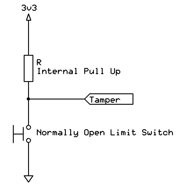
The next zone is a special zone called "Tamper". This zone input is connected to a normally open limit switch. The switch is connected to ground and is held closed by the lid of the alarm system. When the system is armed and the cover is removed, the internal pullup resistor pulls the GPIO pin high, and an alarm is triggered.
External power is supplied to the board via connectors J5 and J6. A twelve-volt four-amp power cube is connected to J6, and a 12-volt SLA (Sealed Lead Acid) battery is connected to J5. These two sources are connected by power diodes D1 and D2. The board derives its twelve-volt power from F2, which
is a three-amp PTC fuse. A PTC fuse is like a solid-state circuit breaker. The letters PTC stand for Positive Temperature Coefficient. This means that as more current flows thru the device it heats up and the resistance goes up, until finally the resistance goes very high. This is called the avalanche point. In this case the point is three amperes.
You may be wondering why I specified a four-amp power supply. This is because I always try to over specify the capacity of the power supply so as not to over tax the supply by running it at its maximum capacity. As for the battery. If you want the system to be able to run for four hours on battery power, then you will need a twelve-volt, twelve-amp hour battery as a minimum. SLA batteries are usually discharged at a one third-C rate. That is, one third of their capacity. Unlike some commercial alarm panels, our design does not include a battery charging circuit. Therefore, the battery should be checked from time to time and recharged if necessary, using a constant voltage charger. Such as an automotive battery charger.
●
20
Figure 2-4. Tamper Switch Circuit
A siren which draws up to two amps DC can be connected to J4. An opto-isolator which contains a power MOSFET as its output is used to switch the siren. Note that the MOSFET can only switch DC loads. That is why J4 is connected to the onboard twelve-volt supply. The MOSFET is only protected by the three-amp fuse, so care should be taken when selecting the siren or other load. If more than two amps DC or an AC load such as lighting is connected to the output, then a twelve-volt mechanical relay should be connected to the output.

In this chapter we discussed the various circuits which allow the alarm panel to communicate with the sensors and indicators connected to the alarm system. In the next chapter we will discuss how the alarm panel communicates with humans in the outside world. Various input and output devices will be discussed.

Chapter 2 • Hardware ● 21
Figure 2-5. System Power
Figure 2-6. Alarm Output
Building a High-Tech Alarm System with Raspberry Pi
This book discusses the basic components of any alarm system.
All alarm systems have two basic functions. First, they monitor their environment looking for a change such as a door or window opening or someone moving about in the room. Second, they alert the legal owner or user to this change. The system described in this book uses a scanning type software to detect intruders. It behaves like a guard dog, pacing up and down the fence line on the lookout for either an intruder or a familiar person. If you have an alarm key, you can disarm the system and enter.
With the scanning method, the software is easy to write and explain. It can scan eight alarm zones plus two special fire zones in about one second.
You don’t have to be an electrical engineer to install an alarm system, just a decent carpenter, painter, and plasterer! Because this alarm system runs on 12 volts, you don’t have to be a licensed electrician either to install it. The alarm system presented here uses Python software on the Raspberry Pi combined with some elementary electronic circuits. The code described in the book, as well as CAD files and a bill of materials for the alarm panel, are available for free downloading. The book provides the reader with examples of typical configurations coming straight from the author‘s experience. After reviewing the hardware components typically used in common alarm systems, the author shows how to plan one yourself.
To implement a modular alarm, no matter if it is for a single house or for a business or restaurant, the book shows how to skillfully combine a Raspberry Pi with small auxiliary electronic circuits. These are not installation instructions but food for thought that will enable readers to find a solution to their needs.
William (Bill) Pretty began his career with a telecom company. He pursued a career in aviation and then joined the Ontario Center for Microelectronics. Bill left there for a 30-year career in the military as a civilian contractor. He was a guest presenter at the Western Canada Technical Conference. He started his own company in 2010, providing support in the form of R&D, to law enforcement and private security agencies.

Elektor International Media BV www.elektor.com
booksbooks
Credits: Dellas Wreikkinen