

Easy and Affordable Digital Signal Processing
● Dogan Ibrahim Ahmet Ibrahim● This is an Elektor Publication. Elektor is the media brand of Elektor International Media B.V.
PO Box 11, NL-6114-ZG Susteren, The Netherlands
Phone: +31 46 4389444
● All rights reserved. No part of this book may be reproduced in any material form, including photocopying, or storing in any medium by electronic means and whether or not transiently or incidentally to some other use of this publication, without the written permission of the copyright holder except in accordance with the provisions of the Copyright Designs and Patents Act 1988 or under the terms of a licence issued by the Copyright Licencing Agency Ltd., 90 Tottenham Court Road, London, England W1P 9HE. Applications for the copyright holder's permission to reproduce any part of the publication should be addressed to the publishers.
● Declaration
The author, editor, and publisher have used their best efforts in ensuring the correctness of the information contained in this book. They do not assume, and hereby disclaim, any liability to any party for any loss or damage caused by errors or omissions in this book, whether such errors or omissions result from negligence, accident or any other cause. All the programs given in the book are Copyright of the Author and Elektor International Media. These programs may only be used for educational purposes. Written permission from the Author or Elektor must be obtained before any of these programs can be used for commercial purposes.
● British Library Cataloguing in Publication Data
A catalogue record for this book is available from the British Library
● ISBN 978-3-89576-567-4 Print
ISBN 978-3-89576-568-1 eBook
● © Copyright 2023: Elektor International Media B.V.
Editor: Jan Buiting
Prepress Production: D-Vision, Julian van den Berg
Elektor is the world's leading source of essential technical information and electronics products for pro engineers, electronics designers, and the companies seeking to engage them. Each day, our international team develops and delivers high-quality content - via a variety of media channels (including magazines, video, digital media, and social media) in several languages - relating to electronics design and DIY electronics. www.elektormagazine.com
Practical Audio DSP Projects with the ESP32
Digital Signal Processing (DSP) is the process of capturing, analyzing, and manipulating analog or digital signals by any type of digital processor including digital computers and microcontrollers.
The theory of DSP is quite complex and requires a good understanding of higher-level mathematics and discrete time systems. Students new to DSP are usually taught the theory in great detail with very few or no practical applications. For example, in many cases a student can derive complex equations for digital filters or Fast Fourier Transforms (FFT) but is unable to implement a simple digital filter in real life. Some institutions use tools such as MATLAB to derive the coefficients of digital filters and then to simulate the behavior of these filters on a PC. Although simulation can be an invaluable tool in teaching, it is never the same as real-time or real-life implementations.
The aim of this book is to teach the basic principles of DSP and to introduce DSP from a practical point of view using the bare minimum of mathematics. The level of discrete-time systems theory is sufficient to permit implementing DSP applications in real time. The emphasis of the book is on practical aspects of DSP such as design issues and real-time implementation issues. The practical implementation is described using the highly popular and widely available, low-cost, ESP32 DevKitC microcontroller development board enabling readers to easily and quickly design as well as implement DSP applications running in real time. The architectures of dedicated DSP processors are complex and this adds additional exertion to students who may want to implement DSP applications using such tools.
Using the ESP32 microcontroller, readers should be able to implement DSP applications with sampling frequencies within the audio range. Programming is accomplished using the well-liked and widely available Arduino IDE and the C language compiler. The DSP projects given in the book are based on using the I2S bus. The standard ESP32 processor is equipped with two independent I2S bus modules that can easily be interfaced to I2S-compatible digital microphones or amplifiers.
The early sections of the book include simple projects using basic electronic components such as LEDs, LCD, sensors, and pushbuttons. These sections are aimed to provide a review of the basic programming concepts of the ESP32 processor using the Arduino IDE.
Later sections of the book include audio-based sound and DSP projects, including the following:
• Using I2S-based digital microphone to capture audio sound
• Using I2S-based class D audio amplifier and speaker
• Playing MP3 music stored on an SD card via I2S-based amplifier and speaker
• Playing a list of MP3 music files stored on an SD card via I2S-based amplifier and speaker
• Playing MP3 music files stored in ESP32 flash memory via I2S-based amplifier and speaker
Practical Audio DSP Projects with the ESP32
• Internet radio with I2S-based amplifier and speaker
• Internet radio in stereo with dual I2S-based amplifiers and speakers
• Text-to-speech with I2S-based amplifier and speaker
• Using volume control in I2S-based amplifier and speaker systems
• Speaking event counter with I2S-based amplifier and speaker
• Sinewave generator with desired frequency on I2S-based amplifier and speaker
• Digital low-pass and band-pass FIR design using external ADC and DAC
• Digital low-pass and band-pass IIR filter design using external ADC and DAC
• Fast Fourier Transform (FFT)
This book is primarily intended for students and practicing engineers who may want to learn the practical implementation of audio sound projects and DSPs in real time. Some working knowledge of MATLAB will be useful, especially in understanding the theory of discrete-time systems, Z-transforms, digital filters, and FFT. Previous knowledge of advanced electronics is not necessary but readers should have a basic understanding of electronics and electronic systems. Also, previous knowledge of the C programming language, especially in an Arduino IDE environment with an ESP32 processor will be invaluable.
We hope that you find the book useful and enjoyable, and swiftly get to developing your next audio-based projects based on the ideas given in this book.
Prof Dr Dogan Ibrahim, BSc MSc PhD CEng FIETAhmet Ibrahim, BSc MSc
London, June 2023
●
The ESP8266 from Espressif has been a highly popular processor costing less than $10. It is basically a WiFi enabled microcontroller with GPIOs that can be used in small monitoring and control applications. The ESP8266 has been developed by Shanghai-based Chinese manufacturer Espressif Systems and incorporates a full TCP/IP stack. There is a vast amount of information, tutorials, datasheets, applications notes, books, and projects based on the ESP8266. Several companies have created small development boards based on this processor, such as the ESP8266 Arduino and NodeMCU series.
Espressif has released a new and more powerful processor than the ESP8266, called the ESP32. Although ESP32 has not been developed to replace the ESP8266, it improves on it in many aspects. The new ESP32 processor not only has WiFi support but it also has a Bluetooth communications module, making the processor communicate with Bluetooth-compatible devices. The ESP32 CPU is the 32-bit Xtensa LX6 which is very similar to the ESP8266 CPU, but in addition it has two cores, more data memory, more GPIOs, higher CPU speed, ADC converters with higher resolution, DAC converter, and CAN bus connectivity.
The basic specifications of the ESP32 processor are summarized below:
• 32-bit Xtensa RISC CPU: Tensilica Xtensa LX6 dual-core microcontroller
• Operation speed 160 to 240 MHz
• 520 KB SRAM memory
• 448 KB ROM
• 16 KB SRAM (in RTC)
• IEEE 802.11 b/g/ne/I Wi-Fi
• Bluetooth 4.2
• 18 12-bit ADC channels
• 2 8-bit DAC channels
• 10 touch sensors
• Temperature sensor
• 36 GPIOs
• 4 × SPI
• 2 × I2C
• 2 × I2S
• 3 × UART
• 1 × CAN bus 2.0
• SD memory card support
• 2.2 V – 3.36 V operation
• RTC timer and watchdog
• Hall sensor
• 16 channels PWM
• Ethernet interface
• Internal 8 MHz, and RC oscillator
• External 2 MHz – 60 MHz and 32 kHz oscillator
• Cryptographic hardware acceleration (AES, HASH, RSA, ECC, RNG)
Practical Audio DSP Projects with the ESP32
• IEEE 802.11 security features
• 5 µA sleep current
Table 1.1 shows comparison of the basic features of ESP32 and ESP8266 processors.
Figure 1.1 shows the functional block diagram of the ESP32 processor (see ESP32 Datasheet, Espressif Systems). At the heart of the block is the dual-core Xtensa LX6 processor and memory. On the left-hand side, you can see the peripheral interface blocks such as SPI, I2C, I2S, SDIO, UART, CAN, ETH, IR, PWM, temperature sensor, touch sensor, DAC, and ADC. The Bluetooth and WiFi modules are situated on the top middle part of the block diagram. The clock generator and the RF transceiver are located on the top right-hand of the block. The middle right hand is reserved for the cryptographic hardware accelerator modules such as the SHA, RSA, AES, and RNG. Finally, the bottom middle part is where the RTC, PMU, co-processor, and the recovery memory are.
●
Figure 1.2 shows the system structure, consisting of two core Harvard architecture CPUs named PRO_CPU (for Protocol CPU) and APP_CPU (for Application CPU). The modules in the middle of the two CPUs are common to both CPUs. Detailed information about the internal architecture of the ESP32 can be obtained from the ESP32 Technical Reference Manual, Espressif Systems. Some information about the internal modules is given below.


The CPU can operate at up to 240 MHz and supports 7-stage pipelining with a 16/24-bit instruction set. Floating-Point Unit and DSP instructions such as a 32-bit multiplier, 32-bit divider, and 40-bit MAC are supported. Up to 70 external and internal interrupt sources with 32 interrupt vectors are available. Debugging can be done with the JTAG interface.
In terms of memory, 520 KB SRAM and 448 KB ROM (for booting) are available on-chip. The Real-Time Clock module contains 8 KB slow memory and 8 KB fast memory. 1 Kbit of eFuse is available with 256 bits used for the MAC address and chip configuration, and the remaining 768 bits reserved for customer applications.
Up to four 16 MB external flash and SRAM memory devices are supported which can be accessed through a high-speed cache. Up to 16 MB of the external flash are mapped onto the CPU code space and up to 8 MB of the external flash/SRAM are mapped onto the CPU data space. Although data reading is supported both on flash and SRAM, data writing is supported on SRAM only.
Four 64-bit general purpose software controllable timers are supported by the ESP32 processor. The timers have 16-bit prescalers (2 to 65535) and auto-reload up/down counters. The timers can generate interrupts if configured.
Three watchdog timers with programmable timeout values are available. Two watchdog timers, called the main Watchdog Timers are inside the general purpose timers, while the third one, called the RTC Watchdog Timer, is inside the RTC module. The actions taken when a watchdog timer resets can be one of: interrupt, CPU reset, core reset, and system reset.
An external crystal clock controls the system timing when the processor is reset. The clock frequency is typically 160 MHz configured with the help of a PLL.
An 8 MHz accurate internal clock is also available. The programmer can either select the external or the internal clock.
An RTC is provided that can be clocked using an external 32 kHz crystal, an internal RC oscillator (typically 150 kHz), an internal 8 MHz oscillator, or an internal 31.25 kHz clock derived by dividing the 8 MHz internal oscillator by 256.
There are 34 GPIOs that can be configured as digital, analog, or as a capacitive touch screen. Digital GPIOs can be configured to have internal pull-up resistors or pull-down resistors or set to a high impedance state. Input pins can be configured to accept interrupts on either edge or on level changes.
The ESP32 processor includes 18 channels of 12-bit ADC. Small analog voltages can be measured by configuring some of the pins as programmable gain amplifiers.
Audio DSP Projects with the ESP32 ●
The ESP32 processor includes two independent 8-bit DACs.
A Hall effect sensor is available on the processor based on a resistor. A small voltage that can be measured by the ADC is developed when the sensor is inside a magnetic field.
An analog internal temperature sensor is available that can measure the temperature in the range of –40 ºC to +125 ºC. The measured temperature is converted into digital form using an ADC. The measurement is affected by the temperature of the chip and the modules active inside the chip and thus, the temperature sensor is only suitable to measure temperature changes rather than measuring the absolute temperature.
Up to 10 capacitive touch sensors are provided that can detect the capacitive changes when a GPIO pin is in direct contact with a finger or any other suitable object.
Three UARTs with speeds up to 5 Mbps are provided for RS232, RS485 and IrDA serial communications.
The ESP32 processor supports up to two I2C bus interfaces that can be configured in "master" or "slave" modes. The interface supports 400 Kbits/s fast transfer mode with 7-bit/10bit addressing mode. External devices compatible with the I2C bus can be connected to these pins.
ESP32 processor supports up to two I2S bus interfaces that can be configured in master or slave modes, in full or half duplex. The clock frequency can be from 10 kHz to 40 MHz. The I2S interface is used in digital audio processing applications and will be used in all of the audio DSP projects in this book.
Up to 8 channels of programmable infrared remote controller transmissions are supported by ESP32. The transmitting and receiving waveforms can be stored in shared 512 × 32-bit memory.
Pulse Width Modulation (PWM) is used to control devices such as motors, electric heaters, smart lights and so on. ESP32 offers one programmable hardware PWM module and 16 software configurable PWM modules.
Chapter
The LED PWM can be used to generate up to 16 independent digital waveforms with configurable duty cycles and periods. The duty cycle can be changed by software in a step-bystep mode.
Up to 8 channels of pulse counters are provided to capture pulses and count pulse edges. An interrupt can be generated when the count reaches a pre-defined value.
Up to 4 SPI interfaces are supported by ESP32 in master and slave modes. External devices compatible with the SPI bus interface can be connected to these pins.
ESP32 supports hardware accelerators for implementing mathematical operations on algorithms such as AES, SHA, RSA and ECC. These accelerators help to increase the operation speed and also reduce the software complexity.
ESP32 includes a WiFi module that can be used in projects to communicate with other WiFi devices, such as mobile phones, PCs, laptops, iPads, etc., through a network router.
A Bluetooth module is included on the ESP32 processor. With the help of this module, you can develop projects to communicate with other Bluetooth-compatible devices, such as mobile phones, PCs, iPads, and others.
ESP32 includes a CAN bus controller that can be programmed to communicate with other ESP32 processors or other CAN bus-compatible devices.
ESP32 supports SD memory cards, thus making it possible to store data, for example, on a memory card.
The ESP32 chip is highly complex and cannot easily be used on its own. There are several development boards available in the marketplace based on the ESP32 chip. These development boards incorporate the ESP32 chip and associated hardware to simplify the task of project development based on the ESP32.
Some popular ESP32 development boards available at the time of authoring this book include:
• SparkFun ESP32 thing
• Geekcreit ESP32 Development Board
• HiLetgo ESP-WROOM-32 Development Board
• LoLin32 ESP32 Development Board
• Pycom LoPy Development Board
• ESP32 OLED Development Board
• Makerfocus ESP32 Development Board
• ESPS32 Test Board
• ESP32-EVB
• ESP32 Development Board by Pesky Products
• MakerHawk ESP32 Development Board
• Huzzah32 Development Board
• ESPea32
• NodeMCU-32s
• Node32S
• ESP32 DevKitC
In the last chapter, you had a look at the architecture of the ESP32 processor and its basic features and advantages. You have also read about some of the popular ESP32 development boards available in the marketplace.
Currently, ESP32 DevKitC is one of the most popular development boards based on the ESP32 processor. In this book, all projects to replicate at home or in your lab are based on this development board. It is therefore important that you learn the architecture and the features of this board in detail.
In this chapter, you will be looking at the features of the ESP32 DevKitC development board in greater detail.
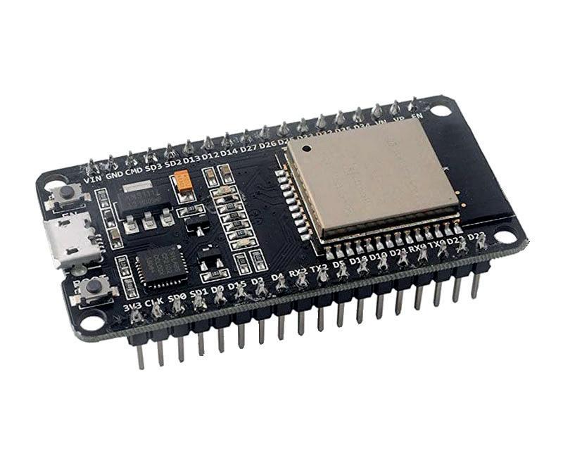
The ESP32 DevKitC is a small ESP32 processor-based board developed manufactured by Espressif. As shown in Figure 2.1, the board is breadboard compatible and has the dimensions 55 mm × 27.9 mm. The one used in this book had the marking ESPRESSIF ESP32WROOM-32D on its metal plate.
The board has two connectors located along each side of the board for GPIO, clock, and power line interfaces. Each connector has 19 pins. As shown in Figure 2.2, the two connectors carry the following signals:

The board has a mini USB connector for connection to a PC. The board also receives its power from the USB port. Standard +5 V from the USB port is converted into +3.3 V on the board. In addition, two buttons are provided on the board named EN and BOOT, with the following functions:
EN: This is the Reset button. Pressing this button resets the board.
BOOT: This is the Download button. The board is normally in operation mode where the button is not pressed. Pressing and holding down this button and at the same time pressing the EN button starts the firmware download mode allowing firmware to be downloaded to the processor through the USB serial port.
The pins on the ESP32 DevKitC board have multiple functions. Figure 2.3 shows the functions of each pin. For example, pin 10 is shared with functions GPIO port 26, DAC channel 2, ADC channel 19, RTC channel 7, and RX01.

Note that GPIO34, GPIO35, GPIO36, GPIO37, GPIO38 and GPIO39 ports are input only and cannot be used as output ports (GPIO37 and GPIO38 are not available on the ESP32 board).

The board operates at a typical power supply of +3.3 V although the absolute maximum is specified as +3.6 V. It is recommended that the current capacity of each pin should not exceed 6 mA, although the absolute maximum current capacity is specified as 12 mA. It is therefore important to use current limiting resistors while driving external loads such as LEDs. Depending upon the configuration, the RF power consumption during reception is around 80 mA, and it can be in excess of 200 mA during a transmission.
Programming of the ESP32 DevKitC requires the board to be connected to a PC through its mini USB port. The communication between the board and the PC takes place using the standard serial communication protocol. ESP32 DevKitC is preloaded with firmware that can be used to test the board. This firmware is activated by default when power is applied to the board. Before communicating with this firmware you have to run a terminal emulation program on your PC, such as the HyperTerm, Putty, X-CTU, and others.
Practical Audio DSP Projects with the ESP32
Practical Audio DSP Projects with the ESP32
The aim of this book is to teach the basic principles of Digital Signal Processing (DSP) and to introduce it from a practical point of view using the bare minimum of mathematics. Only the basic level of discrete-time systems theory is given, sufficient to implement DSP applications in real time. The practical implementations are described in real time using the highly popular ESP32 DevKitC microcontroller development board. With the low cost and extremely popular ESP32 microcontroller, you should be able to design elementary DSP projects with sampling frequencies within the audio range. All programming is done using the popular Arduino IDE in conjunction with the C language compiler.
After laying a solid foundation of DSP theory and pertinent discussions on the main DSP software tools on the market, the book present the following audio-based sound and DSP projects:
> Using an I2S-based digital microphone to capture audio sound
> Using an I2S-based class-D audio amplifier and speaker
> Playing MP3 music stored on an SD card through an I2S-based amplifier and speaker
> Playing MP3 music files stored in ESP32 flash memory through an I2S-based amplifier and speaker
> Mono and stereo Internet radio with I2S-based amplifiers and speakers
> Text-to-speech output with an I2S-based amplifier and speaker
> Using the volume control in I2S-based amplifier and speaker systems
> A speaking event counter with an I2S-based amplifier and speaker
> An adjustable sinewave generator with I2S-based amplifier and speaker
> Using the Pmod I2S2 24-bit fast ADC/DAC module
> Digital low-pass and band-pass real-time FIR filter design with external and internal A/D and D/A conversion
> Digital low-pass and band-pass real-time IIR filter design with external and internal A/D and D/A conversion
> Fast Fourier Transforms (FFT)

Dogan Ibrahim holds a BSc (Hons) degree in Electronic Engineering, an MSc degree in Automatic Control Engineering, and a PhD degree in Digital Signal Processing and microprocessors. Dogan has worked in many organizations and is a Fellow of the Institution of Engineering and Technology (IET) in UK and is a Chartered electrical engineer. Dogan has authored over 100 technical books and over 200 technical articles on electronics, microprocessors, microcontrollers, and related fields. Dogan is a certified Arduino professional and has many years of experience with almost all types of microprocessors and microcontrollers.
Ahmet Ibrahim holds BSc (Hons) and MSc degrees in the fields of computing, software, and networking. Ahmet has held positions in many industries involved in enterprise computing. He enjoys advising, designing, and implementing complex cloud and on-premises computer systems.
