The Book of 555 Timer Projects


Dogan Ibrahim

Over 45 Builds for the Legendary 555 Chip (and the 556, 558)
●
Dogan Ibrahim
● This is an Elektor Publication. Elektor is the media brand of Elektor International Media B.V. PO Box 11, NL-6114-ZG Susteren, The Netherlands Phone: +31 46 4389444
● All rights reserved. No part of this book may be reproduced in any material form, including photocopying, or storing in any medium by electronic means and whether or not transiently or incidentally to some other use of this publication, without the written permission of the copyright holder except in accordance with the provisions of the Copyright Designs and Patents Act 1988 or under the terms of a licence issued by the Copyright Licencing Agency Ltd., 90 Tottenham Court Road, London, England W1P 9HE. Applications for the copyright holder's permission to reproduce any part of the publication should be addressed to the publishers.
● Declaration
The authors and publisher have used their best efforts in ensuring the correctness of the information contained in this book. They do not assume, and hereby disclaim, any liability to any party for any loss or damage caused by errors or omissions in this book, whether such errors or omissions result from negligence, accident or any other cause.
● ISBN 978-3-89576-624-4 Print
ISBN 978-3-89576-625-1 eBook
● © Copyright 2024 Elektor International Media www.elektor.com
Prepress Production: D-Vision, Julian van den Berg
Editor: Jan Buiting, MA
Printers: Ipskamp, Enschede, The Netherlands
Elektor is the world's leading source of essential technical information and electronics products for pro engineers, electronics designers, and the companies seeking to engage them. Each day, our international team develops and delivers high-quality content - via a variety of media channels (including magazines, video, digital media, and social media) in several languages - relating to electronics design and DIY electronics. www.elektormagazine.com
The 555 timer IC, originally introduced by the Signetics Corporation around 1971, is perhaps one of the most popular analog integrated circuits ever produced. Originally called the IC Time Machine, this chip has been used in many timer related and oscillator projects by countless people over decades. The chip provides a very low-cost design of monostable, astable, and bistable circuits using only a few external passive components such as resistors and a capacitor. Additional terminals are provided for external triggering or resetting the chip.
Since it became commercially available, many novel and unique commercial, industrial, and domestic circuits have been developed using this chip. The 555 timer chip was originally designed using the bipolar junction transistor technology. It is interesting to note that after about 50 years, the 555 chip is still very popular and used in many applications, although the CMOS versions seem to be more popular in portable low-power applications.
Over the years, derivations of the basic 555 timer chip has been produced. The 556 incorporates two timer circuits, while the 558 provides four of these in one package. In 2017, it was reported that over a billion 555 timer chips were produced annually. As a result of this, it is known as the most popular IC ever produced. The chip has been manufactured by many popular chip manufacturers, such as Intel, Texas Instruments, Signetics, Raytheon, STMicroelectronics, and others.
It was initially thought that the part name “555” came from the fact that there are three 5 kΩ resistors used inside the chip. It was however stated by the original manufacturers that the part number 555 was arbitrary and the fact that the chip had three 5 kΩ internal resistors was a coincidence.
This book is about the design of 555 timer IC based projects. Over 45 fully tested and documented projects are given in the book. All the projects given in the book have been tested fully by the author by constructing them individually on a small breadboard. Readers are not required to have any programming experiences for constructing or using the projects given in the book. However, it will be useful if some knowledge is available of basic electronics and the use of a breadboard for constructing and testing electronic circuits. The following subheadings are given for each project in the book:
• Title of the project
• Block diagram
• Design
• Circuit diagram
• Fritzing diagram (where possible)
• Construction details
• Testing procedure
The projects given in the book can be modified or expanded by the readers for their own applications. Electronic engineering students should find the projects useful, especially during the development of their final year projects and in their laboratory work. Additionally, people engaged in designing small electronic circuits and electronic hobbyists should find the projects fun, educational, interesting, and useful.
The author hopes that the readers find the projects in the book motivating and beneficial and hopes that they use a 555 timer IC in their future projects.
Dr Dogan Ibrahim London, 2024
1.1 Overview
The 555 timer IC, originally introduced by the Signetics Corporation around 1971, is sure to rank high among the most popular analog integrated circuits ever produced. Originally called the IC Time Machine, this chip has been used in many timer-related projects by countless people over decades. The chip provides a very low-cost design of monostable, astable, and bistable circuits using only a few external passive components such as resistors and a capacitor. Additional terminals are provided for triggering or resetting. Since it became commercially available, many novel and unique commercial, industrial, and domestic circuits have been developed using this chip. It is interesting to note that after about 50 years, the 555 chip is still very popular and used in lots of applications, although the CMOS versions seem to be more popular in portable low-power applications.
1.2 Types of 555 timer chips
As shown in Table 1.1, the 555 chip is available from many manufacturers under different type codes with prefixed letters, usually to identify the manufacturer. Although all of these chips seem to have different names, their operation is identical, while the packaging and some electrical and thermal specifications may differ slightly.
Manufacturer
Fairchild
Harris
Semiconductor
Intersil
National
RCA
Texas Instruments
Texas Instruments
Motorola
STMicroelectronics
NE555
ICM7555IPA
NE555 / SE555
LM555C / LM1455
CA555CE
NE555P / NE555Y / SA555 / SE555 / SE555C
LMC555
MC1455 / MC1555
TS555
Bipolar
CMOS
Bipolar
Bipolar / CMOS
Bipolar
Bipolar
CMOS
Bipolar / military
CMOS
Table 1.1: Type 555 chips from different manufacturers.
1.3 555 timer chip specifications
This book covers the popular NE555P bipolar chip, whose specifications are given in this section for reference.
1.3.1 The NE555P chip
Please refer to the following Internet website for further information:
https://www.ti.com/product/NE555/part-details/NE555P
Features
• Timing from microseconds to hours
• Astable, monostable, or bistable operation
• Adjustable duty cycle
• Output can sink or source large currents
• Excellent temperature stability
• 8-pin package
Specifications
The basic specifications of the NE555P timer chip are:
• Operating voltage: 4.5 V to 16 V
• Output TTL compatible with 5 V supply voltage
• Supply current: typical 3 mA at 5V
• Output can sink or source 200 mA at 15 V supply
• Monostable accuracy: 1%
• Monostable drift with temperature: 50 ppm/ºC
• Astable accuracy: 2.25%
• Astable drift with temperature: 150 ppm/ºC
• Reset voltage: 1 V maximum
• Trigger voltage: 1.67 V typical at 5 V supply voltage
• Output low voltage: 200 mV maximum at 4.5 V supply, 180 mV at 15 V supply voltage
• Output high voltage: [supply voltage – 2.5 V] at 200 mA sink current and 15 V supply voltage; [supply voltage – 0.25 V] at 5 mA sink current and 5 V supply voltage.
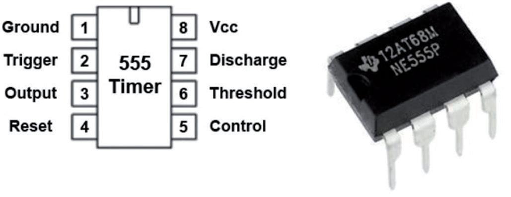
The 555 chip usually comes in an 8-pin plastic DIP (Dual-In-Line Package). Depending on the manufacturer, it consists of 23 transistors, 2 diodes, and 16 resistors. A 14-pin dual version of the chip aptly named “556” is also available that combines two 555s on a single chip. Figure 1.1 shows the internal structure of the 555 chip. The pinout is shown in Figure 1.2.
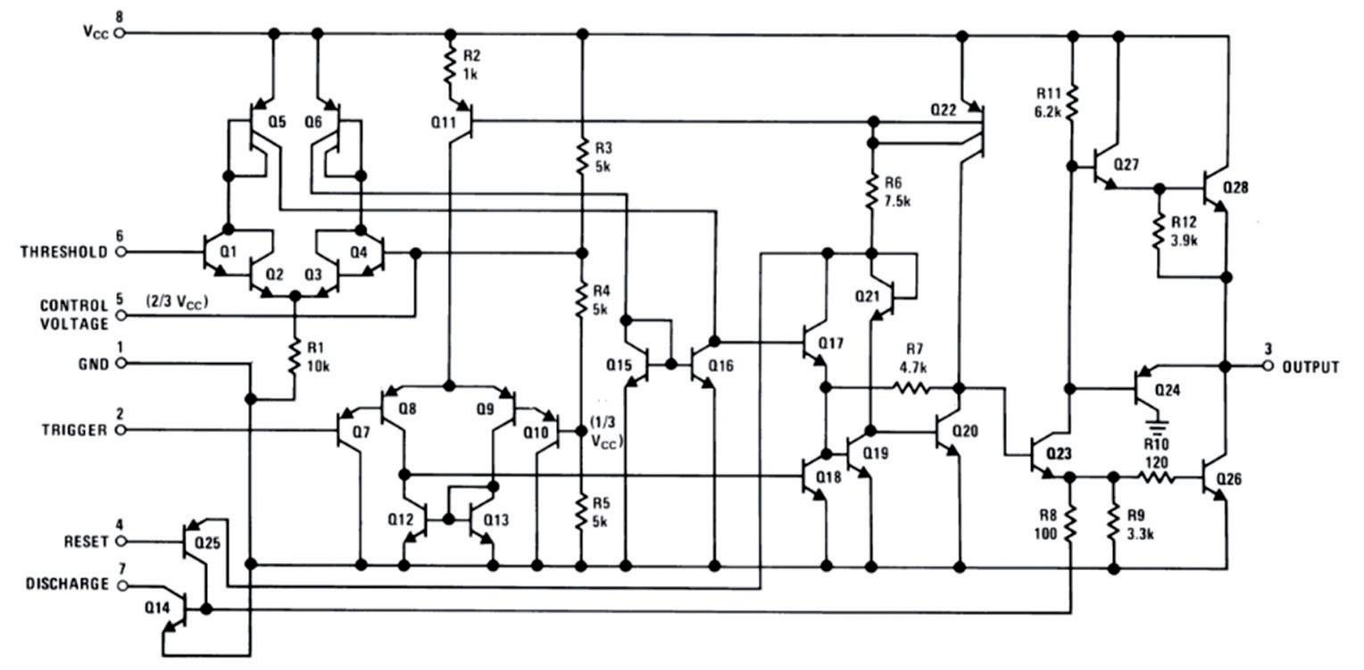
2.1
In order to understand the operation of the 555 timer chip, it is necessary to analyze its block diagram as shown in Figure 2.1.
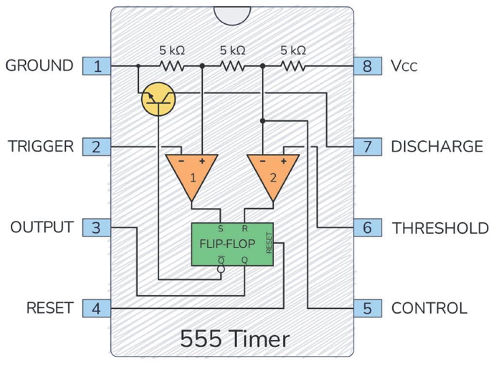
Figure 2.1: 555 timer chip internal block diagram. Source: build-electronic-circuits.com
The block diagram consists of two comparator circuits, an SR flip flop, a transistor, and three resistors.
An astable circuit outputs squarewave signals at the frequency set by external two resistors and a capacitor. Perhaps the easiest way to understand the operation of an astable circuit is to insert the external components into Figure 2.1 and then analyze the circuit.
Figure 2.2 shows an astable circuit. Because of the three identical resistors, the voltage at the positive input of comparator 1 is at 1/3 Vcc, and the voltage at the negative input of comparator 2 is at 2/3 Vcc. When power is applied to the circuit, the capacitor is discharged and because the output of comparator 1 is positive, the flip-flop sets and its Q output (pin 3) goes High. The capacitor charges through resistors R1+R2 and the voltage across it increases. When it reaches 2/3 Vcc, the output of comparator 2 goes positive and resets the flip-flop. As a result, the output voltage at Q goes Low. This turns On the transistor and the capacitor discharges through R2. As soon as the voltage across the capacitor falls to 1/3 Vcc, comparator 1 is triggered. This again causes the flip-flop to set and the output goes High. The transistor cuts off and the cycle repeats with the capacitor charging through R1+R2. As a result, a squarewave voltage is output from the circuit.
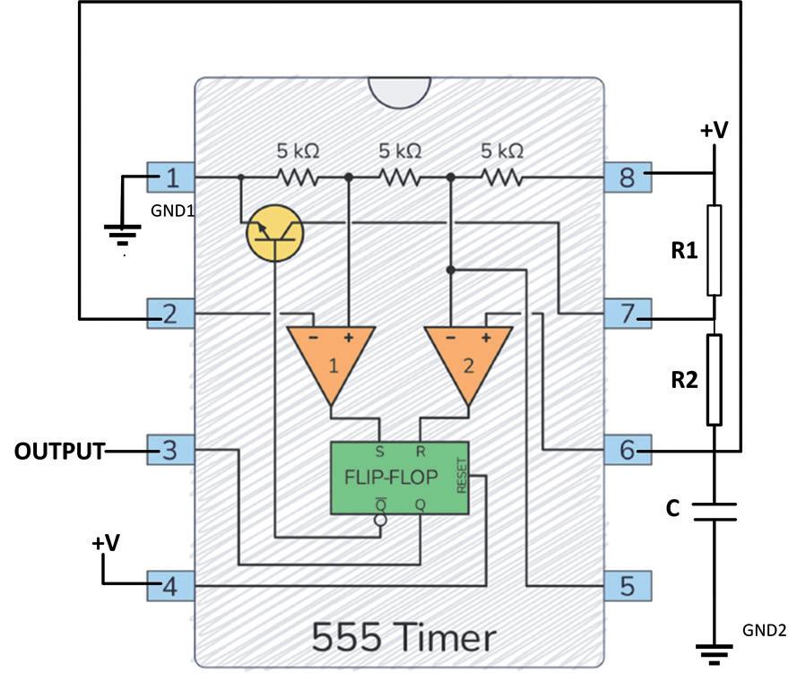
Figure 2.2: Basic astable circuit.
Figure 2.3 shows the output waveforms and the voltage across the capacitor which sets and resets the flip-flop.
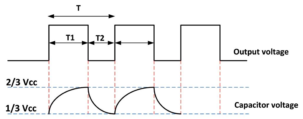
Figure 2.3: Output voltage and voltage across the capacitor.
The period (and hence the frequency) of the output voltage can be calculated as follows. Assuming zero initial conditions, the voltage across a capacitor in an RC circuit rises exponentially, given by the equation:
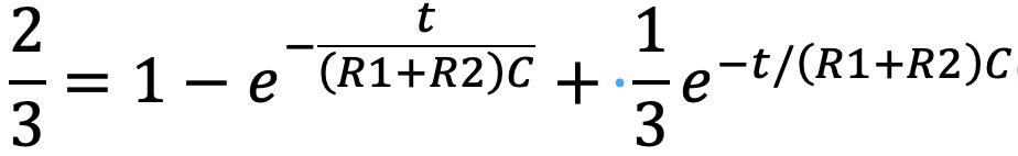
Where Vc is the voltage across the capacitor and Vcc is the applied voltage. CR is known as the time constant of the circuit, and t is the time. However, in our astable circuit the initial voltage across the capacitor is not zero, but it is 1/3 Vcc. The equation describing the voltage across the capacitor with non-zero initial condition is given by:
Where Vo is the initial voltage across the capacitor. In our astable circuit, the voltage rises from 1/3 Vcc to 2/3 Vcc. The equation for the voltage across the capacitor then reduces to:
Chapter 2 ● Operation of the 555 Timer Chip
In this equation, you have to find the time t which is the ON time of the circuit. Simplifying the above equation gives:
Which gives: or,
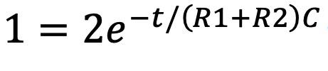
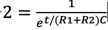
Remembering that ln 2 = 0.693, the On time is then found to be:
tON = 0.693(R1+R2)C
During the OFF time, the capacitor discharges from 2/3 Vcc to 1/3 Vcc through resistor R2. With a similar calculation, we can calculate the OFF time to be:
tOFF = 0.693xR2xC
Therefore, the period of the output waveform is
T = tON + tOFF = 0.693(R1 + 2R2)C
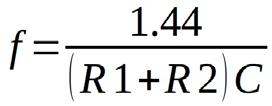
And the frequency is: or,
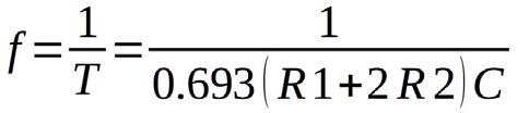
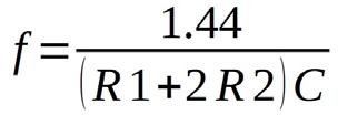
The duty cycle (D) is the ratio of the On time to the period and is given as a percentage by:
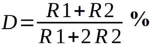
The duty cycle can be adjusted by varying the values of R1 and R2. The 555 timer chip when connected as shown in Figure 2.2 can produce duty-cycles in the range of approximately 55% to 95%. When R1 = R2, the duty cycle is 66%.
In an astable circuit, the values of the components are as follows:
R1 = 10 kΩ, R2 = 4.7 kΩ, and C = 1 μF
Calculate the period, frequency of oscillation, and the duty cycle of this circuit.
Solution 1
tON = 0.693(R1+R2)C = 0.693(10 + 4.7) × 103 × 1 × 10-6 = 10.18 ms
tOFF = 0.693×R2×C = 0.693 × 4.7 × 103 × 1 × 10-6 = 3.25 ms
the period is, T = 10.18 + 3.25 = 13.43 ms
and the frequency of oscillation is, f = 1 / 13.43 ms = 74.4 Hz
the duty cycle is, D = (10 + 4.7) / (10 + 9.4) = 75.77 %
Example 2
You want to design an astable oscillator with a frequency of 1 kHz. Assuming that the capacitor value is 1 μF, calculate suitable resistor values.
Solution 2
You can rewrite the frequency equation as:
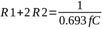
With the given capacitance and frequency values you get: or
Selecting R2 = 270 ohms yields: R1 = 1443 – 2 × 270 = 903 ohms.
The duty cycle is given by: D = (903 + 270) / (903 + 2 × 270) = 81.28 %
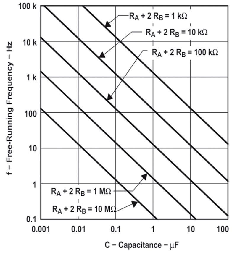
2.2.1 Using a nomogram
A nomogram is available for calculating the approximate component values for a required frequency. Figure 2.4 shows such a nomogram obtained from the Texas Instruments NE555P data sheet. Notice that in this figure, RA and RB correspond to R1 and R2 respectively in Figure 2.2.
2.2.2 555 astable online calculator
Online calculators are available on the internet for calculating the 555 component values. Two types of calculators are available: Standard calculator where the component values are entered and the period, frequency, and duty cycle are calculated. Reverse calculator where the required frequency and some component values are entered and the missing component value is calculated.
Standard calculator
One such calculator is available at the following website: https://ohmslawcalculator.com/555-astable-calculator
you will need to enter the component values with the correct units. The program will display the frequency, period, duty cycle, ON time and OFF time. An example is given below.
Example 3
The component values in an astable circuit are:
C = 1 μF, R1 = 903 ohms and R2 = 270 ohms. Use the online calculator given above to calculate the frequency, etc.
Solution 3
• Start the online calculator
• Enter the component values as shown in Figure 2.5
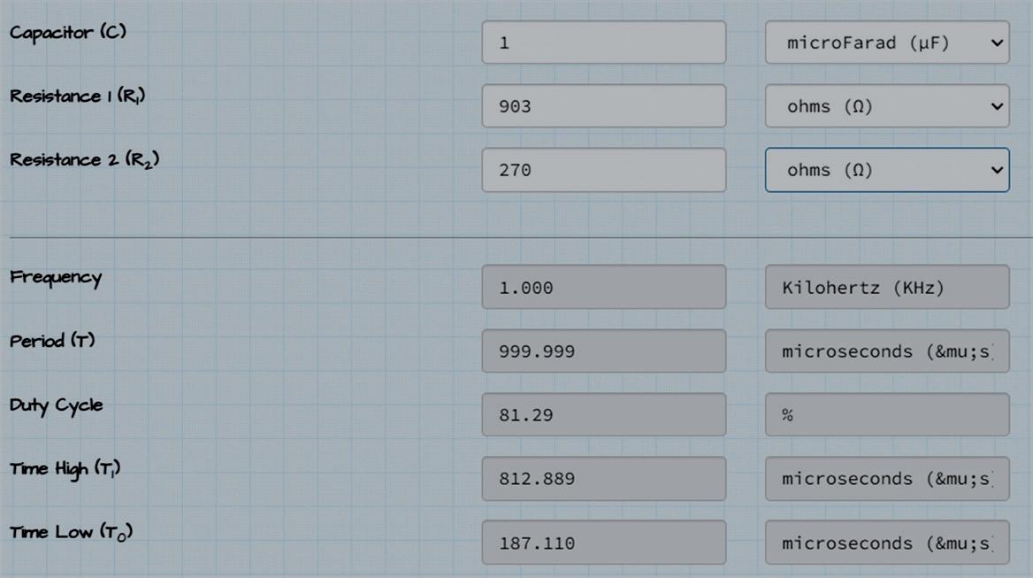
Figure 2.5: Enter the component values.
• The results will be displayed at the bottom part of the display as shown in Figure 2.5.
Reverse calculator
One such calculator is available at the following website: https://www.daycounter.com/Calculators/NE555-Calculator.phtml
An example is given below.
Example 4
You want to design an astable circuit with the following requirements:
F = 1 kHz, C = 1 μF, R1 = 288 ohms, duty cycle = 60 %. Calculate the required value of R2.
Solution 4
• Start the online calculator
• Enter the values of f, C, and R1 (RA in the calculator) as shown in Figure 2.6
• Click Compute. The required value of R2 (RB in the calculator) is given as 576 ohms
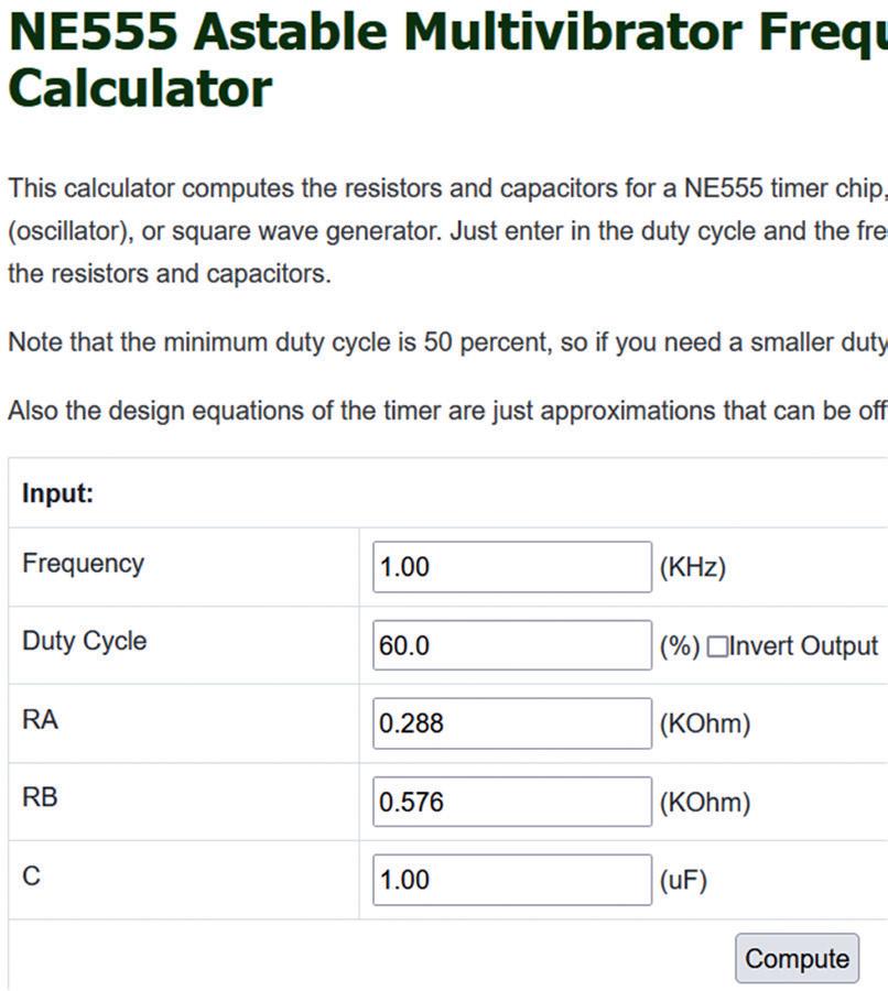
Figure 2.6 Enter the frequency, C and R1 value.
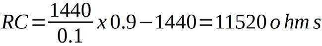
2.2.3 Astable circuit with duty cycle less than or equal to 50% In some applications like fast pulse output generation you may want to have an astable circuit with duty cycle under 50%. This can be achieved with the modified circuit shown in Figure 2.7. Here, two diodes are used. The capacitor now charges through R1 (since R2 is shorted by diode) and discharges through R2. The frequency of oscillation and duty cycle are now given by:
Duty cycle = R1 / (R1 + R2)
For example, for a 50% duty cycle, 0.5 = R1 / (R1 + R2), or, set R1 = R2. Similarly, for 10% duty cycle, set 0.1 = R1 / (R1 + R2), or, set R2 = 0.9R1.
Figure 2.7: Astable with duty cycle under 50%.
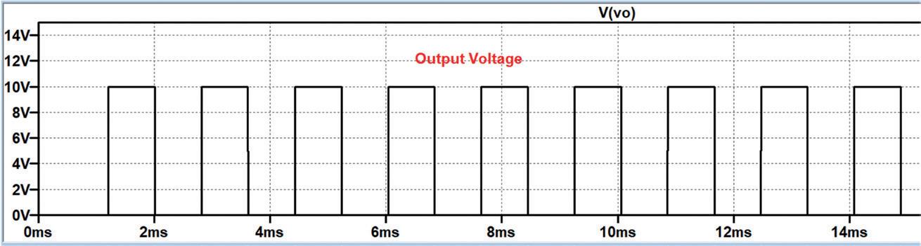
Example 5
Design an astable circuit with 50% duty cycle. Assume that R1 = R2 = 10 kΩ and C = 0.1 μF. Simulate the circuit using the LTspice simulator.
Solution 5
Figure 2.8 shows the LTspice schematic of the required astable circuit. The output voltage waveform of the simulation is shown in Figure 2.9. clearly the duty cycle is 50%.
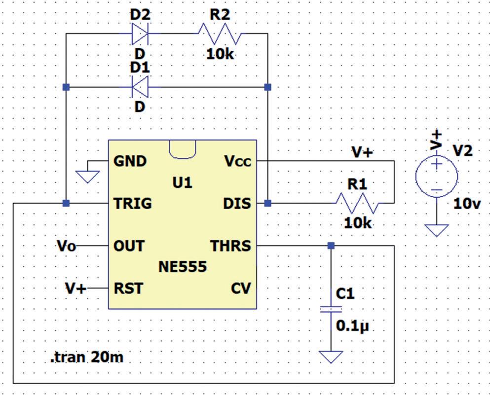
Figure 2.8: LTspice schematic of the astable.
2.2.4 Astable circuit with duty cycle adjustable from 0% to 100%
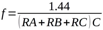
In some applications, you may want to change the duty cycle from 0% to 100%. This can be achieved with the modified circuit shown in Figure 2.10. Here, two diodes and a potentiometer are used. The capacitor now charges through R1 = RA + RX, and discharges through R2 = RB + RC – RX, where RC is the potentiometer. The frequency of oscillation and duty cycle are given by:
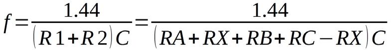
Giving,
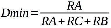
As the potentiometer arm is moved, minimum duty cycle is:
And the maximum duty cycle is:
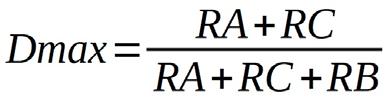
Figure 2.10: Astable with duty cycle variable from 0% to 100%.
2.2.5 Component values for required frequency and duty cycle range
As shown in the previous section, there are three formulas that can be used to design for a required frequency and duty cycle range. Let’s assume that the capacitor value is chosen in advance. These formulas are: f and C are known
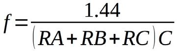
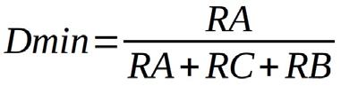
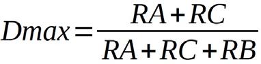
From these equations we can write:
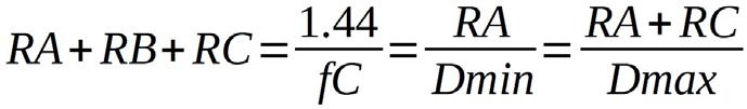
We can then calculate the required component values using the following 3 equations:
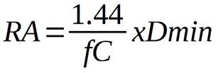
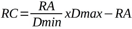
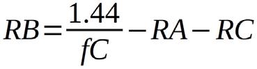
(2.3)
Note: The above calculations do not consider the effects of the diodes in the frequency and duty cycle calculations.
Example 6
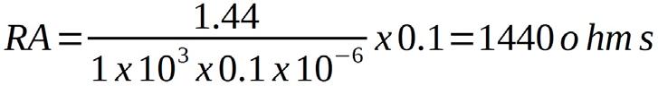
You wish to design an astable circuit with variable duty cycle where the duty cycle is to be changed from 10% to 90% using a potentiometer. The required frequency of oscillation is 1 kHz. Assume that the capacitor is chosen as C = 0.1 μF.
Solution 6
Here, f = 1 kHz, C = 0.1 μF, Dmin = 0.1 and Dmax = 0.9.
From equation (2.1),
From equation (2.2),
From equation (2.3),
Figure 2.11 shows the LTspice schematic of the circuit when the potentiometer arm is at one side. Here, the duty cycle is about 10% as shown in Figure 2.12.
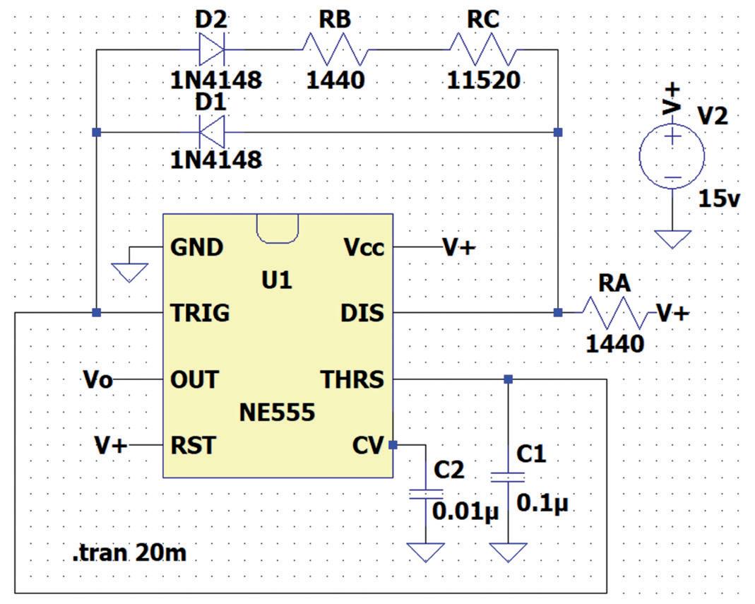
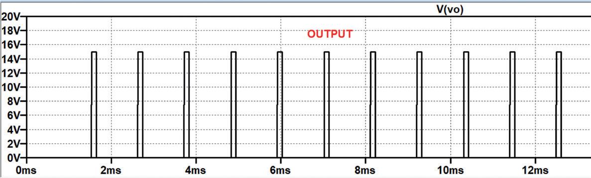
Figure 2.12: Output waveform.
Figure 2.13 shows the LTspice schematic of the circuit when the potentiometer arm is at the ther side. Here, the duty cycle is about 90% as shown in Figure 2.14.
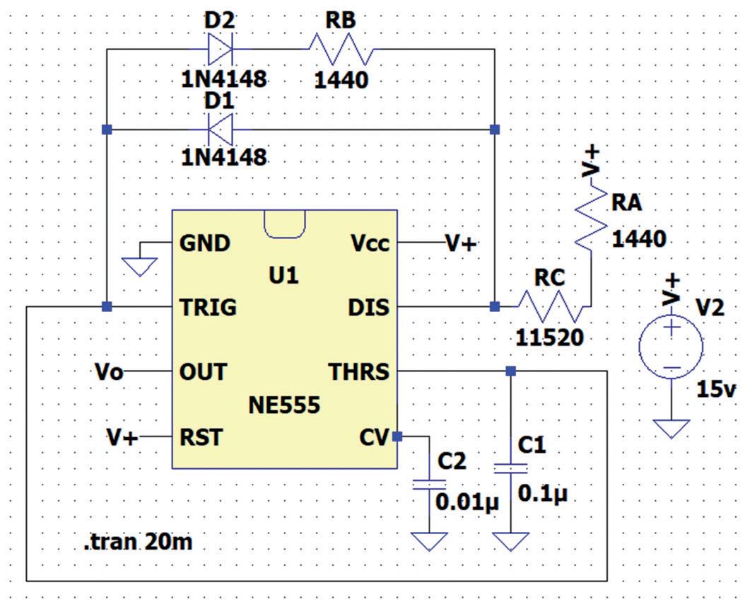
Figure 2.13: LTspice schematic.
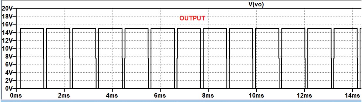
Figure 2.14: Output waveform.
2.2.6 A simpler circuit for 50% duty cycle
Figure 2.15 shows a simpler circuit which yields 50% duty cycle. Here, capacitor C is charging and discharging through the same resistor R. When the output is High, the capacitor charges up through R and when the output is Low, it discharges through R. The equation for the frequency is given by:
Figure 2.15: Simpler astable with 50% duty cycle.
An example is given below.
Example 7
Design an astable circuit with 50% duty cycle, having a frequency of 5 kHz. Assume that C = 0.1 μF.
Solution 7
From the equation, R2 is found to be:
Giving: R = 1442 ohms.
Figure 2.16 shows the LTspice schematic of the circuit. The output waveform is shown in Figure 2.17 where the duty cycle is 50%.
The 555 timer IC, originally introduced by the Signetics Corporation around 1971, is sure to rank high among the most popular analog integrated circuits ever produced. Originally called the IC Time Machine, this chip has been used in many timer-related projects by countless people over decades. This book is all about designing projects based on the 555 timer IC. Over 45 fully tested and documented projects are presented. All projects have been fully tested by the author by constructing them individually on a breadboard. You are not expected to have any programming experiences for constructing or using the projects given in the book. However, it’s definitely useful to have some knowledge of basic electronics and the use of a breadboard for constructing and testing electronic circuits. Some of the projects in the book are:
> Alternately Flashing Two LEDs
> Changing LED Flashing Rate
> Touch Sensor On/O Switch
> Switch On/O Delay
> Light-Dependent Sound
> Dark/Light Switch
> Tone Burst Generator
> Long Duration Timer
> Chasing LEDs
> LED Roulette Game
> Tra ic Lights
> Continuity Tester
> Electronic Lock
> Switch Contact Debouncing
> Toy Electronic Organ
> Multiple Sensor Alarm System
> Metronome
> Voltage Multipliers
> Electronic Dice
> 7-Segment Display Counter
> Motor Control
> 7-Segment Display Dice
> Electronic Siren
> Various Other Projects
The projects given in the book can be modified or expanded by you for your very own applications. Electronic engineering students, people engaged in designing small electronic circuits, and electronic hobbyists should find the projects in the book instructive, fun, interesting, and useful.

Prof Dr Dogan Ibrahim has a BSc degree in electronic engineering, an MSc degree in automatic control engineering, and a PhD degree in digital signal processing. Dogan has worked in many industrial organizations before he returned to academic life. Prof Ibrahim is the author of over 70 technical books and published over 200 technical articles on microcontrollers, microprocessors, and related fields. He is a Chartered electrical engineer and a Fellow of the Institution of the Engineering Technology. He is a certified Arduino professional.
Elektor International Media www.elektor.com