
Mastering the Arduino Uno R4
Programming and Projects for the Minima and WiFi
 Dogan Ibrahim
Mastering the Arduino Uno R4
Programming and Projects for the Minima and WiFi
● Dogan Ibrahim● This is an Elektor Publication. Elektor is the media brand of Elektor International Media B.V.
PO Box 11, NL-6114-ZG Susteren, The Netherlands
Phone: +31 46 4389444
● All rights reserved. No part of this book may be reproduced in any material form, including photocopying, or storing in any medium by electronic means and whether or not transiently or incidentally to some other use of this publication, without the written permission of the copyright holder except in accordance with the provisions of the Copyright Designs and Patents Act 1988 or under the terms of a licence issued by the Copyright Licencing Agency Ltd., 90 Tottenham Court Road, London, England W1P 9HE. Applications for the copyright holder's permission to reproduce any part of the publication should be addressed to the publishers.
● Declaration
The author, editor, and publisher have used their best efforts in ensuring the correctness of the information contained in this book. They do not assume, and hereby disclaim, any liability to any party for any loss or damage caused by errors or omissions in this book, whether such errors or omissions result from negligence, accident or any other cause. All the programs given in the book are Copyright of the Author and Elektor International Media. These programs may only be used for educational purposes. Written permission from the Author or Elektor must be obtained before any of these programs can be used for commercial purposes.
● British Library Cataloguing in Publication Data
A catalogue record for this book is available from the British Library
● ISBN 978-3-89576-578-0 Print
ISBN 978-3-89576-579-7 eBook
● © Copyright 2023: Elektor International Media B.V.
Editors: Alina Neacsu; Jan Buiting MA
Prepress Production: D-Vision, Julian van den Berg
Print: Ipskamp Printing, Enschede (NL)
Elektor is the world's leading source of essential technical information and electronics products for pro engineers, electronics designers, and the companies seeking to engage them. Each day, our international team develops and delivers high-quality content - via a variety of media channels (including magazines, video, digital media, and social media) in several languages - relating to electronics design and DIY electronics. www.elektormagazine.com
● 4
Contents ● 5 Contents Preface ........................................................... 11 Chapter 1 ● The Arduino Uno R4 ....................................... 12 1.1 Overview .................................................... 12 1.2 The Arduino Uno R4 against Uno R3 ................................. 13 1.3 The Arduino Uno R4 Minima hardware ................................ 15 1.4 The Arduino Uno R4 Projects Kit .................................... 20 Chapter 2 ● Arduino Uno R4 Program Development ........................ 23 2.1 Overview 23 2.2 Installing the Arduino IDE 2.1.0 .................................... 24 2.3 Software-only programs 26 2.3.1 Example 1: Sum of integer numbers ................................ 26 2.3.2 Example 2: Table of squares 29 2.3.3 Example 3: Volume of a cylinder .................................. 30 2.3.4 Example 4: Centigrade to Fahrenheit 31 2.3.5 Example 5: Times table ......................................... 33 2.3.6 Example 6: Table of trigonometric sine 34 2.3.7 Example 7: Table of trigonometric sine, cosine and tangent ................ 36 2.3.8 Example 8: Integer calculator .................................... 37 2.3.9 Example 9: Dice .............................................. 40 2.3.10 Example 10: Floating point calculator .............................. 41 2.3.11 Example 11: Binary, octal, hexadecimal............................. 43 2.3.12 Example 12: String functions .................................... 44 2.3.13 Example 13: Initializing an array 46 2.3.14 Example 14: Character functions ................................. 48 2.3.15 Example 15: Solution of a quadratic equation 50 2.3.16 Example 16: Lucky day of the week ............................... 53 2.3.17 Example 17: Factorial of a number 54 2.3.18 Example 18: Add two square matrices .............................. 56 Chapter 3 ● Hardware Projects with LEDs ................................ 59 3.1 Overview .................................................... 59
Mastering the Arduino Uno R4 ● 6 3.2 Project 1: Blinking LED – using the on-board LED ........................ 59 3.3 Project 2: Blinking LED – using an external LED ......................... 60 3.4 Project 3: LED flashing SOS ....................................... 63 3.5 Project 4: Alternately blinking LEDs 64 3.6 Project 5: Chaser-LEDs .......................................... 67 3.7 Project 6: Chasing LEDs 2 70 3.8 Project 7: Binary counting LEDs .................................... 72 3.9 Project 8: Random flashing LEDs - Christmas lights 74 3.10 Project 9: Button controlled LED ................................... 75 3.11 Project 10: Controlling the LED flashing rate - external interrupts 80 3.12 Project 11: Reaction timer ....................................... 83 3.13 Project 12: LED color wand 85 3.14 Project 13: RGB fixed colors ...................................... 87 3.15 Project 14: Traffic lights ......................................... 89 3.16 Project 15: Traffic lights with pedestrian crossings ....................... 94 3.17 Project 16: Using the 74HC595 shift register – binary up counter ........... 100 3.18 Project 17: Using the 74HC595 shift register - random flashing 8 LEDs ....... 103 3.19 Project 18: Using the 74HC595 shift register - chasing LEDs ............... 104 3.20 Project 19: Using the 74HC595 shift register - turn ON a specified LED 105 3.21 Project 20: Using the 74HC595 shift register - turn ON specified LEDs ........ 107 Chapter 4 ● 7-Segment LED Displays ................................... 109 4.1 Overview ................................................... 109 4.2 7-Segment LED display structure 109 4.3 Project 1: 7-Segment 1-digit LED counter ............................ 111 4.4 Project 2: 7-Segment 4-digit multiplexed LED display 114 4.5 Project 3: 7-Segment 4-digit multiplexed LED display countertimer interrupts ................................................. 119 4.6 Project 4: 7-Segment 4-digit multiplexed LED display counterblanking leading zeroes 124 4.7 Project 5: 7-Segment 4-digit multiplexed LED display - reaction timer ......... 128 4.8 Project 6: Timer interrupt blinking on-board LED ........................ 133 Chapter 5 ● Liquid Crystal Displays .................................... 136 5.1 Overview ................................................... 136
Contents ● 7 5.2 The I2C bus.................................................. 136 5.3 I2C ports of the development board ................................. 137 5.4 I2C LCD .................................................... 137 5.5 Project 1: Display text on the LCD 140 5.6 Project 2: Scrolling text on the LCD ................................. 142 5.7 Project 3: Display custom characters on the LCD 144 5.8 Project 4: LCD based conveyor belt goods counter....................... 145 5.9 Project 5: LCD based accurate clock using timer interrupts 149 5.10 Project 6: LCD dice ........................................... 154 Chapter 6 ● Sensors ................................................ 157 6.1 Overview ................................................... 157 6.2 Project 1: Analog temperature sensor 157 6.3 Project 2: Voltmeter............................................ 160 6.4 Project 3: On/off temperature controller .............................. 161 6.5 Project 4: Darkness reminder – using a light-dependent resistor (LDR) ........ 164 6.6 Project 5: Tilt detection ......................................... 167 6.7 Water level sensor ............................................. 169 6.7.1 Project 6: Displaying water level .................................. 169 6.7.2 Project 7: Water level controller .................................. 172 6.7.3 Project 8: Water flooding detector with buzzer ........................ 174 6.8 Project 9: Sound detection sensor — control the relay by clapping hands 175 6.9 Project 10: Flame sensor - fire detection with relay output ................. 177 6.10 Project 11: Temperature and humidity display 180 6.11 Project 12: Generating musical tones - melody maker ................... 184 Chapter 7 ● The RFID Reader ......................................... 187 7.1 Overview ................................................... 187 7.2 Project 1: Finding the Tag ID 187 7.3 Project 2: RFID door lock access with relay............................ 190 Chapter 8 ● The 4×4 Keypad ......................................... 194 8.1 Overview ................................................... 194 8.2 Project 1: Display the pressed key code on the Serial Monitor ............... 195 8.3 Project 2: Integer calculator with LCD ............................... 198
Mastering the Arduino Uno R4 ● 8 8.4 Project 3: Keypad door security lock with relay ......................... 203 Chapter 9 ● The Real-Time Clock (RTC) Module ........................... 207 9.1 Overview ................................................... 207 9.2 The supplied RTC module 207 9.3 Project 1: RTC with Serial Monitor .................................. 207 9.4 Project 2: RTC with LCD 211 9.5 Project 3: Temperature and humidity display with time stamping ............ 213 9.6 Using the built-in RTC 216 9.6.1 Project 4: Setting and displaying the current time ..................... 216 9.6.2 Project 5: Periodic interrupt every 2 seconds 218 Chapter 10 ● The Joystick............................................ 221 10.1 Overview 221 10.2 The joystick ................................................ 221 10.3 Project 1 - Reading analog values from the joystick ..................... 221 Chapter 11 ● The 8×8 LED Matrix ...................................... 226 11.1 Overview .................................................. 226 11.2 The supplied 8×8 LED matrix .................................... 226 11.3 Project 1: Displaying shapes ..................................... 227 Chapter 12 ● Motors: Servo and Stepper ................................ 231 12.1 Overview .................................................. 231 12.2 The servo motor 231 12.2.1 Project 1: Test-rotate the servo ................................. 232 12.2.2 Project 2: Servo sweep 234 12.2.3 Project 3: Joystick-controlled servo ............................... 235 12.3 The stepper motor 237 12.3.1 Project 4: Rotate the motor clockwise and then anticlockwise............. 238 Chapter 13 ● The Digital To Analog Converter (DAC) ....................... 241 13.1 Overview .................................................. 241 13.2 Project 1: Generating a square wave with 2 V amplitude 241 13.3 Generating sine wave – using the analogWave library ................... 242 13.3.1 Project 2: Generate a sine wave ................................. 243
Contents ● 9 13.3.2 Project 3: Sine wave sweep frequency generator ..................... 244 13.3.3 Project 4: Generate sine wave whose frequency changes with potentiometer .. 245 13.3.4 Project 5: Generate a square wave with frequency of 1 kHz and amplitude of 1 V ................................................. 247 Chapter 14 ● Using the EEPROM, the Human Interface Device, and PWM ....... 248 14.1 Overview .................................................. 248 14.2 The EEPROM memory 248 14.3 Human Interface Device (HID) ................................... 249 14.4 Project 1: Keyboard control to launch Windows programs 250 14.5 The Pulse Width Modulation (PWM) ................................ 253 14.5.1 PWM channels of the Arduino Uno R4 255 14.5.2 Project 2: LED dimming using PWM ............................... 255 Chapter 15 ● The Arduino Uno R4 WiFi ................................. 257 15.1 Overview .................................................. 257 15.2 The LED matrix .............................................. 260 15.2.1 Project 1: Using LED matrix 1 - creating a large + shape ................ 260 15.2.2 Project 2: Creating images by setting bits .......................... 262 15.2.3 Project 3: Using LED matrix 2 - creating a large + shape ................ 265 15.2.4 Project 4: Animation - displaying a word ........................... 267 15.3 Using the WiFi 269 15.3.1 UDP and TCP .............................................. 269 15.3.2 UDP communication 270 15.3.3 TCP communication .......................................... 271 15.3.4 Project 5: Controlling the Arduino Uno R4 WiFi on-board LED from a smartphone using UDP 272 15.4 Bluetooth .................................................. 276 15.4.1 Bluetooth BLE 277 15.4.2 Bluetooth BLE Software Model .................................. 278 Chapter 16 ● Serial Communications ................................... 280 16.1 Overview .................................................. 280 16.2 Project 1: Receiving ambient temperature from an Arduino Uno R3 .......... 281 Chapter 17 ● Using an Arduino Uno Simulator ............................ 285
Mastering the Arduino Uno R4 ● 10 17.1 Why simulation? ............................................. 285 17.2 The Wokwi simulator .......................................... 286 17.2.1 Project 1: A simple project simulation - flashing LED ................... 287 17.2.2 Project 2: Displaying text on LCD 288 17.2.3 Project 3: LCD seconds counter ................................. 290 Chapter 18 ● The CAN bus ........................................... 292 18.1 Overview .................................................. 292 18.2 The CAN bus 292 18.2.1 CAN bus termination ......................................... 292 18.2.2 CAN bus data rate 294 18.2.3 Cable stub length ........................................... 295 18.2.4 CAN bus node 295 18.2.5 CAN bus signal levels ........................................ 296 18.2.6 CAN_H voltage ............................................. 297 18.2.7 The CAN_L voltage .......................................... 297 18.2.8 Bus arbitration ............................................. 297 18.2.9 Bus transceiver ............................................. 297 18.2.10 CAN connectors ........................................... 298 18.3 Arduino Uno R4 CAN bus interface 300 18.3.1 CAN bus transceivers......................................... 300 18.4 Project 1: Arduino Uno R4 WiFi to Arduino Uno R4 Minima CAN bus communication 301 18.5 Project 2: Sending the temperature readings over the CAN bus ............. 306 Chapter 19 ● Infrared Receiver and Remote Controller ..................... 311 19.1 Overview .................................................. 311 19.2 The supplied infrared receiver 311 19.3 The supplied infrared remote control transmitter unit .................... 311 19.4 Operation of an infrared remote control system 312 19.5 Project 1: Decoding the IR remote control codes ....................... 314 19.6 Project 2: Remote relay activation/deactivation ........................ 317 19.7 Project 3: Infrared remote stepper motor control....................... 320 Index ........................................................... 325
Preface
"Arduino" is an open-source microcontroller development system that incorporates system hardware, an Integrated Development Environment (IDE), and a large number of libraries. Arduino is supported by a large community of programmers, electronic engineers, enthusiasts, and academics. There are several distinctive designs of the basic Arduino board. Although they are intended for diverse types of applications, they can all be programmed using the same IDE, and, in general, programs can be transported ("ported") between different boards. This is probably one of the reasons for the popularity of the Arduino family. Arduino is also supported by a large number of software libraries for many interface devices that can easily be included in your programs. Using these libraries makes programming relatively easy and speeds up the programming time. Using libraries also makes it easier to test your programs since most libraries have already been fully tested and working.
The Arduino Uno R3 board probably ranks as the most popular Arduino family member to date and has been with us for many years. Based on the low-cost 8-bit ATmega328P processor, the Uno R3 has been used by students and hobbyists in many beginning and intermediate-level, low-speed projects requiring small to medium amounts of memory. Perhaps one of the attractive points of the Uno R3 was its powerful IDE and the simplicity of using it to develop projects in relatively short times.
Recently, the new Arduino Uno R4 was announced. This new board is compatible with the earlier Uno R3 but offers highly improved specifications compared to Uno R3. The new Arduino Uno R4 is based on a 48 MHz 32-bit Cortex-M4 processor with a large amount of SRAM and flash memory. Additionally, a higher-precision ADC and a new DAC are added to the design. The contemporary design also supports the CAN bus interface. Two versions of the board are available: Uno R4 Minima, and Uno R4 WiFi.
This book is about using these new boards to develop many different and interesting projects. The projects given in the book have been fully tested with just a handful of parts and external modules, which are available as a kit from Elektor. The block diagrams, circuit diagrams, full program listings, and complete program descriptions are given for all the projects in the book. You should find it easy to build the project hardware and then follow the software descriptions given for the projects. It should also be relatively easy to modify the hardware and software for your own project applications.
I hope that you enjoy reading the book and at the same time learn how to use the Arduino Uno R4 Minima or the R4 WiFi models in your innovative projects.
Dogan Ibrahim London, 2023Publisher's Notice: All programs discussed in this Guide are contained in an archive file you can download free of charge from the Elektor website. Head to www.elektor.com/ books and enter the book title in the Search box.
● 11
Chapter 1 ● The Arduino Uno R4
1.1 Overview
The Arduino project started out as a tool for students at the Interactive Design Institute, Ivrea in Italy back in 2005. The aim of this project was to provide low-cost and easyto-use hardware and software to beginner students and hobbyists to create simple projects using sensors and actuators. The name "Arduino" comes from the bar named Arduin of Ivrea where the project's founders used to meet for drinks. The name of this bar came from the Margrave Arduin of Ivrea, who was King of Italy from 1002 to 1014.
The initial Arduino project team consisted of Massimo Banzi, David Cuartielles, Tom Igoe, Gianluca Martino, and David Mellis. In 2003 Hernando Barragan created the development platform Wiring as a master's thesis at the Institute Ivrea. Wiring was an open-source electronics platform consisting of a programming language, an integrated development environment (IDE), and a single-board microcontroller. This project was developed under the supervision of Massimo Banzi and Casey Reas. The Wiring platform included a printed circuit board with an ATmega128 microcontroller, an IDE, and some library functions. Later in 2005, Massimo Banzi, David Mellis, and David Cuartielles extended the Wiring platform by adding support for the ATmega8 microcontroller which was cheaper. This new project was named Arduino. The project was so successful that after developing less expensive versions, by mid-2011 over 300,000 copies of Arduino were produced commercially and by 2013 this number increased to over 800,000.
Arduino is an open-source hardware where the designs are distributed under a Creative Commons license and are freely available. The only point is that the developers are requested the name Arduino to be reserved for the official product and not be used for similar copy work without permission.
One of the nice features of the Arduino series is that a pre-programmed boot loader is used on the on-board processor. Users can develop their programs using the IDE and then upload their programs to the Arduino processor with the help of this boot loader program. The I/O pins are available at female headers located on either side of the board. This makes the hardware development very easy as jumper wires can be used to make connections to the board.
The original Arduino board was manufactured by the Italian company called Smart Projects. Many versions of the Arduino have been developed over the years by several companies. Some versions are:
• Arduino Diecimila
• Arduino Uno R2
• Arduino Leonardo
• Arduino RS232
• Arduino Pro
• Arduino Mega
• Arduino LilyPad
Mastering the Arduino Uno R4 ● 12
• Arduino Robot
• Arduino Esplora
• Arduino Yun
• Arduino Fio
• Arduino Ethernet
• Arduino Due
• Arduino Nano
• Arduino Uno SMD R3
• Arduino Uno R3
• Arduino MKR Zero
• Arduino Zero
• … and many more
The Arduino family has been so popular that in 2022, its revenue amounted to over US$237 million, including a large portion of online sales via the Internet.
Two new versions of the Arduino have recently been announced: Arduino Uno R4 Minima, and Arduino Uno R4 WiFi. In this book, you will be developing projects using both the Arduino Uno R4 Minima and the Arduino Uno R4 WiFi. The new two boards are similar to the very popular Arduino Uno R3 board but they have been expanded in many ways.
1.2 The Arduino Uno R4 against Uno R3
A comparison of the Uno R3 and Uno R4 is given in Table 1.1. Notice that almost all the projects and libraries used with the Uno R3 can be used with the Uno R4 without any modifications. It is recommended however to upgrade any libraries which may have been modified specifically for the Uno R4.
Chapter 1 ● The Arduino Uno R4 ● 13
Feature Arduino Uno R3 Arduino Uno R4 Processor ATmega328P Renesas RA4M1 Word length 8 32 Clock speed 16 MHz 48 MHz SRAM 2 KB 32 KB Flash memory 32 KB 256 KB EEPROM 1 KB 8 KB Operating voltage 5 V 5 V Timers 3 10 Capacitive touch sensing None 27 channels Temperature sensor None 1 USB connector Type B USB-C ADC 10-bit 14-bit DAC None 12-bit SPI 1 1
Mastering the Arduino Uno R4
The Arduino Uno R4 features the Renesas RA4M1 processor, which is an Arm 32-bit Cortex-M4 processor, running at 48 MHz. The Uno R3 had an ATmega328P processor with only a 16 MHz clock. This is a 3 times increase of the clock speed over the Uno R3. Additionally, Uno R4 has 32 KB SRAM memory compared to 2 KB on the Uno R3. The flash memory of the R4 is 256 KB, compared to only 32 KB on the Uno R3. As a result, more complex projects requiring more memory can be developed with the Uno R4. The USB port on the Uno R3 has been replaced with the currently standard USB-C and the maximum power supply voltage has been increased to 24 V with improved thermal design. The processor operating voltage is still 5 V. Arduino Uno R4 provides a CAN bus interface, allowing devices to be connected and programmed on a CAN bus environment. The ADC converter capacity has been increased from 12 bits to 14 bits on the Uno R4. SPI and I2C bus interfaces have been increased from 1 to 2. The Uno R4 supports Human Interface Device (HID) which enables users to simulate a mouse or keyboard when connected to a computer via a USB cable. Users can send mouse movements or keystrokes to a computer. Additionally, Uno R4 includes a true 12-bit DAC converter. The analogWave library was added to make using the DAC easy. Generating a sine, saw or square wave is as easy as calling a library function. Of course, you can do much more with it. The Uno R4 PCB is hardware compatible with the Uno R3. The pinout, voltage, and form factor are unchanged so that the Uno R4 can easily replace designs that use the Uno R3. The software IDE is also compatible between the Uno R3 and Uno R4, where an effort was made to maximize backward compatibility of the Arduino libraries so that users can use the existing libraries without any modifications. Some libraries which depend heavily on the AVR architecture may need to be re-loaded into the IDE. A public list of such libraries will be provided by Arduino.
● 14 I2C 1 2 Qwiic I2C None 1 (WiFi version only) Operating voltage 5 V 5 V Wi-Fi None WiFi version only RTC None 1 (WiFi version only) Human Interface Device None Yes SWD debug None 1 Bluetooth BLE None WiFi version only CAN bus support None 1 Op Amp None 1 128x8 LED matrix None WiFi version only Input voltage 7–12 V 6–24 V Analog inputs 6 6 PWM pins 6 6 USB USB-B USB-C
Table 1.1: Comparison of the Arduino Uno R3 and Uno R4.
Compared to other Cortex-based boards such as the Raspberry Pi Pico, which uses the Cortex M0+, the Cortex-M4 performance is about 6 times better (just to remind you, the Raspberry Pi Pico clock runs at 125 MHz by default). As a result, the Arduino Uno R4 can be used in highly complex real-time projects (e.g. digital control, DSP, AI, etc.) requiring large memory and fast throughput.
As mentioned earlier, Arduino Uno R4 is available in two versions: WiFi and Minima. The WiFi version is equipped with an Espressif S3 Wi-Fi module, making the board ideal in IoTbased network and Bluetooth BLE applications, as well as in applications requiring Internet connectivity. Additionally, a 128×8 LED matrix is included on the board. The Minima version offers a cost-effective option with no WiFi or Bluetooth connectivity. In this book, all the projects compile and run on both versions, except that the WiFi and LED Matrix projects only compile and run on the R4 WiFi version.
In summary, the Uno R4 is a giant leap forward for Arduino as it is a truly remarkable board that will take your microcontroller project experience to the next level. Perhaps one disadvantage of the Uno R4 compared to Uno R3 is its increased price.
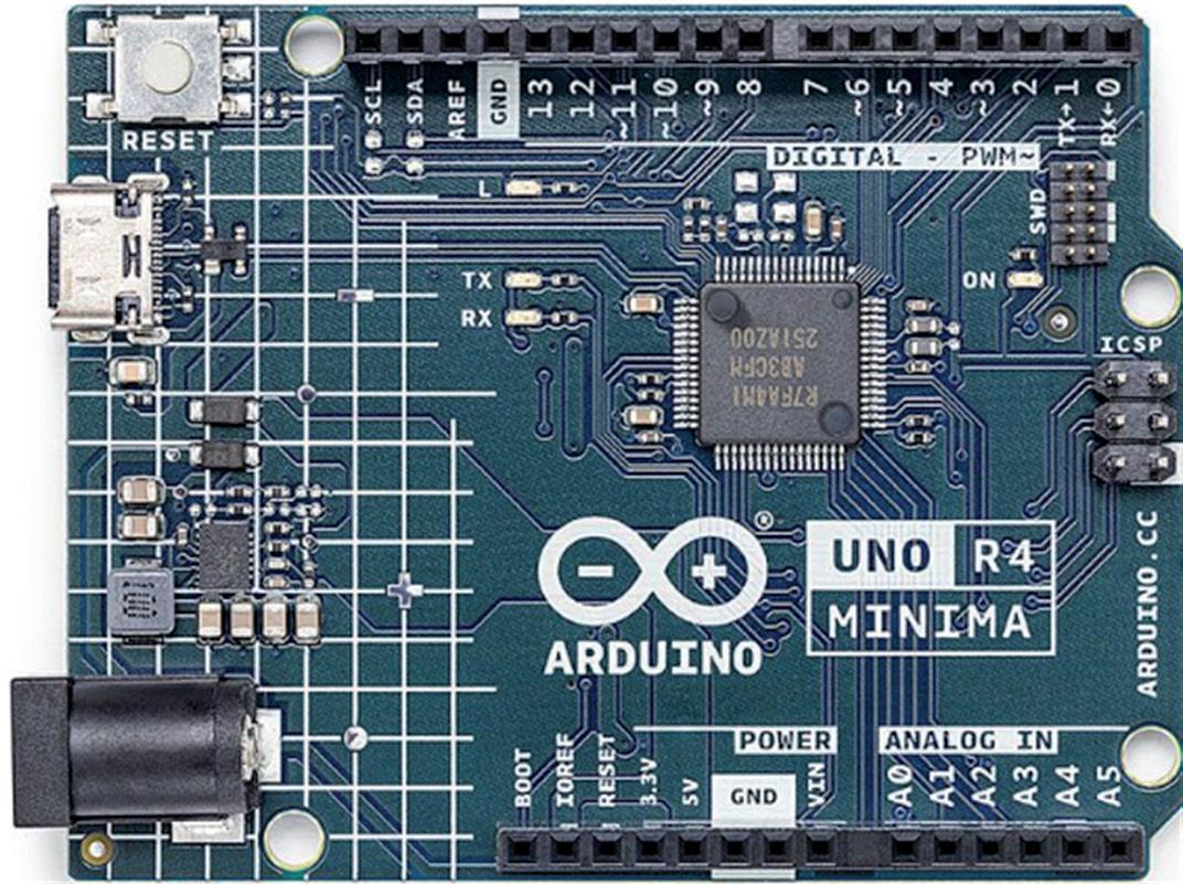
1.3 The Arduino Uno R4 Minima hardware
Figure 1.1 shows the Arduino Uno R4 PCB layout. The PCB footpath and the placement of the headers on the PCB are the same as the Uno R3. In the center of the PCB is the RA4M1 microcontroller. On the left-hand side of the PCB, you can see the Reset button, USB-C connector for connecting to a PC, and the barrel connector for supplying external power. At the rear of the PCB, you can see the 6-pin ICSP pins (SPI) and the 10-pin SWD/JTAG pins. An on-board LED is connected to port 13 as in Uno R3. Additionally, yellow LEDs are connected to the serial TX and RX pins to indicate serial data transmission, a green LED indicates power to the board, and a yellow LED indicates the state of the SCK pin.
Chapter 1 ● The Arduino Uno R4 ● 15
Figure 1.1: Arduino Uno R4 Minima PCB layout.
Mastering the Arduino Uno R4
On the two sides of the PCB, you have the header connectors as in the Uno R3. The headers have the following pins (see Figure 1.2):

Short header connector:
• 6× 14-bit analog input pins (A0–A5)
• 1× 12-bit DAC (A0)
• 1× Opamp+ (A1), Opamp– (A2), Opamp Out (A3)
• I2C SDA (A4), I2C SCL (A5)
• Vin
• GND
• +5 V
• +3.3 V output (output from the RA4M1 VCC_USB pin)
• RESET
• IOREF (reference for the digital logic V. Connected to + 5 V)
• BOOT (mode selection)
Note: Analog pins A0–A5 can also be used as digital pins.
Long header connector:
• 14 × digital pins (D0–D13)
• External interrupt (IRQ00: D2, IRQ01: D3)
• 6 × PWM pins (D3, D5, D6, D9, D10, D11)
• UART (RX:D0, TX:D1)
• SPI (same as on ICSP header. D13: SCK, MISO (CIPO): D12, MOSI (COPI): D11, CS: D10)
• CAN (RX:D5, TX: D4 on Minima, RXD13, TX:D10 on WiFi, Note: external transceiver required)
• GND
• AREF (analog reference voltage, connected to +5 V through a 5.1-kΩ resistor)
• I2C SDA (pullups not mounted)
• I2C SCL (pullups not mounted)
ICSP connector:
• See Table 1.2
SWD/JTAG connector:
• See Table 1.3
●
16
Table 1.2: ICSP connector pins (source: Product Reference Manual, SKU: ABX00080).
The recommended operating conditions are shown in Table 1.4. Schottky diodes are used for overvoltage and reverse polarity protection. Power can either be supplied via the VIN pin, the barrel jack (DC jack), or via USB-C connector. If power is supplied via VIN, a


Chapter 1 ● The Arduino Uno R4 ● 17
Table 1.3: SWD/JTAG connector pins (source: Product Reference Manual, SKU: ABX00080).
Figure 1.2: Header pins (source: Product Reference Manual, SKU: ABX00080).
buck converter steps the voltage down to 5 V. Power via USB supplies about 4.7 V (due to Schottky barrier forward bias) to the RA4M1 microcontroller. The RA4M1 processor can operate from +1.6 to +5.5 V and is connected to +5 V on the Arduino board. The digital GPIOs on the RA4M1 microcontroller can handle currents of IOH = 4 mA and IOL = 8 mA (assuming middle pin drive) current. Remember that IOL is the current into the pin (sinking) when the pin is at logic 0, and IOH is the current from the pin (sourcing) when the pin is at logic 1. Care must be taken not to exceed the recommended current drives of the GPIO ports. Figure 1.3 shows a simplified power supply connection of the Arduino Uno R4.
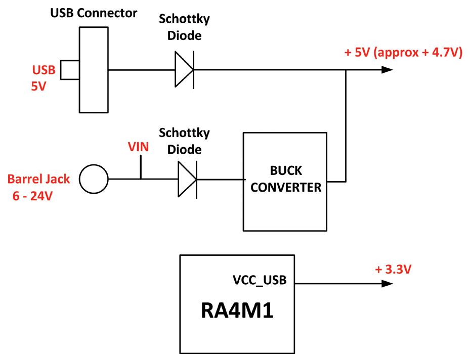
Table 1.4: Recommended operating conditions (source: Product Reference Manual, SKU: ABX00080).

Figure 1.3: Simplified power supply connections.
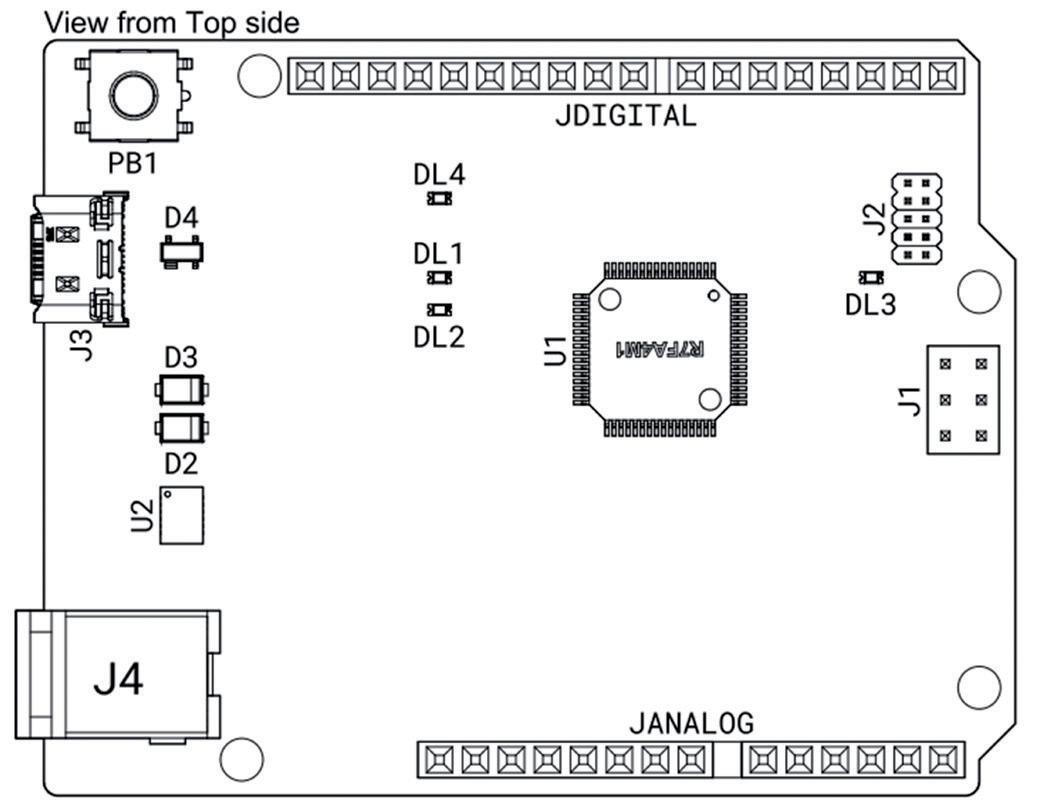
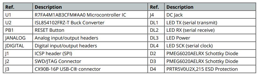
Figure 1.4 shows the pin layout of the Arduino Uno R4 Minima board. The component layout is shown in Figure 1.5 (taken from Product Reference Manual: SKU: ABX00080) with the component descriptions shown in Table 1.5.
Mastering the Arduino Uno R4 ●
18
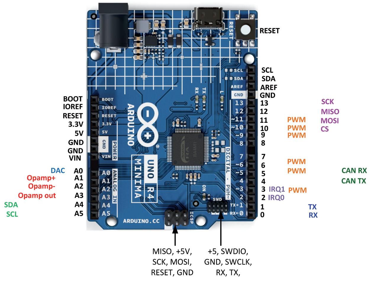
Chapter 1 ● The Arduino Uno R4 ● 19
Figure 1.4: Arduino Uno R4 Minima pin layout.
Figure 1.5: Arduino Uno R4 Minima component layout.
Mastering the Arduino Uno R4
1.4 The Arduino Uno R4 Projects Kit
The Arduino Uno Experimenting (SKU 20339) Kit available from Elektor (www.elektor.com) includes a large number of sensors, actuators, buttons, LEDs, plus a breadboard, stepper motor, jumper wires etc. In detail, the kit includes the following components:
• 1× RFID reader module
• 1× DS1302 clock module
• 1× 5 V stepper motor
• 1× Stepper motor 2003 drive board
• 5x Green Led
• 5× Yellow LED
• 5× Red LED
• 2× Rocker switch
• 1× Flame sensor
• 1× LM35 sensor module
• 1× Infrared receiver
• 3× Light-dependent resistor
• 1× Remote controller
• 1× Breadboard
• 4× Pushbutton (with four caps)
• 1× Buzzer
• 1× Piezo sounder
• 1× Adjustable resistor
• 1× 74HC595 shift register
• 1× 7-segment display
• 1× 4-digit 7-segment display
• 1× 8×8 Dot-matrix display
• 1× 1602 / I2C LCD module
• 1× DHT11 Temperature and humidity module
• 1× Relay module
• 1× Sound module
• Set of Dupont cables
• Set of Breadboard cables
• 1× Water sensor
• 1× USB cable
● 20
Table 1.5: Arduino Uno R4 Minima component layout.
• 1× PS2 Joystick
• 5× 1 kΩ resistor
• 5× 10 kΩ resistor
• 5× 220Ω resistor
• 1× 4×4 keypad module
• 1× SG90 Servo
• 1× RFID card
• 1× RGB module
• 2× jumper cap
• 1× 9 V Battery DC clip-on cable
The kit is supplied in a plastic box with a lid as shown in Figure 1.6 (note: the actual packaging and contents of the kit as received may differ from the photo).

Chapter 1 ● The Arduino Uno R4 ● 21
Figure 1.6: The kit supplied in a plastic box.
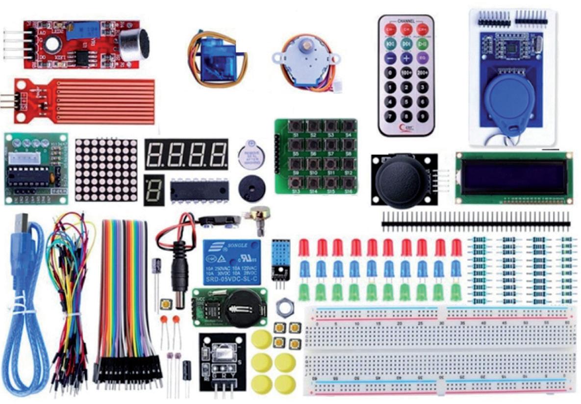
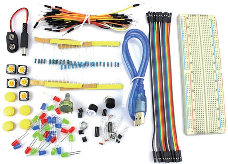
Figure 1.7 shows the supplied components and the Arduino Uno R4, which is not included and must be purchased separately. A close-up picture of the included sensors, actuators, and displays is shown in Figure 1.8. Figure 1.9 shows a close-up picture of the supplied LEDs, resistors, buttons, buzzers, breadboard and wire jumpers.

Mastering the Arduino Uno R4 ● 22
Figure 1.7: Supplied components.
Figure 1.8: Close-up picture of sensors, actuators, and displays.
Figure 1.9: Close-up picture of the LEDs, resistors, buttons, wires, etc.
Chapter 2 ● Arduino Uno R4 Program Development
2.1 Overview
The Arduino code is written in the C++ language, which is currently one of the most popular languages used to program microcontrollers. Arduino can be programmed using either the Desktop Arduino IDE or the Arduino Web Editor. The IDE requires the software to be installed on your PC. This is an Integrated Development Environment (IDE) that consists of an editor, compiler, debugger, and tools to upload the compiled code to the processor on the development board. An Arduino program is called a sketch, which is compiled into machine code and uploaded to the target processor. Arduino Web Editor enables the programmer to develop, compile, and upload programs using an online browser with the advantage that the online tool is always up-to-date and includes the latest libraries and features. In this book, you will be using the IDE. Interested readers can search for Arduino Web Editor in Google and create an account to sign in and use it.
The Arduino IDE has been developed over a decade and there are several versions of it. The latest stable version is 2.1 released in March 2022. Version 1.8.19 has been popular for many years and is still used by many programmers. New version 2.1.0 is the recommended version since it is faster and easier to use than version 1.8.19. The author has used version 2.1.0 in all the projects in this book. Readers may prefer to use the same version in their projects.
In this chapter, you will learn how to install version 2.1.0 of the IDE, which was the latest version at the time of authoring this book. Simple software-only programs are given in this chapter to review the principles of programming using the Arduino IDE. In the next chapters, you will be using the newly released Arduino Uno R4 Minima/WiFi development boards together with the supplied components of the bundle in many real-time project applications.
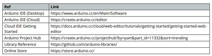
Further information on Arduino IDE, Web Editor, and related tools can be obtained from the links given in Table 2.1.
Chapter 2 ● Arduino Uno R4 Program Development ● 23
Table 2.1: Links to Arduino IDE, Web Editor, and related tools (Product Reference Manual, SKU: ABX00080).
Mastering the Arduino Uno R4
2.2 Installing the Arduino IDE 2.1.0
The latest version of the Arduino IDE can be installed from the following website:

https://www.arduino.cc/en/software
Select your processor from the DOWNLOAD OPTIONS at the right (Figure 2.1). Click JUST DOWNLOAD (unless you want to support by contributing). The author installed it on a Windows 10 laptop and at the time of drafting this book the latest version file name was: Arduino-ide_2.1.0-Windows_64bit.exe.
You now have to install the Board Package for your Arduino Uno R4 Minima. The steps are:
• Start the Arduino IDE.

• Click to Open the Boards Manager at the top left of the screen (Figure 2.2).
●
• Search for ARDUINO UNO R4 (Figure 2.3) and click INSTALL to install it. At the time of drafting this book, the version was: 1.0.1.
24
Figure 2.1: Select your processor to install.
Figure 2.2: Open the Boards manager.
• Click Boards Manager to close the left window.
• You should be able to select the Arduino Uno R4 board from the board selector at the top left of the screen (Figure 2.4). Connect your Arduino Uno R4 Minima (or WiFi) to your PC via a USB-C cable.

• Click Tools Port and select the serial port connected to your Uno R4.

You are now ready to develop programs and upload them to your Arduino Uno R4 Minima/ WiFi processor on your development board.
Before looking at some example programs, it is worthwhile to learn some of the commonly used menu options offered by the IDE.
File: with this menu option you can open existing programs, save programs, open example programs, and set the IDE working environment (e.g., Preferences…).
Edit: with this menu option you can cut, paste, select, go to a specified line, change indentation and font size, and find text in a file.
Sketch: with this menu option you can compile your program, upload the compiled program to the target processor, include libraries, add files and some other options that you will not be using.
Chapter 2 ● Arduino Uno R4 Program Development ● 25
Figure 2.3: Click INSTALL to install the Uno R4 boards.
Figure 2.4: Select: Arduino Uno R4 Minima.
Tools: with this menu option you can manage libraries, configure the serial monitor and serial plotter, select and configure the development board that you will be using, and burn a new bootloader.
Help: this menu option displays various help items on selected topics. Additionally, it displays the version number of the currently used IDE (Figure 2.5). e.g., Version: 2.1.0
2.3 Software-only programs
In this chapter, simple software-only programs are given to review the basic principles of programming in C language using the Arduino IDE. The human interface (e.g. display and keyboard) to these programs is the Serial Monitor of the IDE. The aim here has been to review the C language programming concepts by developing simple programs, and then uploading and running them on your development board. Readers who have a good working knowledge of the C language and who are familiar with the Serial Monitor can skip this chapter.

2.3.1 Example 1: Sum of integer numbers
Write a program to read an integer number N from the keyboard and then calculate and display the sum of all the integer numbers from 1 to N.
Solution 1
Figure 2.6 shows the program listing (Program: sumN). Comments are used at the beginning of the program to describe the function of the program. Also, the names of the author and the program and the date of development of the program are all listed here. It is strongly recommended by the author to include comments in your programs to make them easy to follow and also easy to modify in the future.
The setup() function is executed only once at the beginning of the program. Inside this function, the Serial Monitor is configured to run at 9600 baud (you may choose a different baud rate if you wish).
The main program runs inside the function loop(). Here, variables i, N, and Sum are declared as integers and Sum is cleared to 0. The program prompts the user to enter N which is read using the built-in function parseInt(). The program checks if data is available before reading from the keyboard. Then, a for loop is formed where the sum of all the integer numbers from 1 to N are calculated and stored in variable Sum. The sum is finally
26
Mastering the Arduino Uno R4 ●
Figure 2.5: Displaying the IDE version number.
displayed as an integer using a println() function. Notice that the println() function prints a carriage return and line feed after displaying the data. The program is stopped by using a while() statement at the end, otherwise the loop() function will repeat forever.
The steps to test the program are as follows:
• Connect your Arduino Uno R4 development board to the PC and configure the serial link.
• Type your program as in Figure 2.6 (or load from the Elektor website of the book) and then save it with a suitable name, e.g., sumN.
• Click Sketch Verify/Compile to compile the program. The status of the compilation will be displayed in the bottom panel as Compiling sketch…. If there are any errors, you should go back to your program to correct the errors. If there are no errors, then the bottom panel will display as shown in Figure 2.7 (Click Output at the bottom panel to see this message).
• Click Sketch Upload to upload the correctly compiled code to the processor on your development board. You should see the message Done uploading at the bottom part of the screen.
• Make sure the Baud rate is set to 9600. Click Serial Monitor at the top of the bottom panel. (Figure 2.8). If Serial Monitor is not available, click the Serial Monitor icon at the top right corner of the display.
// SUM OF INTEGER NUMBERS FROM 1 to N
// This program calculates and displays the sum of integer numbers
// Author: Dogan Ibrahim
// File : sumN
// Date : June, 2023
void setup()
Serial.begin(9600); delay(5000);
void loop()
int i, N, Sum = 0;
Chapter 2 ● Arduino Uno R4 Program Development ● 27
//--------------------------------------------------------------------
//
// ==================================
//
//--------------------------------------------------------------------
{
}
{
Mastering the Arduino Uno R4

Serial.print("How many numbers are there ? ");
while(Serial.available() <= 0);
N = Serial.parseInt();
Serial.print(N);
for (i = 1; i <= N; i++)
{
}
Sum = Sum + i;
Serial.println();
Serial.print("Sum of numbers from 1 to ");
Serial.print(N);
Serial.print(" are: ");
Serial.println(Sum);
// Do for 1 to N
// Calculate the sum
// Print new line
// Display "Sum = "
// Display N
// Display " are: "
// Display the sum
// Stop the program }
while(1);
• You should see the text How many numbers are there ? displayed at the Serial Monitor window. For example, enter 10 where it says: Message (Enter to send message to 'Arduino UNO R4' Minima…) and press the Enter key on your PC. You should see 55 displayed which is the sum of integer numbers from 1 to 10 as shown in Figure 2.9.
You should follow the steps given in this program in order to test the other programs given in the following sections of this chapter.

28
●
Figure 2.6: Program: sumN.
Figure 2.7: Successful compilation.
Figure 2.8: Serial Monitor window.
Figure 2.9: Displaying the sum of numbers from 1 to 10.
2.3.2 Example 2: Table of squares
Write a program to tabulate the squares of integer numbers from 1 to 10.
Solution 2
Figure 2.10 shows the program listing (Program: squares). The Serial Monitor is initialized as in the previous example. A for loop is set up in the main program loop, which tabulates the squares of numbers from 1 to 10. The display items are separated with a tab (i.e. "\t").
// TABLE OF SQUARES
// This program displays table of squares of integers from 1 to 10
// Author: Dogan Ibrahim
// File : squares
// Date : June, 2023
void setup()
Serial.begin(9600); delay(5000);
void loop()
int i, N;
Serial.println("TABLE OF SQUARES FROM 1 TO 10"); Serial.println("============================="); Serial.println("N\tSQUARE");
for (i = 1; i <= 10; i++)
{
N = i * i;
Serial.print(i);
Serial.print("\t");
Serial.println(N);
while(1);
// Do for 1 to N
// Calculate the square
// Stop the program
Chapter 2 ● Arduino Uno R4 Program Development ● 29
//--------------------------------------------------------------------
//
//
=================
//
//--------------------------------------------------------------------
{
}
{
}
}
Figure 2.10: Program: squares.
2.3.3 Example 3: Volume of a cylinder
Write a function to return the volume of a cylinder where the radius and height should be passed as arguments to the function. Use the function in a program to calculate and display the area of the cylinder whose radius is 10 cm and height 15 cm.
Solution 3
The volume of a cylinder whose radius and height are r and h respectively is given by:
Area = π r2 h
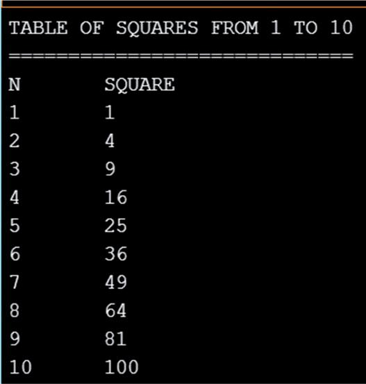
Figure 2.12 shows the program listing (Program: cylarea). Function area receives the radius and height of the cylinder as floating point numbers and returns the volume to the main program which then displays the volume on the Serial Monitor.
VOLUME OF A CYLINDER
// This program calculates and displays the volume of a cylinder
// Author: Dogan Ibrahim
// File : cylarea
// Date : June, 2023
#define pi 3.14159
float r = 10.0; float h = 15.0;
void setup()
Serial.begin(9600);
Mastering the Arduino Uno R4 ● 30
Figure 2.11 shows the output from the program, displayed on the Serial Monitor.
Figure 2.11: Output from the program.
//-------------------------------------------------------------------//
// ==================== //
//
//--------------------------------------------------------------------
{
delay(5000);
// Function to calculate the volume // float volume(float radius, float height) { float vol; vol = pi * radius * radius * height; return vol; }

void loop() { float cylinder;
Serial.println("Volume of a cylinder with r = 10 cm and h = 15 cm"); Serial.println("=================================================");
cylinder = volume(r, h); Serial.print("Volume = "); Serial.print(cylinder); Serial.println(" cm3");
while(1); // Stop the program }
2.3.4 Example 4: Centigrade to Fahrenheit
Write a program to receive the temperature as Centigrade, convert it to Fahrenheit, and then display it on the Serial Monitor. You should read the temperature from the keyboard.
Chapter 2 ● Arduino Uno R4 Program Development ● 31
} //
Figure 2.12: Program: cylarea.
Figure 2.13 shows the output from the program where the radius and height are set to 10 cm and 15 cm, respectively at the beginning of the program.
Figure 2.13: Output from the program.
Index ● 325 Index A Accurate clock 149 analogWave 242 Animation 267 Arduino Web Editor 23 ATmega328P 14 Attachinterrupt 82 B Binary counting 72 Blanking leading zeroes 124 Blinking LED 59 Bluetooth 276 Bluetooth BLE 277 Boards manager 25 Builtin RTC 216 Buzzer 174 C CAN bus 292 CAN bus node 295 CAN bus arbitration 297 CAN bus transceivers 300 CAN connectors 298 Chaser LEDs 67 Cortex-M4 15 Creating images 262 Current sinking 61 Current sourcing 61 Custom LCD characters 144 D DAC 241 Darkness reminder 164 DHT11 181 Displaying shapes 227 Door security lock 203 DS1302 207 E EEPROM 248 Espressif S3 15 External interrupt 80 F Factorial 54 Flame sensor 177 H HID 14 Humidity sensor 180 I I2C bus 136 I2C LCD 137 I2C ports 137 Infrared controller 311 Infrared receiver 311 Integer calculator 198 J Joystick 221 K Keypad 194 L LCD 136 LCD dice 154 LDR 146 LED dimming 255 LED matrix 226, 260 LM35 157 M Matrices 56 Melody maker 184 MFRC522 189 Multiplexed LED 114 P Periodic interrupt 218 Println 27 PWM 248 Q Quadratic equation 50
Mastering the Arduino Uno R4
● 326 R RA4M1 18 Random flashing 74, 103 Reaction timer 83, 128 Renesas RA4M1 14 RFID reader 187 RTC 207 S Scrolling text 142 Serial communication 280 Serial monitor 26 Servo motor 231 Seven segment LED 109 Shift register 100 Simulator 285 Sine wave 243 Sketch 23 Sound detection 175 Square wave 241 Stepper motor 237 T Tag ID 187 TCP 269 Temperature controller 161 Tilt detection 167 Timer interrupt 119 Time stamping 213 Traffic lights 89, 94 U UDP 269 USB-C 14 V Vibration tilt sensor 167 Voltmeter 160 W Watchdog timer 120 Water level controller 172 Water level sensor 169 WiFi 257 Wiring 12 WokWi 286
booksbooks
Mastering
the Arduino Uno R4
Programming and Projects for the Minima and WiFi
Based on the low-cost 8-bit ATmega328P processor, the Arduino Uno R3 board is likely to score as the most popular Arduino family member so far, and this workhorse has been with us for many years. Recently, the new Arduino Uno R4 was released, based on a 48-MHz, 32-bit Cortex-M4 processor with a huge amount of SRAM and flash memory. Additionally, a higher-precision ADC and a new DAC are added to the design. The new board also supports the CAN Bus with an interface.
Two versions of the board are available: Uno R4 Minima, and Uno R4 WiFi. This book is about using these new boards to develop many different and interesting projects with just a handful of parts and external modules, which are available as a kit from Elektor. All projects described in the book have been fully tested on the Uno R4 Minima or the Uno R4 WiFi board, as appropriate.
The project topics include the reading, control, and driving of many components and modules in the kit as well as on the relevant Uno R4 board, including
> LEDs
> 7-segment displays (using timer interrupts)
> LCDs > Sensors
> RFID Reader
> 4×4 Keypad
> Real-time clock (RTC)
> Joystick
> 8×8 LED matrix
> Motors
> DAC (Digital-to-analog converter)
> LED matrix
> WiFi connectivity
> Serial UART
> CAN bus
> Infrared controller and receiver
> Simulators
… all in creative and educational ways with the project operation and associated software explained in great detail.
Prof Dogan Ibrahim has a BSc (Hons) degree in Electronic Engineering, an MSc degree in Automatic Control Engineering, and a PhD degree in Digital Signal Processing and Microprocessors. Dogan has worked in many organizations and is a Fellow of the Institution of Engineering and Technology (IET) in the UK and is a chartered electrical engineer. Dogan is an author of over 100 technical books and over 200 technical articles on electronics, microprocessors, microcontrollers, and related fields. Dogan is a certified Arduino professional and has many years of experience with almost all types of microprocessors and microcontrollers.

All programs discussed in this guide are contained in an archive you can download free of charge from the Elektor website. Head to elektor.com/books and enter the book title in the search box.
Elektor International Media www.elektor.com