● This is an Elektor Publication. Elektor is the media brand of Elektor International Media B.V.
● All rights reserved. No part of this book may be reproduced in any material form, including photocopying, or storing in any medium by electronic means and whether or not transiently or incidentally to some other use of this publication, without the written permission of the copyright holder except in accordance with the provisions of the Copyright Designs and Patents Act 1988 or under the terms of a licence issued by the Copyright Licencing Agency Ltd., 90 Tottenham Court Road, London, England W1P 9HE. Applications for the copyright holder's permission to reproduce any part of the publication should be addressed to the publishers.
● The author, editor, and publisher have used their best efforts in ensuring the correctness of the information contained in this book. They do not assume, and hereby disclaim, any liability to any party for any loss or damage caused by errors or omissions in this book, whether such errors or omissions result from negligence, accident or any other cause.
● Tektronix® and all identified Tektronix trademarks and logos are the property of Tektronix, Inc.
● ISBN 978-3-89576-584-1 Print
● © Copyright 2024: Elektor International Media B.V.
Editors: Alina Neacsu; Jan Buiting MA; Denis Meyer.
Print: Tipoprint B.V. – the Netherlands
2
Table of Contents
The 500 Series............17
The 545 / 545B .............19
A True Monster.................19
Innovating Ideas ...............21
The Winning Decision ......22
New 530 Series ................25
545, The Monster.............26
The Futuristic 545............28
From 545 to 545B ...........30
CRTs and Phosphors........32
Delayed Sweep.................34
Tubes & Tubes.................36
Distributed Amplifiers .......38
Plug-in Architecture..........42
Me and the Monsters ........46
Its First Repair ..................49
Ceramic Strips..................51
Which & When.................52
Min vs. Max ......................54
Howard Caesar Vollum.....56
Howard’s Letter................59
The Scope Class ..............61
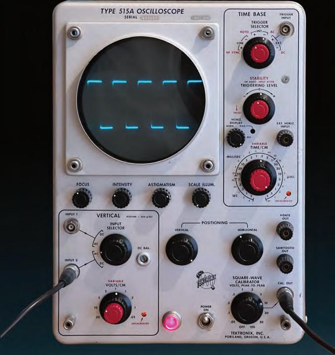
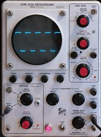
The 515A ......................63
Versatile and “Portable”....63
Specifications...................64
The Delay Line .................66
The “New” CRT................74
A Cyclone.........................80
The RM561A .................83
Beautiful, but… Dead!......84
The Repair Job.................88
Belle de Nuit.....................92
Hybrid Technology...........96
3B3 Dual Time Base .....98
So Similar, so Different ..107
3A1 Dual Trace ...........108
Conclusions ................118
The 300 Series...........121
First portables .............123
The 310A ....................125
Dream Book...................128
30 Electron Tubes..........130
310A ceramic stripes......132
The Rear Panel...............139
Old Style Details.............141
The 321A ....................143
True Jewelry...................143
True Portable .................144
Triple A ..........................146
Vs. Goliath......................149
A typical ‘60s..................151
The Nuvistor...................152
Power Supply .................154
Power Supply Circuit ......156
Memento Homo.............158
The 400 Series..........165
The 453 ......................167
Almost a Modern Scope .167
The Mythical 453............169
My 453A.........................170
Mod.(ification) 127C.......172
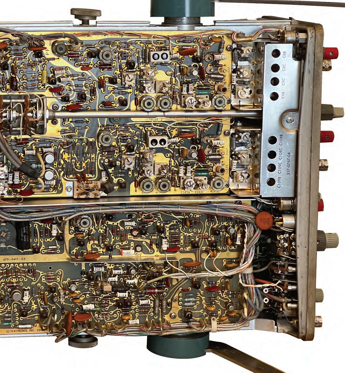
Top View ........................174
Golden Bottom ..............176
Side View........................178
Lever Switches ...............182
Need for Evolution..........184
Some other Details.........188
The 456/475 ...............191
They can travel with you.193
Panel Distribution...........195
A Unique Frame.............196
Built From Inside Out? ...198
New Components...........200
For any environment ......203
Air Conditioning .............204 Circuitries.......................206
Vertical Attenuators ........208
Vertical Amplifiers...........210
Trigger and Sweep .........214
Interface Board ..............219
Power Supply .................221
Crisp CRT Traces! ..........222
465/475 Bargain ............224
Recapping the 465 .........227
Fixing attenuators ..........229
Comparing to the 453....230
Conclusions ...................232
3
Table of Contents (cont’d)
The 7000 Series........235
Everything Changes! ......236
The models .................237
The Winning Idea ...........238
7000-Series e-book........245
The 5000 Series........247
Really the Worst?............248
The 5103N D11 ..........249
Tektronix Quality............256
Damned Torpedoes! ......258
5B10N.........................261
Time Base...................261
5A18N Dual Amp ........267
Really
The 11000 Series.......271
The
The
The
We
Mainframes..................283
The 11000 Revolution ....284
The 4-Traces Wall ..........286
Human Interface ............288
Autosetup
Automatic Comparisons.294 11400-Architecture ........296
Modularity ......................298
11403
Acquisition System.........306
Bewitched
Plug-ins
2400
Most
A
Analog
Quality
The
A
Those
Not the Worst!...268
Future on the Road .272
project..................273
ET Project ...............276
Must Do It ................278
1986, the Launch...........282
& Measur.......292
Boards ................302 Complexity .....................304
Self-Test & Diagnostics..316
Enhanced Accuracy........320
B-Side............................322
On the Market
Talking to It....................324
................328 Manuals..........................330
Using It...........................338
Small Repair................340
Another Monster.............337
A
Colors
Degausser
...........342 CRT
..............346 Performance...................348
.......................351 The 11A52 .....................352 Overdrive Recovery.........357 Seeking New World .....360
Series
Analog...365
A (too) Rich Family?
The 2000-Family.........367
.......367 Wikipedia Teaches .........369
Important Models...370
Different
Classification.372
Models
Manuals..377
Issues?
...............379
2465
....................383
great classic
................383
Cursors!...............385 Those Incredible CRTs ...387 New Approach................389 The Front Panel .............391 The Circuitry ..................392 Hybrid Circuits ...............397 The EAROM ...................398 Vertical Attenuators ........401 Attenuator ......................402 a Repair Story.................402 Nobody is Perfect ...........404 The Power Supply ..........406 Heat & Fans...................408 Other Boards .................410 Critical Parts...................412 Final Balance .................414 The 2445B ..................417 The “B” New Models ......418 A Different Logic ............420 Simpatico? .....................422 Main Board Bricks..........424 Right Side View ..............426 Counter Timer Trigger....428 Repairs and Roses..........430 The 2467 ....................433 The Last King................433 2400-Series Digital...435 The 2430 ....................437 2430, the First................437 Digital Breaks Out..........439 Ends and Starts..............441 4
Table of Contents (cont’d) Improved Construction...442 Main Board Bricks..........444 The CCDs ......................446 The Circuit .....................448 Front Panel ....................452 Mismatching...................454 I’ve Got It!.......................456 Does Tektronix Lie?........458 Averaging, Accuracy etc. 461 Calibration......................464 Probes Calibration..........466 Calibration/Diagnostics ..468 Accessories ....................470 Useful!............................473 The 2430A ..................475 Measurements................476 Main Board.....................479 Warning, do not Fry ICs .480 Accessible ......................483 You Can Open It ............485 Power Supply .................487 Power Supply Repair ......488 The Rear Panel...............490 The Missing Click ...........492 The 2440 ....................495 Main Board.....................497 Hi-tech Inside.................498 Processor Board.............500 Sunk by Torpedoes ........502 Performance...................506 Collateral Damages ........508 The Jokey 2431L ...........511 The 2431L ..................511 Main Board.....................513 Display Board.................515 Processor Board.............516 Dallas Memories.............518 Simplified Rear Panel .....520 Fixing the HV Board .......522 The 2200 Series........525 The 2230 and 2221.....527 The Two Worlds Heroes.527 Become a carver ............529 The 2221 .......................530 Out of the Box................533 2230’s Secrets ...............534 Main Board Bottom........537 Attenuators ....................538 Suicidal Diodes ..............540 Fixing 2230’s PSU..........544 Lost Potentiometers .......548 A better solution.............553 End of the Story .............554 Lessons Learnt...............556 Finished .........................558 2230 Backlash! ..............560 Prices Today................568 2000-Series notes .......569 Last-minute Bug..........570 New Knobs..................572 EPROMS .....................574 Manuals.......................576 Years and Versions ......578 Size and Weight...........580 Acknowledgments ....583 The Show Goes On! ..587 vv 5


WARNING!
Very dangerous voltages exist inside every oscilloscope, even after it is switched off.
All the technical information contained in this book is intended only for EXPERT TECHNICIANS, fully aware of the connected risks and their management.
If you are not an expert, don’t try even to open them under any circumstance, and always refer to the applicable documentation for their use.
6
Automatic Oscilloscopes?
Oh, well, you will answer, every oscilloscope is automatic! But it didn’t use to be always so. Almost all that we use in a modern oscilloscope had a first: the first trigger, the first sweep, the first delayed sweep, the first dual trace etc.; and all these “firsts” have been signed by Tektronix. Tektronix (shortform “Tek”) is a large company, founded in 1945 by Howard Vollum and Jack Murdock, building electronic instruments. But for my generation, Tektronix “is” the oscilloscope itself.
In this book, we will retrace the history of this invaluable instrument, crucial for our scientific evolution, through examining many products of this great American firm.
Many others came after Tek in the oscilloscope market, and Tek’s activity has not been limited to oscilloscopes, but, for us, the word Tektronix is and will remain the synonymous to oscilloscope.
Why this book? Simple: I love old electronic instruments. Old equipment is extremely charming, either because it was part of our lives, either because we still have a lot to learn, not only from the technical point of view, from the old, “true” Tektronix, Hewlett & Packard, and other giants who literally wrote the history of electronics. Wonderful classic instruments, which today we have the pleasure and the privilege to preserve for the future.
I wish to thank Mr. Denis Meyer,senior editor and producer at Elektor, who guided the long process of converting my amateur work into a professional product, with extreme kindness and patience.
I hope that our efforts will be appreciated by others who, like me, like these witnesses of a distant era.
Giovanni “Gianni” Becattini

To my wife and my family
7
500 Series
5000 Series
11000 Series
2400 Analog
2200 Series
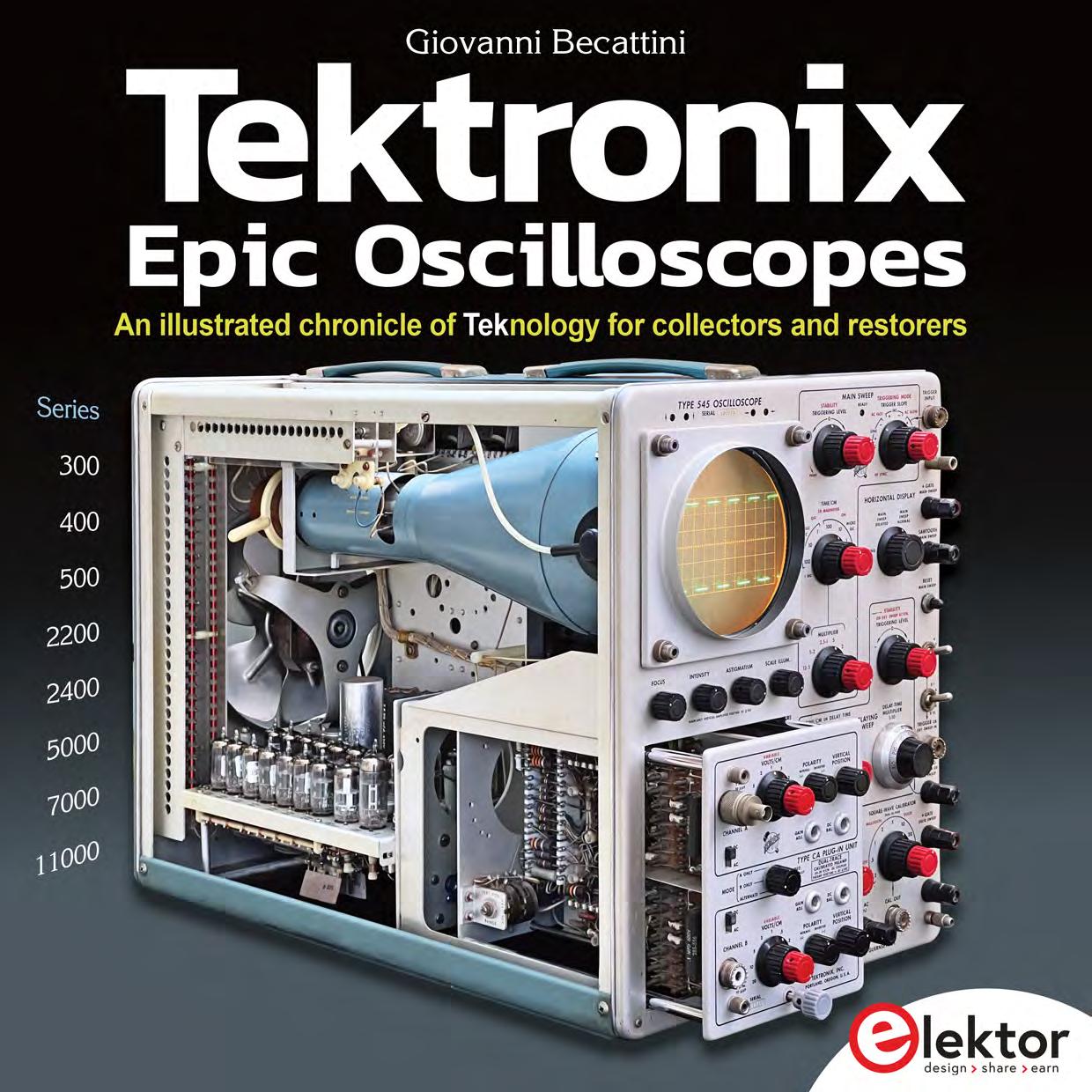
Tektronix Epic Oscilloscopes
300 Series 400 Series
7000
Series
2400 Digital 14
545, 545B, 515A, RM561A
310A, 321A
453A, 465, 475
7704, 7904, 7844, 7603, 7633, etc.
5103N, 5A18N, 5B10N
11301, 11401, 11402, 11403, 11A52
2465, 2445B
2430, 2430A, 2440, 2431L
17
121
2221, 2230
165
235
247
271
365
435
525
225
225
Page
Page
15


16
545, The Monster The 515A, Versatile The RM561A, in Rack 63 83 19 17
The 500 Series The
A True Monster
You cannot do that
“You cannot do that” I thought, “You are writing a book about Tektronix, and skip your first love”. This thought had been floating around in my mind for a while, but just a few days ago I stumbled upon not
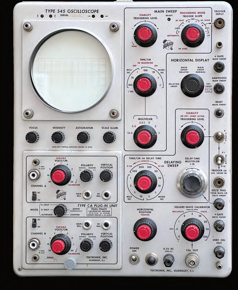
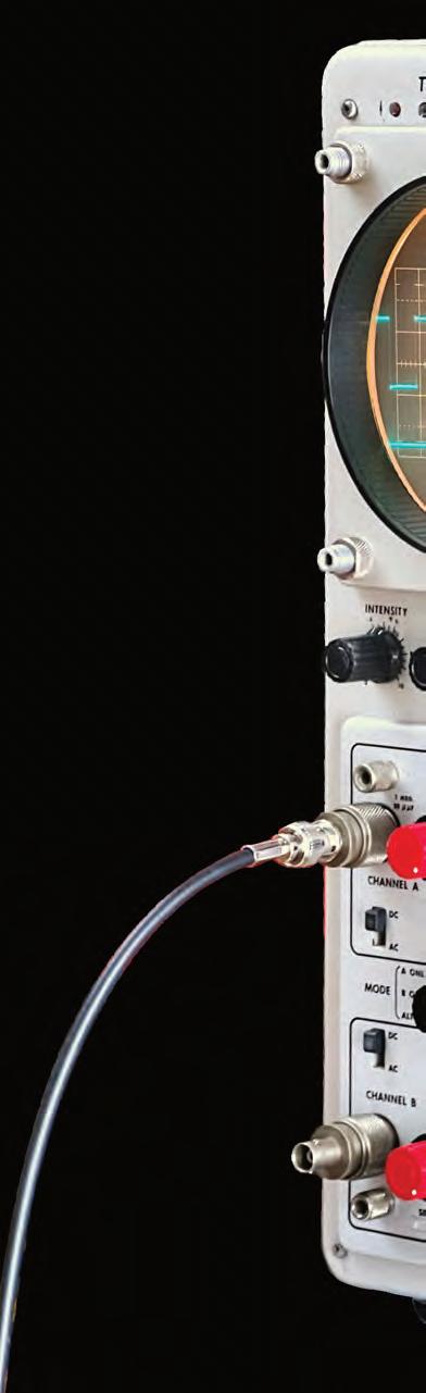
A little graphical license
The 545 is a masterpiece deserving to dominate on the cover of this book. However, its photo is clearly faked, since no 545 can ever work with the plug-in unplugged. In addition, my 545 still lays in the hospital with a reserved prognosis, so, to switch on its display, a photo editing “transplant” from the 545B was required. You could discover my little trick also from the CRT graticule: the 545 should be four division high, but that in the photo is 6, i.e., the 545B’s one!
18
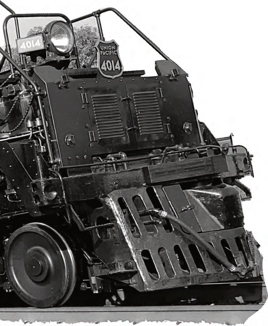


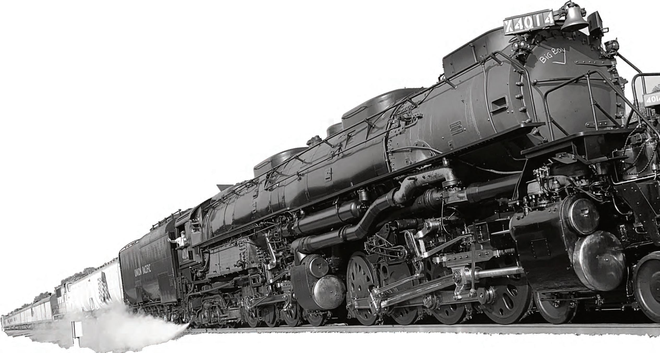
19 500 Series The 545 / 545B Locomotive photo: from Di Fan Railer - Opera propria, CC BY-SA 4.0, https://commons.wikimedia.org/w/index.php?curid=109558972 1955 19
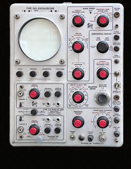
545, The Monster
The 535 was a beautiful instrument, but limited in its performance at 10-MHz bandwidth. John Kobbe, one of the CRT designers, proposed with the idea of a new circuit capable of running two or three times faster than the 535, by using a distributed amplifier, driving a balanced delay line straight to CRT’s vertical deflection plates, even if limiting the vertical display area to four divisions. The Type 545 was born; substantially, it was a 535 with beefed up bandwidth. Symmetrically with the 531, the 541 was the same model with just one time base.
The added delaying time base added was allocated in the available space, and made hinged to allow maintenance.
26
The 545 / 545B 27
From 545 to 545B
A breakthrough, but…
Even if limited in the viewable area to only 4 divisions, the 545 was a breakthrough, made possible by Tektronix’ investment in CRTs’ development. The 545 was a real top gun, with its (then) fantastic 30MHz bandwidth (33MHz with a 50MHz plug-in such as Type 1A1), the double time base and the plugin architecture, even if limited to the vertical amplifier. The 545’s prices from the 1955 catalog confirm it: the mainframe cost 1,450 USD, and you had to add a vertical plug-in, like the CA, for 250 extra USD: a total of 1,700, which, according to the Internet converters, correspond to 19,244 USD today, or, here in Europe, 20,250 euros… 675 euros/MHz!
The 545, with updates in the A and B versions, remained in production from 1955 to 1974.
By the way: the question if the time base had to be a plug-in or not remained topical for a long time, and many years later, with the 11000 Series (page 271), again it was established that it was useless having pluggable time bases; the history’s jokes…
The 545B
To have a 30 MHz bandwidth, the customers accepted that small viewing area, but, clearly, the wish to have a larger display was urging, and we can understand that the designers at Tektronix’ focused on improving this point.
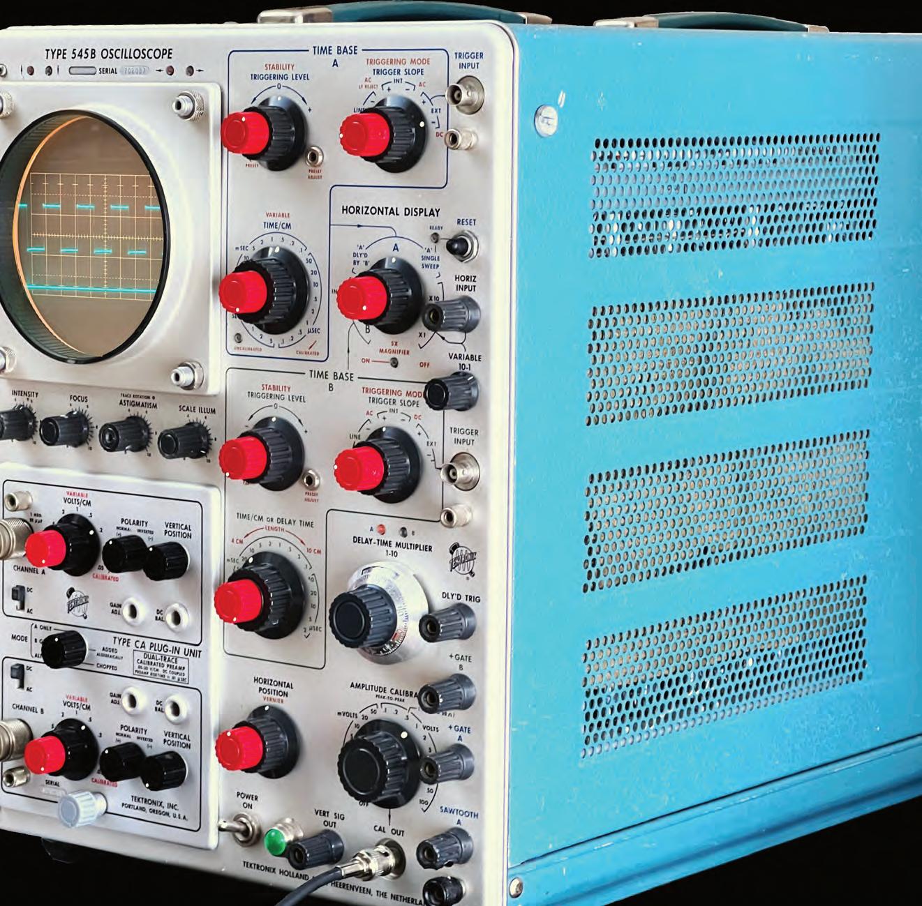
We had to wait until 1964 to see the Type 545B, here presented as well, which extended to 6 divisions the trace height; not really a leap forward, only two extra divisions in 9 years (nevertheless 50% more viewing area). Evidently the solution was not easy, and the CRT technology was still under development (the 1959 545A had only a difference in the front panel controls, not any major circuit design changes. The main improvement was to replace a pair the 8-position Time/Div and 6-position multiplier with a single 24-position switch, freeing up front panel space for a Time Base B Trigger [TekWiki]).

30
Air hungry
The 545Bs, like the 545s and 545As, need lots of fresh air to cool the scope internals, where as much as 600 W is dissipated and must be extracted. The ample grilles must always be kept free from obstructions.

The 545 / 545B
31
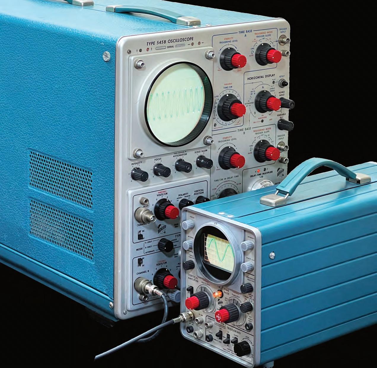
48
Here above, the big 545B is celebrating with the the small 321A its return to life.

Its First Repair
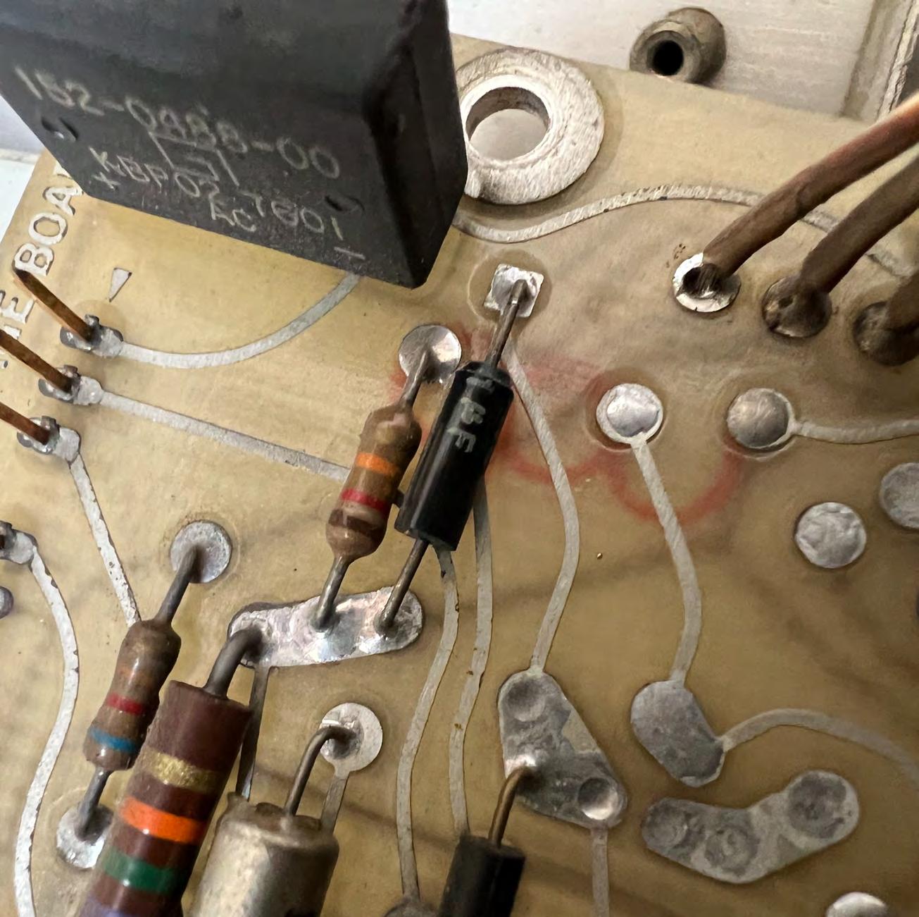
Well, not the first ever, but the first by me. The problem is that my 545B switches on, but it cannot trigger the signal, and the CRT is blurry due to the excessive jitter. All the voltages are almost good in value, but the +225V has a giant ripple: 10 V instead of 5 mV.
The filter capacitor has been replaced with a new one by someone else. But… look, it is not soldered! Probably the shipment broke the joint. I resolder it, and…the ripple is reduced but is still 1.5V.
I discover that I am working on a wrong schematic, downloaded from Internet, but luckily, I have the printed one (my 545B is more recent). For the 500 Series, Tek gave only the schematics and not the component map, complicating the repair. I check the 6080 double power triodes that regulate the voltage with my TV-7/U tube tester, and find out that one of them if faulty. I replace it, as well as the filter capacitor, which was too small. Again, the ripple is lower (800 mV), but still in excess. At this moment, the instrument works for the photos, but now I can't help but solve the problem…
In the beginning I am deceived by the +225V 200 mA current absorption, which seems excessive. Is the ripple due to an overload? It is easy to measure the current: every voltage has a resistor in series for this; for the +225V it is R700. It's a red herring; to discover that, I had to section all the +225V line, a long work, which finishes in nothing: the problem is not the load.
In fact, the 545, with its 20-tube vertical amp, drains more current from the whose regulator has two 6080 triodes in parallel. The 545B itself as much as 80 mA from the +225V, so, in the 545B, one 6080 triode has been moved from the 350V to +225V section.
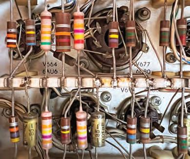
After a careful study, I finally discover the true culprit: a precision resistor (R681, 247K) changed its value to 295K (the resistance value increase is a typical problem in old electronic stuff). In the study, I was helped by the 7000-Series experience. These old voltage regulators use a similar circuit based on differential amplifiers; they just use tubes instead of transistors.
She is the culprit, circled in red here on the left, Why “she”? Because in Italian “Resistenza” is feminine…
The 545 / 545B 49
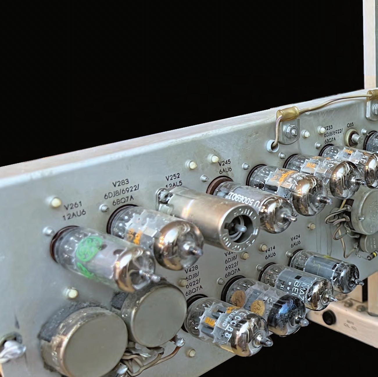
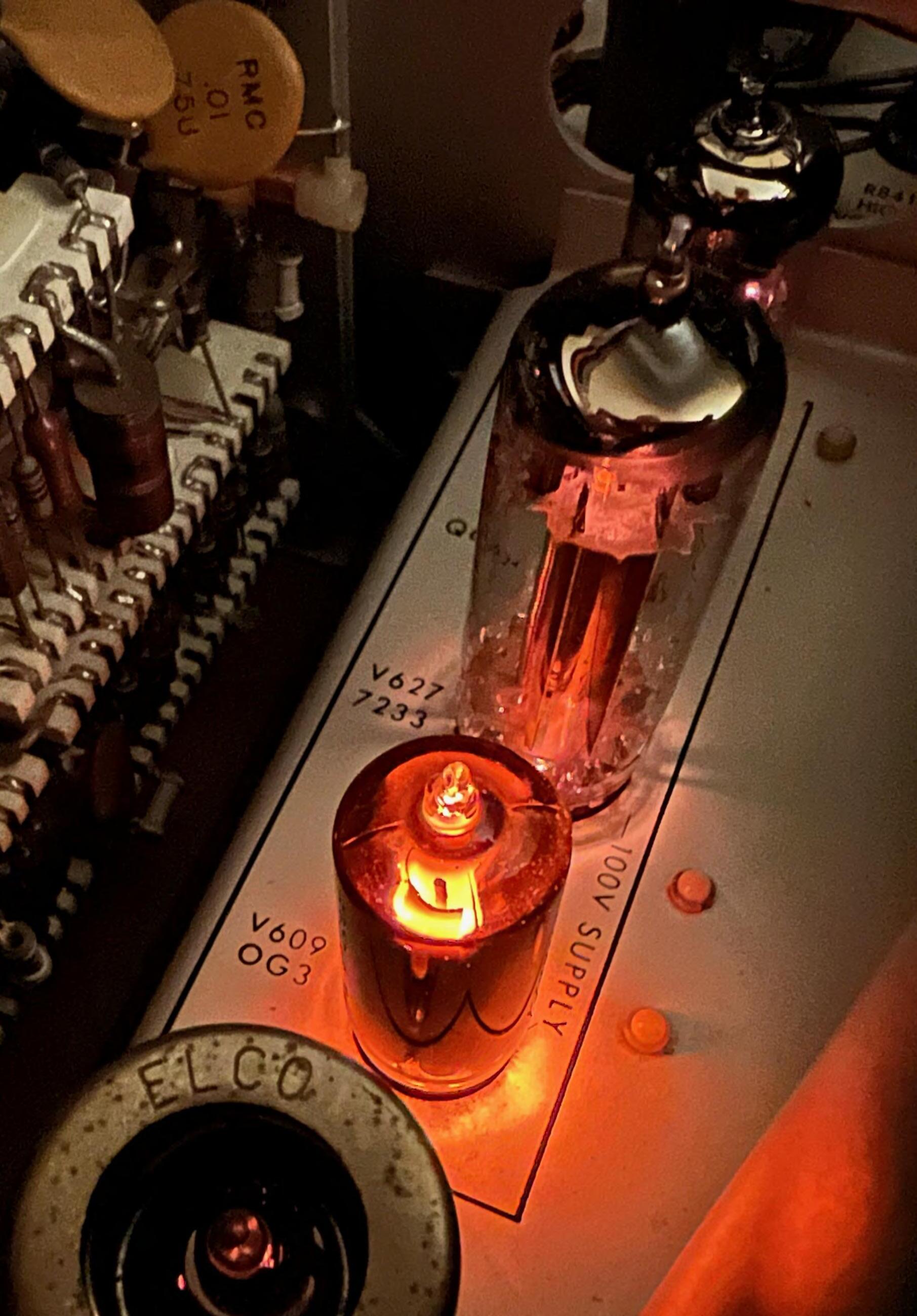
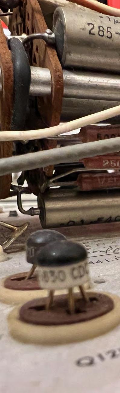
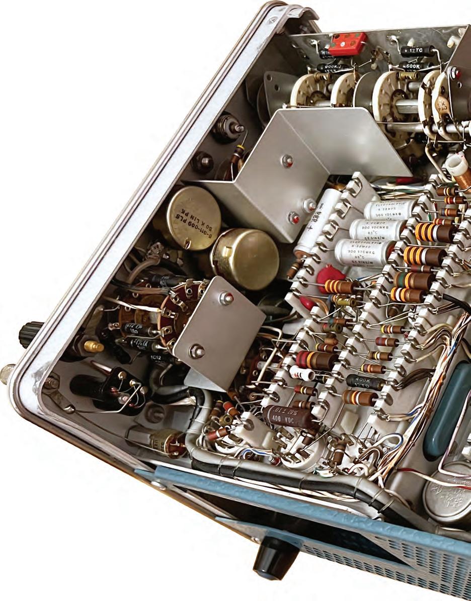
Hybrid Technology
96
96
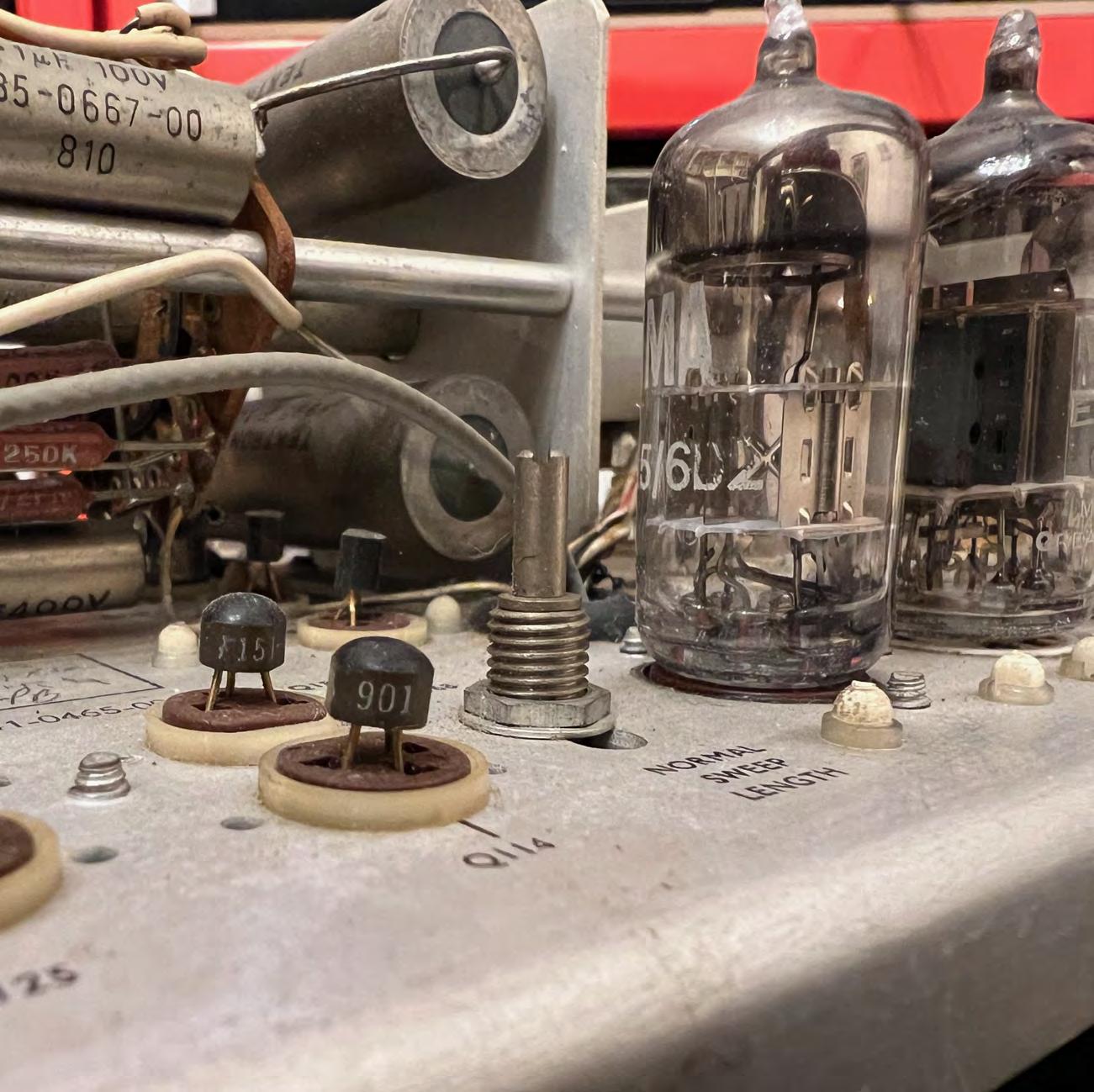
Here in the photo, is something I've never seen: a hybrid construction, with transistors mixed with tubes. Even more amazing, the transistors mounted like the tubes, using a large socket. PCBs are still far from arriving, and the designers continued with sockets like they used to do with the vacuum tubes. I find this picture irresistible!
97
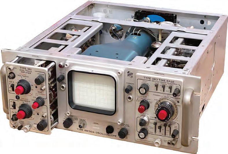
The RM561A
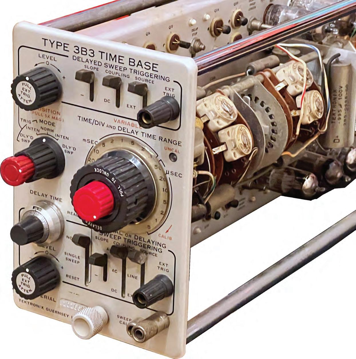
3B3 Dual Time Base
General
The Type 3B3 Time Base Unit is a plug-in time base generator designed for use with Tektronix Models 561A, RM561A, 564, 567 and RM567 oscilloscopes, already present in the 1962 catalog. The Type 3B3 provides normal or delayed sweeps at 20 calibrated rates from 0.5 µs/div to 1 s/div. In delayed sweep operation, the Type 3B3 gives continuous calibrated sweep delay from 0.5 µs to 10 s after receipt of a triggering impulse.
Note that the 561 went beyond the 535/545: the plug-in was no longer the vertical channel but also the time base.
Sweep Rates
•Both normal and delayed sweep rates from 0.5 µs/div to 1 s/div in 20 calibrated steps. A variable control provides uncalibrated sweep rates between steps and also extends the slower rate to approximately 2.5 s/div. Calibrated sweep rates for both normal and delayed sweeps are typically within 1%, and in all cases within 3% of the TIME/DIV and DELAY TIME RANGE switch settings.
Sweep Magnification
•The display can be magnified 5 times, extending both the normal and delayed sweep rates to 0.1 µs/div. Sweep rate accuracy with the 5X magnification remains within 5% of the TIME/DIV and DELAY TIME RANGE switch settings.
Sweep Delay
•The calibrated sweep delay is continuously variable from 0.5 µs to 10 s. Delay accuracy is 1% of full scale reading, and delay time linearity is within 0.2% of full-scale from 5 µs to 2 s of delay.
•Time jitter is less than 1 part in 20,000 of the maximum available delay interval.
Single Sweep
•All modes of operation can be displayed as a single sweep for photographic recording.
98
The RM561A 99
310A ceramic stripes
Ceramic strips
Read at page 51, where you can find some hints on how to solder them correctly.
Obsolete in 1971
In the 1971 catalog, the 310A is listed among the “limited-demand instruments”, i.e., it was by then obsolete, and Tek said: “The Type 321A or 323 is recommended as a replacement for the Type 310A”.
132
310A 133
The
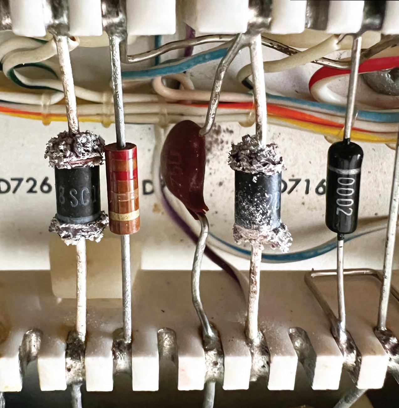
Memento Homo
“Memento homo, quia pulvis es et in pulverem reverteris”, the Scriptures say (remember man, that you are dust and to dust you will return). That must be true also for the diodes, or, at least, for those used in my 321A. When my 321A arrived home, it was not working. The trace was present and could be moved on the screen, but it was absolutely deaf and no signal could be displayed.
The seller seemed like a good person to me, and probably was not aware of the problem. In any case,
I was very happy with the purchase, so I started trying to fix it. Terrible thoughts: the Nuvistor? Some unobtainable transistor?
I first checked the Nuvistor voltages, and I discovered soon that the +45V plate voltage was absent. I went to the power supply section, and noticed that all the diodes had developed a strange powder at their ends (see the photo). The +45V rectifier was even physically broken. I replaced it, and immediately the 321 started working correctly.
I have never seen an effect like that. Currently, I am not replacing the other diodes, which work well, but probably I should. Note that all the components are still the original ones, even the electrolytic capacitors, so I don’t fancy changing them, if not necessary (update: another diode failed, so I replaced the lot).
158
The 321A 159
Golden Bottom
More than a facelift
We said “a remake”, because the 453A goes beyond a simple facelift, and the differences with the 453 are rather important.
Change for the better used to be a tradition at Tektronix. New components, new techniques, new applications and problem fixing, are factors that continuously prompted them to enhance their products.
Often, the changes were small and went unnoticed by the average user. Sometimes, however, the changes are substantial, resulting, in essence, in a new product.
Two standards in the portable oscilloscope field, the 453 and 454, underwent such a transformation, to be rebaptized 453A and 454A.
New CRT, new usability
With respect to the previous versions, a glance at the front panel reveals both instruments have big new CRTs. The screen size has been increased to 8 × 10 div providing 33% more viewing area.
The accelerating potential on the 453A is raised to 14 kV so that viewing low pulse repetition rates is possible even in adverse ambient light conditions.
176
The 453A 177
2 1
192
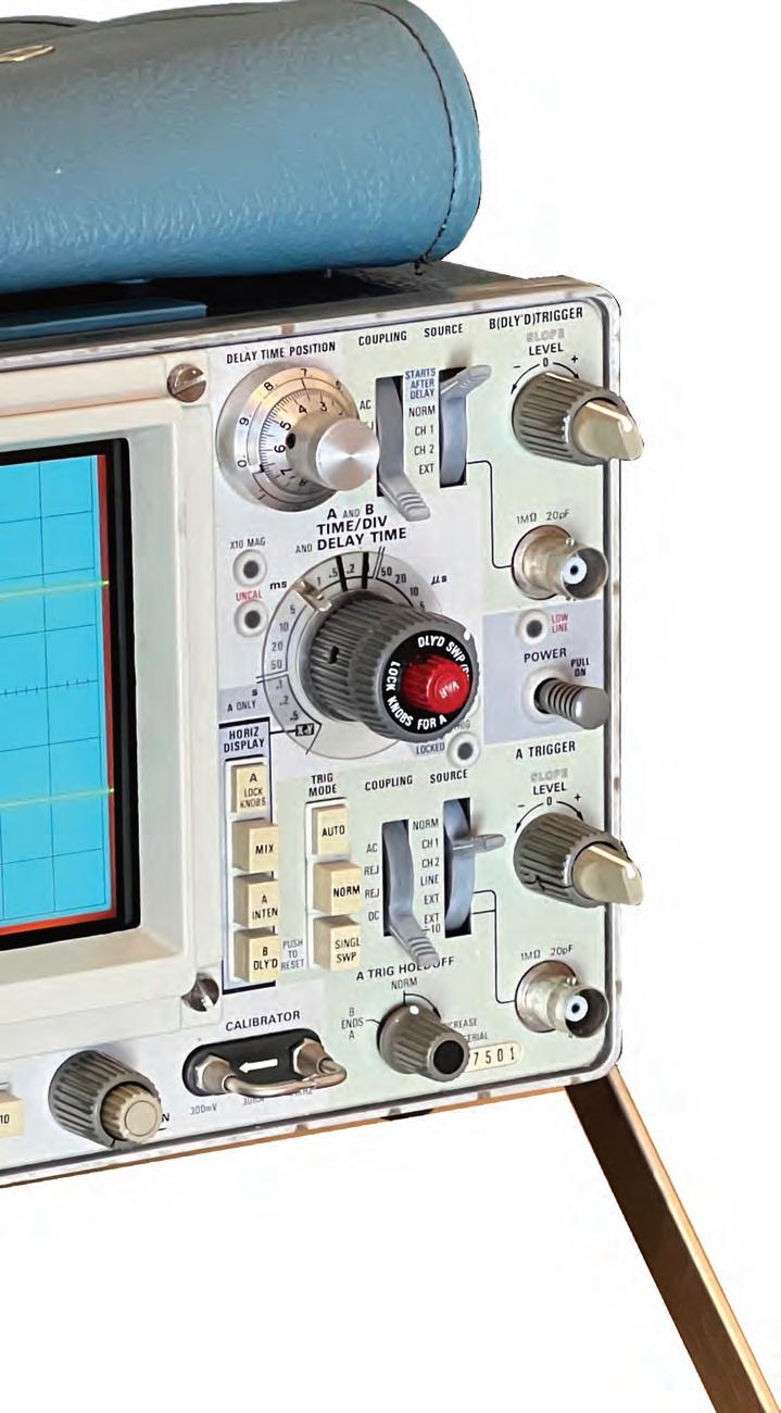
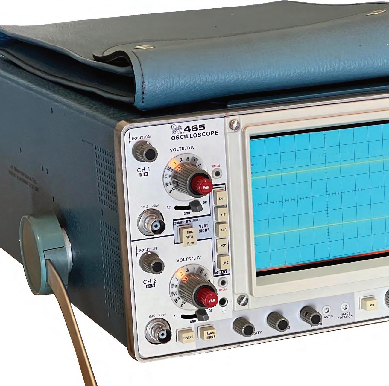
They can travel with you
Let’s start with a quick look at my surviving 465, a portable 100MHz dual-trace oscilloscope with dual timebases, introduced in November 1972, possibly based on the same technology as the 7000 Series. It is all solid-state except for the CRT. The 465 was very popular and Tek made them for quite a few years. According to TekWiki, microfiche records tell about 37 variations of the 465.
I consider it something like a portable version of the 7603, with 7B53A and 7A26 plug-ins (without readout, but with a smart backlit V/div knob, a poor man’s substitute for the readout…).
The delaying time base uses a knob similar to the 7B53 7000-Series plug-in, but with a slightly different logic: instead of a not-always-intuitive pull & push, the 465 allows to explicitly request what you want to see, by means of four dedicated buttons. Today, the 465 is still very practical and pleasant to use. It’s no surprise that it was so successful when introduced. If you are lucky, you can still find 465/475s on eBay for 40-50 euros.
My 465, after all these years, is still well calibrated and outperforms the declared bandwidth by more than 30%.
1972 The 465/475
193
Damned Torpedoes!
So a crucial moment has arrived. As usual, I start checking the voltages for a short time, to limit damages in case something is wrong.
Ah… the -30V is just zero… Let’s stop everything and investigate. I am concerned that the problem is on the high-voltage/multifunction board, which is very difficult to unmount. But I also note that the30V goes also on the storage board (the one that you can see here below out of the box). I still have not the schematic (on TekWiki there is only the 5111A, that is different), but it was not too difficult to understand that the problem was in a 1uF 50V “small torpedo” capacitor, similar to those that we had to fight in the 2000 Series (big photo on the right). I replaced it with a Tantalum; the -30 is OK and I am ready to go further with the tests.
258

5000 Series 259

1986 1974 336
Another Monster
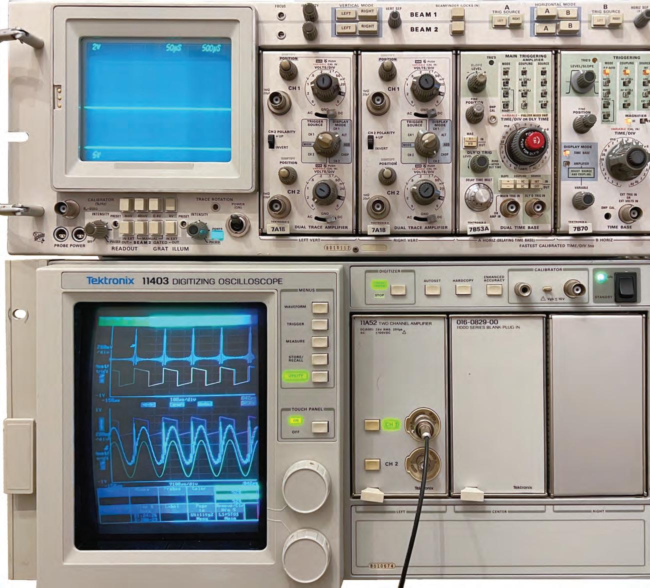
As you know, at this point, I like these machines, and probably suspect that I wrote all that above just to arrive at this point…to tell you about my 11403, which you can see here together with the R7844. With the 11000 Series, the “R” versions disappear: two brackets, and the base model goes into a rack.
A wonder machine
I have found the 11403 a wonder machine, with its color touch screen, an lot of functions, and very high performances (1 GHz), even if for repetitive signals only. The 11403, as already mentioned, appears for the first time in the 1990 catalog.
Too few knobs and buttons
Initially I didn’t like it: it had too few knobs and buttons, but when I have looked more carefully at these new (in 1986) oscilloscopes, I was hit, so, when I had the opportunity to buy an 11403 at a fair price, I took it on the fly.
Truelove
After having opened the cabinet and seeing all those wonderful boards full of ICs, the initial attraction suddenly became love. It is the most complex object that I own, or at least on par with the Digital Equipment PDP-8.
Its condition is good: it has some problems in the delayed time base and the monitor was driving me mad to work properly (in the photos you can see a visible convergence problem on the right side). It still had the sealing labels from its last calibration, probably in 1999, while the 11A52 has the original Tektronix seals.
How old are you?
Tektronix serial numbers cannot help us detect the construction year of a gear, but we can rely on the date printed on the ICs. In my unit, I could find ICs of 1990. The 11400 have however two non-reversible counters that can be quested by the remote interface, with the commands “UPTime?” and “POWeron?”, that in my case report 19397.5 hour and 4671 cycles. In thirty-one years, it worked a mean of 625 hours/year. More probably, it was part of a test equipment that worked 2/3 thousand hours per year before passing to other kind of work, and finally to a shelf.
11000 mainframes 337
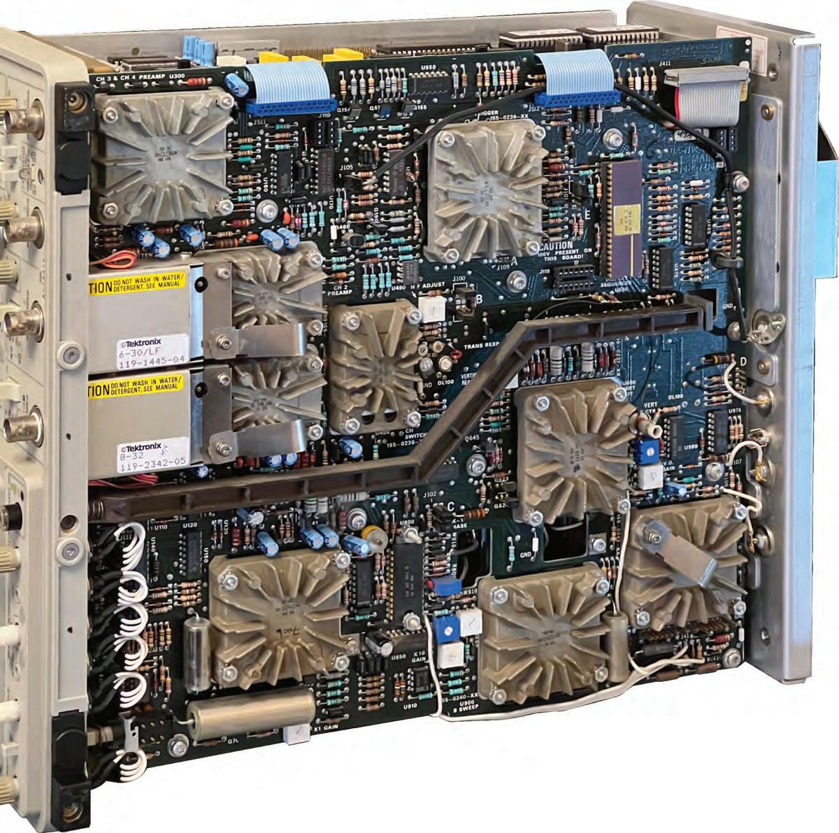
New Construction Approach
We already talked about the inspiring principles of the new 2000-Series oscilloscopes, adopted and executed with volume production in mind.
In reality, there is not only one board; other boards are required, and not all are large, but the very dense main board concentrates most of the critical analog parts and is designed to be easy to produce and as well test.
The base components of the main board are hybrid circuits (HICs). We have already seen them in the 11000 Series, but here, and in subsequent models, they become the fundamental construction brick.
It is a very nice solution: the most critical circuits are concentrated in a relatively small die-cast aluminum module, that offers many advantages (we will talk about this technology more deeply on the next pages).
Here in the picture we can count as many as nine HICs:
• Channel switch
• Horizontal, Vertical and Z-axis input and output amplifiers
• CH3 and CH4 preamps
• A & B triggers
• A & B time bases
The HIC were surely a good solution also for the maintenance. Helped by the many automatic procedures embedded in the scope software, it is not too difficult to identify a wrong HIC, that can be easily replaced in minutes. We are less happy today, because they are rather expensive, sometimes more so than the entire instrument. See page 397 for more details about the HICs.
388
New Approach
The 2465 389
Main Board Bricks
The 2445B main board is very similar to the 2465 and similarly heavily relies on building blocks, such as hybrids and custom ICs.
The following are used in the 2445B:
• U100, U200: 153-2235-03 channel preamp;
• U300: 155-0238-00 external trigger preamp;
• U400: 155-0236-00 vertical channel switch;
• U500: 155-0239-02 A/B trigger;
• U600: 155-0237-00 vertical output amplifier;
• U650: 155-0244-01: system
• U700, U900: 155-0240-00 sweep generator
• U800: 155-0241-02 system logic interface
• U950: 155-0242-01: Z-axis & autofocus amplifier
These blocks are the repairer's nirvana, because they make the repair easier, but can be difficult to find and rather expensive, so I prefer when the fault is in a capacitor or a transistor, even if it requires more time to be located.
A difference with respect to the 2465 is represented by the two connectors where the gray flat cables visible in the photo end (previously there were only normal pins). The flat cable is used to connect the options board, as we will see better soon.
Attenuat Extern trigger preamp U300 424
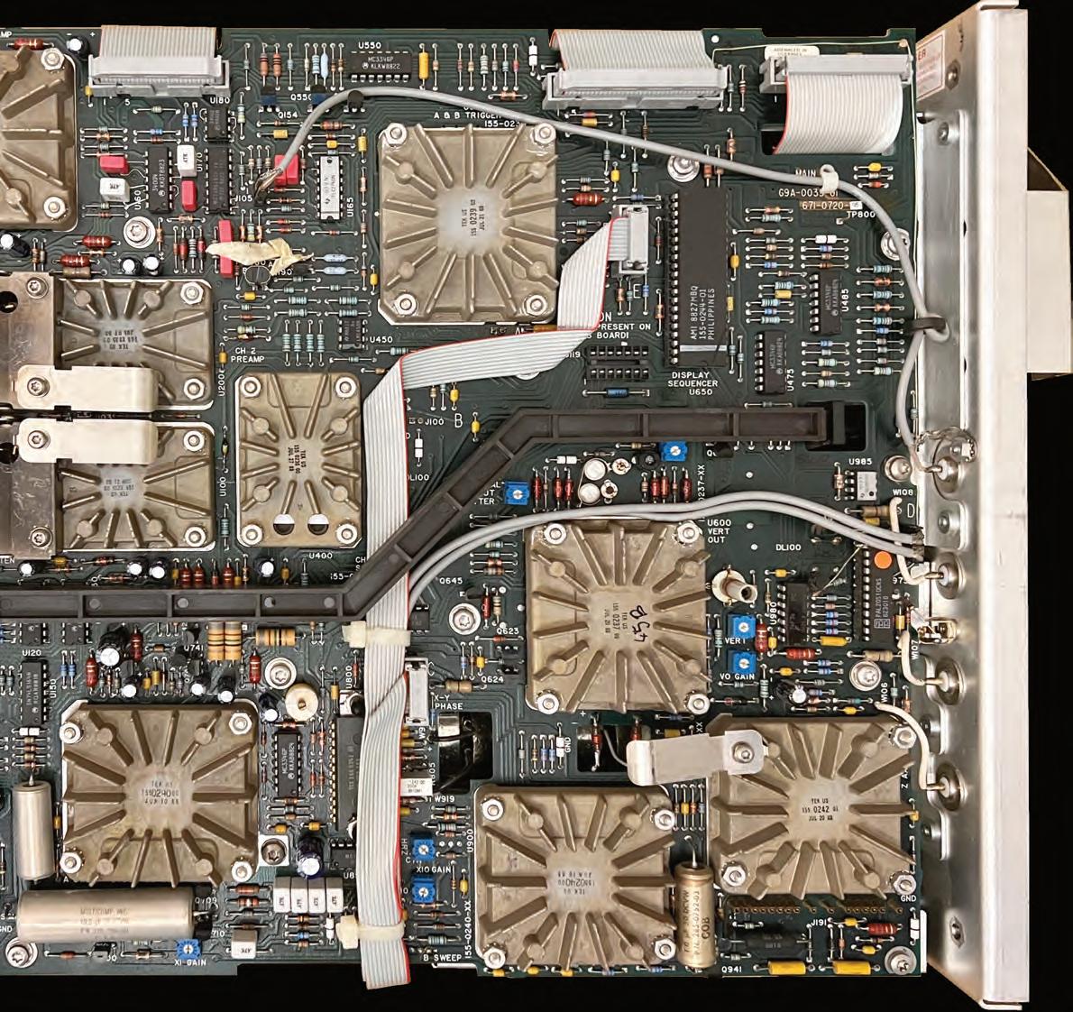
Preamp Preamp Vert chann. switch Vertical output Sweep generat. Z-axis autofocus Horiz. output Sweep generat. Phase clock array A/B trigger Extern trigger preamp U200 U100 U500 U600 U650 U950 U900 U700 U800 U400 The 2445B 425
Calibration and


Calibration/Diagnostics 468
Diagnostics
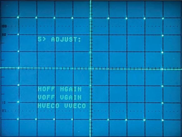
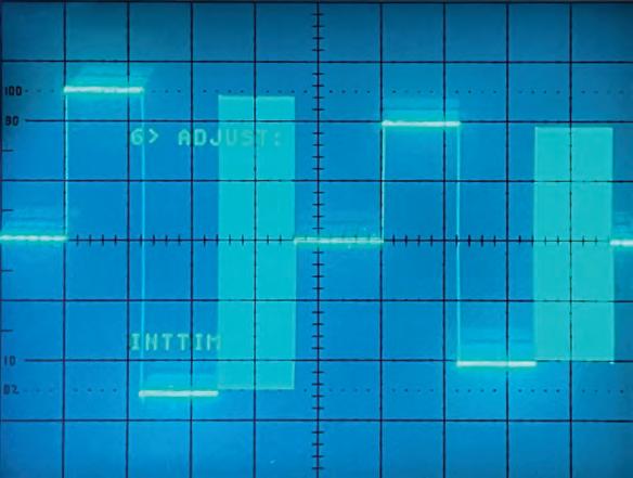
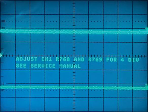
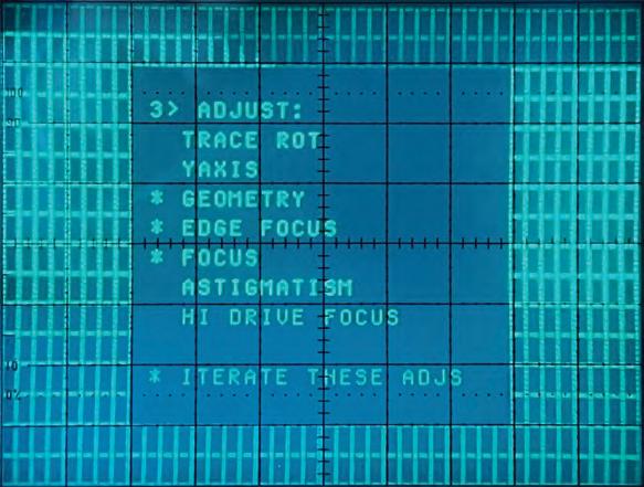
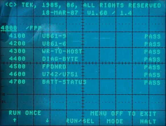
The 2430 lays the foundations for all the subsequent models with innovative concepts that go beyond the first user experience. These new oscilloscopes are conceived not only to reduce production costs, and thus the end user price, but also the cost of ownership, making routine calibrations and repairs easier and more reliable in most cases, without a dedicated test fixture.
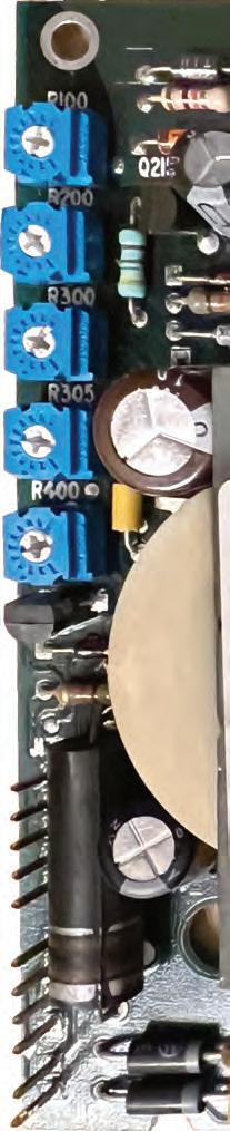
We already saw on previous pages that the attenuators and triggers calibration, almost fully automatic. Another menu, called ADJUST, allows many adjustments according to the instructions supplied by the scope itself, up to saying which trimmer you have to turn (see photos on the left).
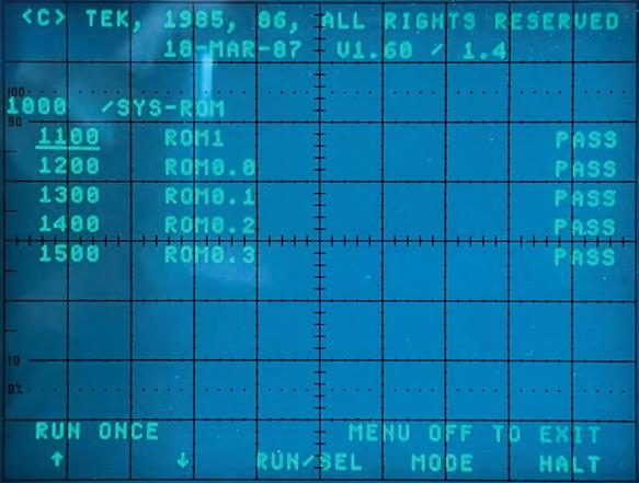
A rich set of diagnostic routines is executed at startup and they can be recalled by the maintenance operator (examples on the right). The impression is that Tektronix wanted to test everything that could be automatically tested. The routines can also be iteratively executed.
A precious help also today, for us little restoration enthusiasts.
The 2430 469
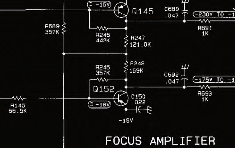
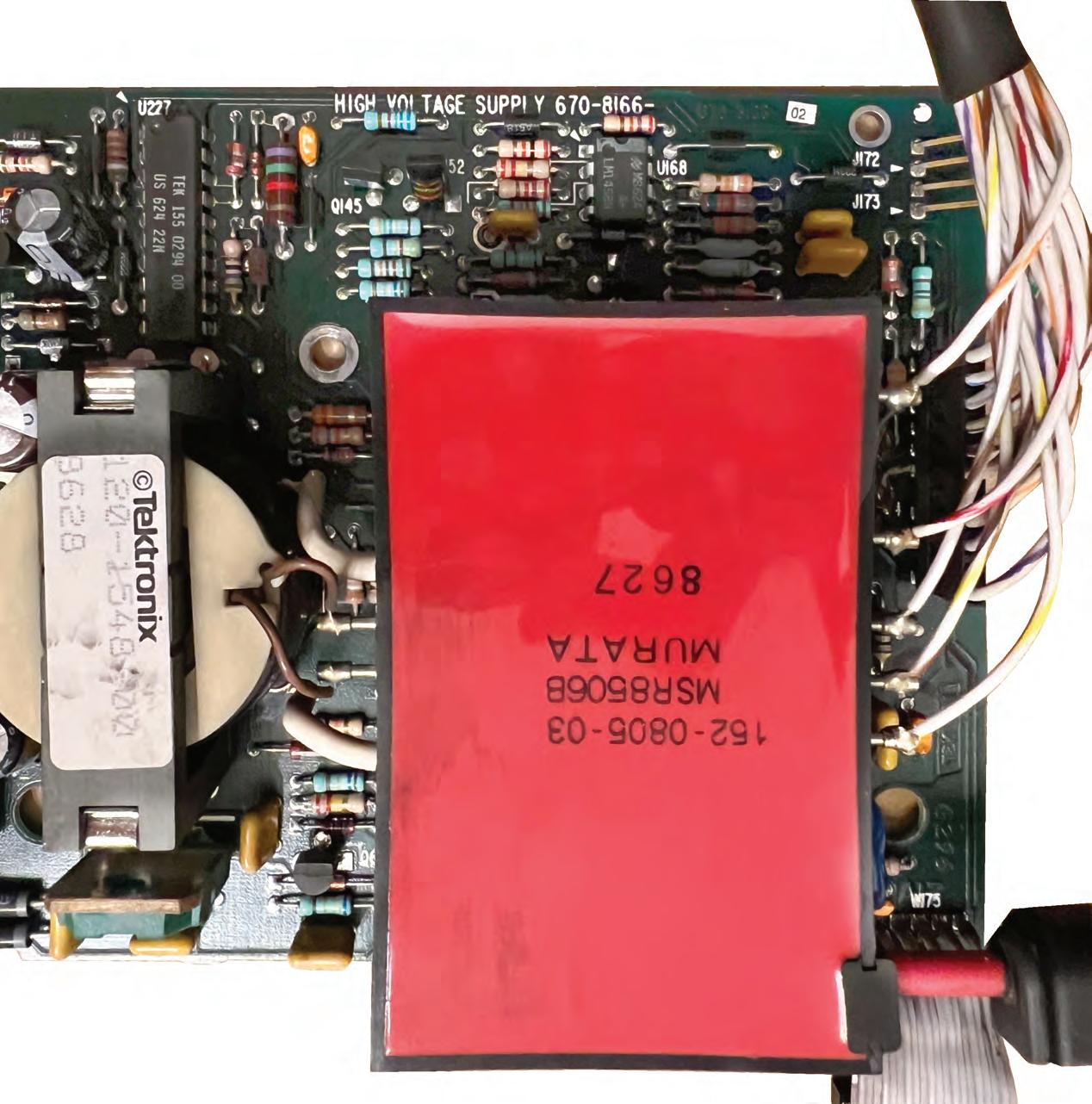
Fixing the High Voltage Board
Initially, the 2431L produced a totally out of focus screen. The manual is well written in this part, so checking voltages and signals it was not too difficult to discover that R248 was open. I replaced it, and it worked.
After the replacement, I found that:
• a cold start is required;
• a CRT visual calibration must be performed.
See “Calibration” page earlier in this section (page 464).
Fixing the HV Board
522
The 2431L 523