Giovanni Becattini
I'MGIANNIANDIHAVEN'T REPAIREDANOSCILLOSCOPE FOROVER9DAYSAND 11HOURS...

● This is an Elektor Publication. Elektor is the media brand of Elektor International Media B.V.
● All rights reserved. No part of this book may be reproduced in any material form, including photocopying, or storing in any medium by electronic means and whether or not transiently or incidentally to some other use of this publication, without the written permission of the copyright holder except in accordance with the provisions of the Copyright Designs and Patents Act 1988 or under the terms of a licence issued by the Copyright Licencing Agency Ltd., 90 Tottenham Court Road, London, England W1P 9HE. Applications for the copyright holder's permission to reproduce any part of the publication should be addressed to the publishers.
● The author, editor, and publisher have used their best efforts in ensuring the correctness of the information contained in this book. They do not assume, and hereby disclaim, any liability to any party for any loss or damage caused by errors or omissions in this book, whether such errors or omissions result from negligence, accident or any other cause.
● Tektronix® and all identified Tektronix trademarks and logos are the property of Tektronix, Inc.
● ISBN 978-3-89576-648-0 Print
● © Copyright 2024: Elektor International Media B.V.
Editors: Glaucileine Vieira; Jan Buiting MA; Denis Meyer.
Print: Tipoprint B.V. – the Netherlands

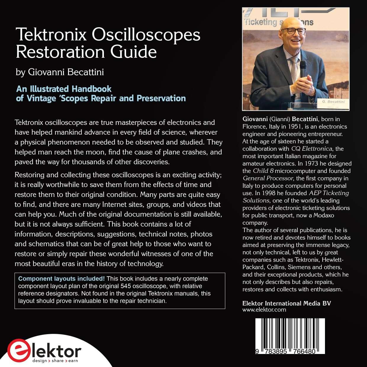
Tektronix oscilloscopes are true masterpieces of electronics and have helped mankind advance in every field of science, wherever a physical phenomenon needed to be observed and studied. They helped man reach the moon, find the cause of plane crashes, and paved the way for thousands of other discoveries.
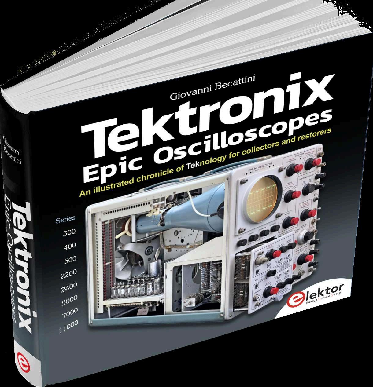
My successful book Tektronix Epic Oscilloscopes, published by Elektor, describes many models of them, from the early fifties to the nineties, with their history, data, descriptions, and many photos.
Restoring and collecting these oscilloscopes is an exciting activity; it is really worthwhile to save them from the effects of time and restore them to their original condition. Many parts are quite easy to find, and there are many Internet sites, groups, and videos that can help you. Much of the original documentation is still available, but it is not always sufficient. This book can be considered as a companion to the "Epic Oscilloscopes" book and contains lots of information, descriptions, suggestions, technical notes, photos and schematic diagrams that can be of great help to those who want to restore or simply repair these wonderful witnesses of one of the most beautiful eras in the history of technology.
I hope you will appreciate the complete component plans of the original Type 545 oscilloscope, with relative reference designations, which were not present in the original manuals and were the result of a lot of effort.
As usual, you can expect updates to this book on Elektor's website, including corrections, improvements, additions, and suggestions which I invite you to contribute.
Giovanni "Gianni" Becattini giovanni.becattini.books@gmail.com

To my wife and my family


A 740-page in-depth look at the most classic Tektronix 7000-Series oscilloscopes: models, technologies and restoration techniques.
A book dedicated to those charming instruments that are neither Tektronix nor Hewlett-Packard.

A 164-page review of more than 30 famous military receivers, transmitters and instruments, with tons of beautiful photos.
The story and the restoration of a classical organ based on vacuum tube. A short 70-pages document rich of beautiful photos, technical descriptions and suggestions.
A “live update” of the Tektronix Oscilloscopes book from Elektor Books, with new models, data and articles.
A 1029-page review of many classic instruments from the fifties through the nineties of the great Hewlett-Packard: spectrum analyzers, generators, oscilloscopes, voltmeters, frequency meters, up to handheld calculators and Series-80 computers.


Very dangerous voltages exist inside every oscilloscope, even after it is switched off.
All the technical information contained in this book is intended for EXPERT TECHNICIANS only, fully aware of the connected risks and their management.
If you are not an expert, don’t try even to open them under any circumstance, and always refer to the applicable documentation for their use.
All Models

500–Series
7000–Series
All Models
7000–Series
7000–Series
7000–Series
7000–Series
500–Series
Many “cards” on various topics

Fixing the epic 545 oscilloscope
Fixing the Linear Power Supply Unit
High Voltage & CRTs
Mastering the High Efficiency PSU
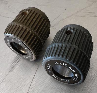
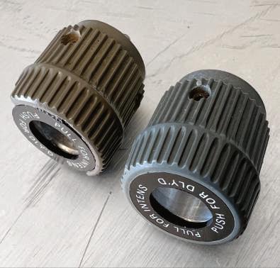
Fixing the plug-in connectors
Fixing the 515A oscilloscope
Here you'll find hints, descriptions and suggestions on miscellaneous topics related to Tektronix oscilloscopes’ repair and restoration.
If someone, like me, has something wrong in his head, he can find that restoring an old Tektronix scope can be an exciting activity. In most cases, they can be repaired because excellent documentation is available,
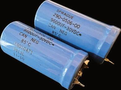
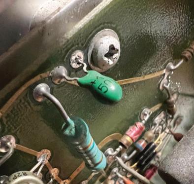
The components used were, in general, of high quality. Apart from transistor or ICs, the most common faults are caused by the large electrolytic capacitors in the power supply section, which are not short-circuited or blown, but simply lost all their capacitance. Also, the Tantalum capacitors, that in Italian are called “drop-shaped”, and the so-called “bumblebees” often require to be replaced.
For today standards, the use of sockets for almost any semiconductor devices or relays is surprising. It is even more surprising that these sockets are still reliable, if used with a minimum care. They are very useful in locating faults: if you don’t want to squeeze your brain to find the wrong transistor, just check all of them with a multimeter.
Another frequent cause of problems are the switches, but cleaning them is often enough. See page 45 for cleaning tips.
As a true pioneer should do, Tektronix also produced a lot of books to broadcast its technology to the world. Even today, many of them remain interesting and worth reading.
3 2 1


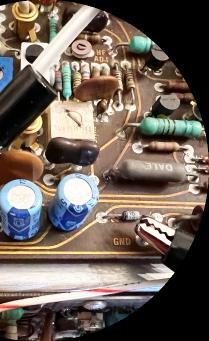
❶ These electrolytic capacitors have lost almost all their capacity and were substituted with modern ones in a 7603 oscilloscope.
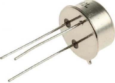
❷ One of the feared Tantalum capacitors. When they short, they can cause significant damage.
❸ One of the Tektronix books that opens up their technology to the world.
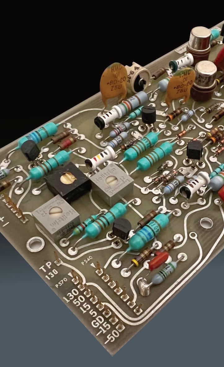
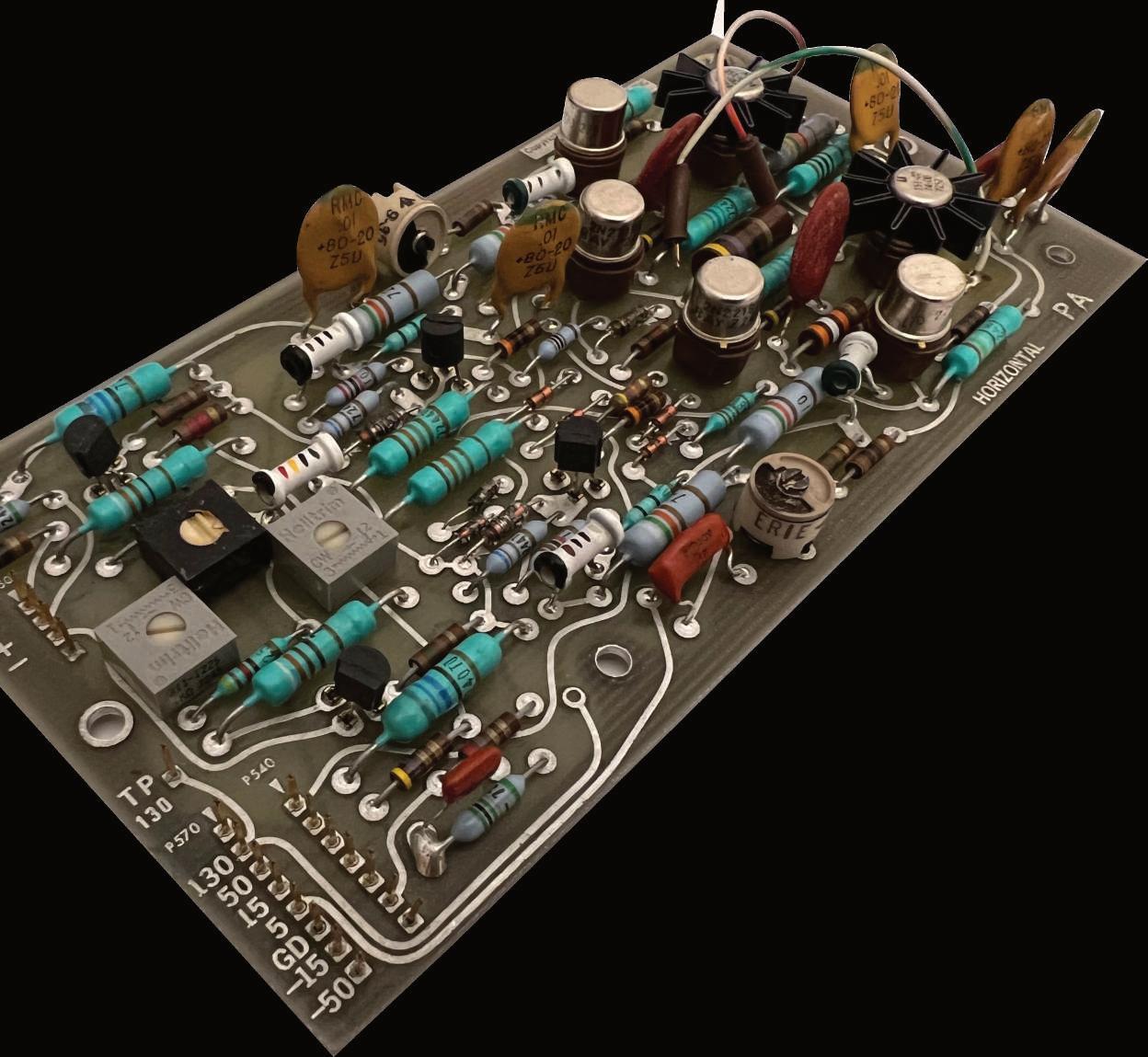
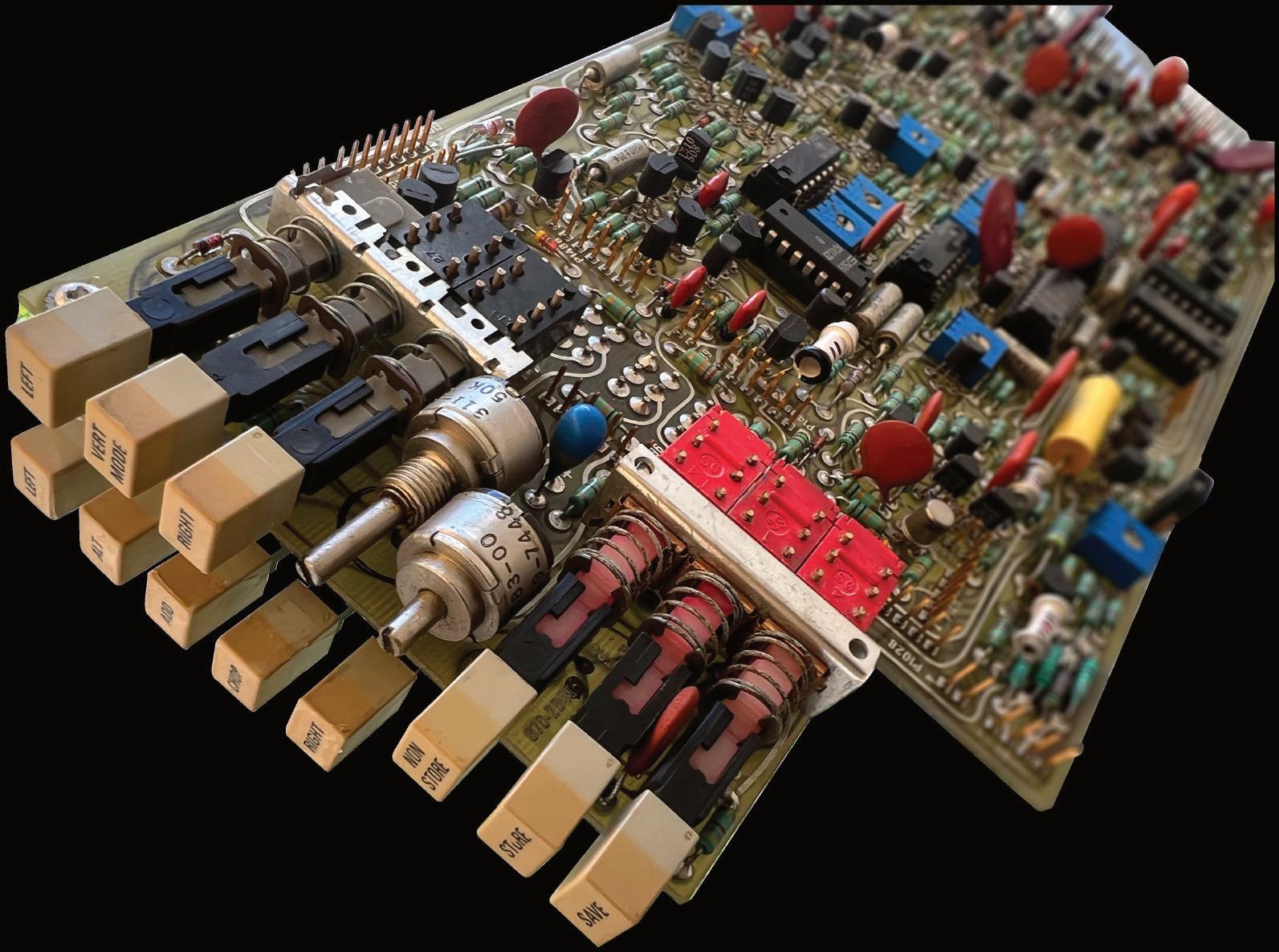
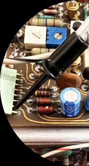
❹ A typical board of a 7000-Series oscilloscope. Note the sockets for the ICs and transistors.
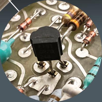
❺ The detail of an almost invisible transistor socket.
You have to know it to see it!
4 5


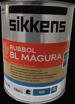
The Tektronix blue is very peculiar and does not match any RAL color. I am not even sure if that color has been always the same in all these years. My guess is that the older units were darker and the newer are lighter. My opinion is based on what I could see in the units I have, but maybe also that the color changed simply as a consequence of age.
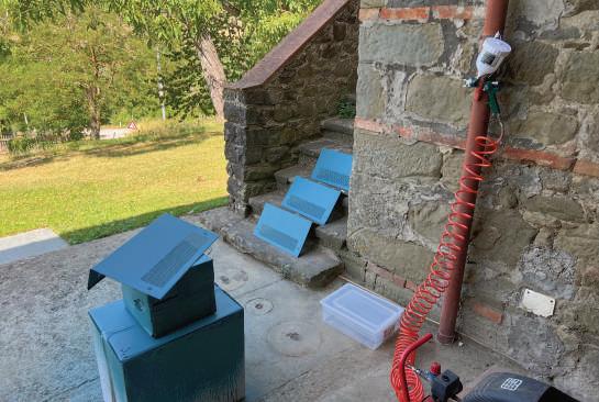
Some of my units looked so bad that I felt compelled to at least try to repaint them. What I could do was to get a cabinet in a rather good state (465), go to a shop specialized for painting, and ask them for a special color.
They were very intrigued: nobody had asked them for paint for an oscilloscope! In the end, they produced a color that was not perfect but rather close to the target I wanted. The cost was not so little (more than 50 euros for 1kg), but the painting is really good quality, much better than any spray.
Should it interest someone, the paint code is Sikkens Rubbol BL Magura Q4.20.38 5051.
In the photo on the right: the darker ones are the original ones, the lighter ones are the ones I repainted.

Here you can see the difference in color between the TIME/DIV knobs of a 7B53, one of which has obviously been used, the other one has probably spent its life in a box.
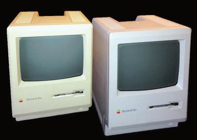
The effect of UV rays on plastics is very strong, as restorers of old computers know well (photo on the right).
In my professional life, when I had to work with plastics, I first thought it would be easy. But I learned that plastics, like electronics, require a lot of technology and experience. A plastic mold is usually large, heavy, and complex. There are many factors to consider, such as the ability of the material to flow at extreme angles, temperatures, deformations, etc. The color also plays a big role in the result.
Years ago, we introduced a new product, very important for our company. It was designed by a famous industrial designer and we developed a very rigorous testing plan, to avoid problems in the first units. One of its key points was a beautiful glass in the front, glued to the plastic with a super technological adhesive, subject to deep testing. Well: after a few days we received complaints about the glass falling apart… We suspected everything: the production process, the temperature, the humidity, etc. But in the end we discovered that the cause was… the color! All the tests had been performed with yellow plastic, while the production was in green. It was obtained with a pigment, added to the raw material, not compatible with the adhesive. Still today, while I am writing these notes, I am fighting the problem of the EN 45545-2 certification (about the safety of the railway sector) of an orange color, that is not present in the black.
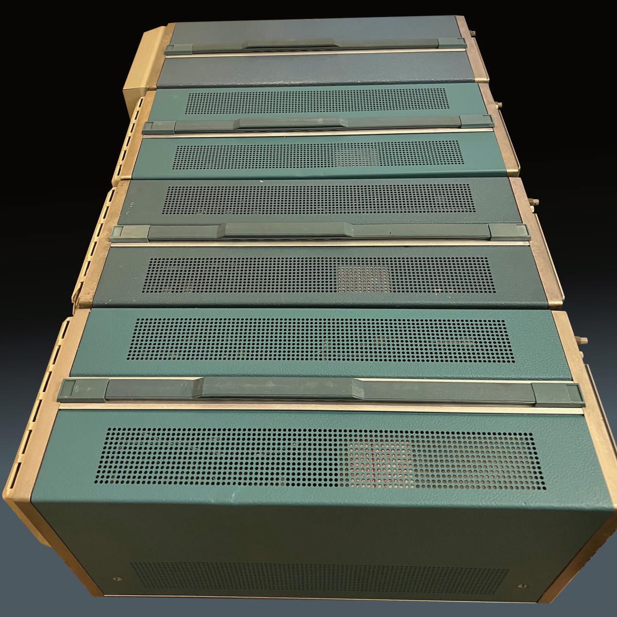
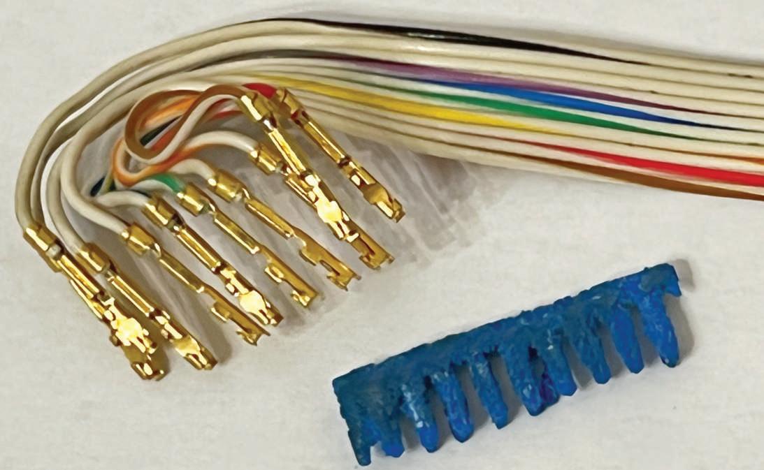
Perhaps Tektronix had a similar problem. My R7844 S/N B010112 is probably the 12th unit produced, but, as you can see from the photos, it is still in good shape. So I was surprised when I found some blue plastic debris in the box. Eventually, I found its origin: two connectors of a flat connecting the Readout board. Both connectors were almost completely corroded and crumbled, the largest piece remaining is the one in the photo here. The other connectors were all good and there was no sign of corrosive liquids. I suspect that the blue plastic pigment caused premature aging of the material (if we can say “premature” after 38 years).
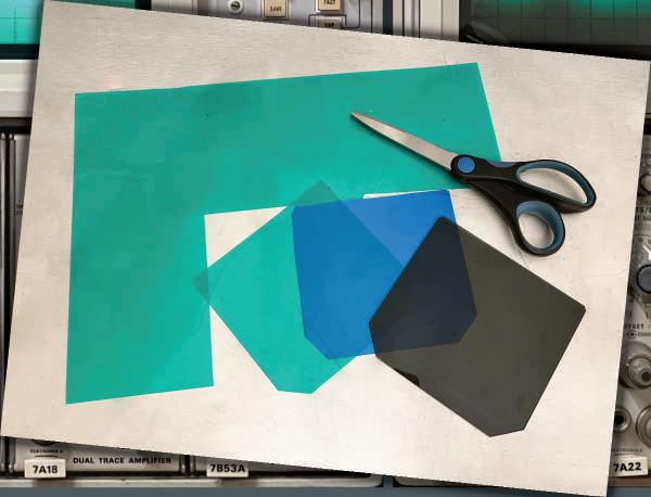
As for human beings, the “gaze” characterizes an oscilloscope, and they also use “contact lenses” to modify their look. What is the best optical filter we can use to make our work easier? I thought that it depends on the photo camera used, but I discovered that normally the colored filter was removed before taking photos at high writing speed to increase the light hitting the film (the transparent filter has the purpose of implosion protection and is not to be removed). So, it was probably only a matter of taste, and/or of environmental conditions.
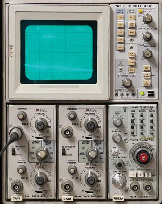
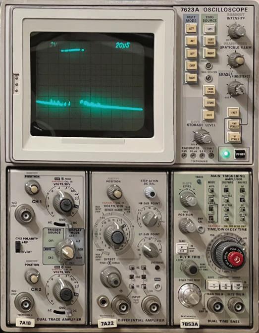
Here you can see scopes with different filters: in the 7603, while in 1 2
nal filters, in spite of the photos, are, in my opinion, much more eye-straining. The best, in my taste, is the standard blue filter ❸ of the 7854/7904 etc. In the case of my 7633, which arrived without filter, I was forced to built a new one by buying some transparent plastic sheet from Amazon. (❻). I tried with various colors and probably the best is the light green (❹), while the standard, in the 7623A on the right (❺) is again too dark and makes it harder to see the details. However, as you can see if you have to take photos with your smartphone, the worst (dark green) becomes the best… 4 5 6 3
If you are going to restore an old 7000-Series oscilloscope, you will learn soon that most of its components are of top quality, even after half a century, but some of them were, or are today, very weak. Among them, the labels on the pushbuttons. If you are not very careful, these writings dissolve like snow in the sun, even with light detergents (see the photo below on the left).
So, I find convenient to clean the buttons with a swab, using only clean water on the writings and then applying a transparent coating to protect the characters against wear and erasure (photo below on the right).
But what can we do if the labels have already been erased?
First, you need a template. that you can download ready to print from my web page. If you prefer, you can create them by yourself. I found two different fonts that are very similar to the original one: BLOGGER SANS MEDIUM or UNIVERS CONDENSED.
I used a waterslide decal paper from Hayes, bought on Amazon, which is reasonably priced. Additional details can be found on the following pages.

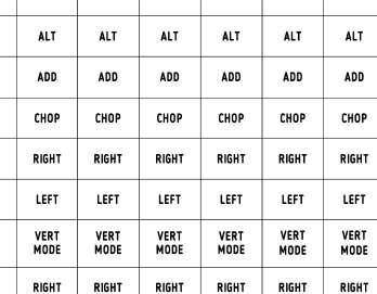
❶ The starting point is a good waterslide decal paper for your printer (laser or inkjet). I used this one from Hayes that is easy to find on Amazon.
❷ You need a template: create it yourself or use the one I prepared (which can be downloaded from the web page of this book). Print it on the special paper.
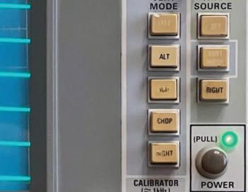
❸ This is a sample starting point. Yellowed keys and damaged labels. The yellow is from the old protective coating, not from key plastic, good indeed.
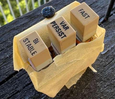
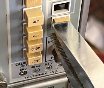
❹ Removing the keys is easy and requires only a pair of pliers. Just grab them gently and pull outwards.
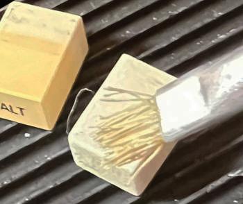
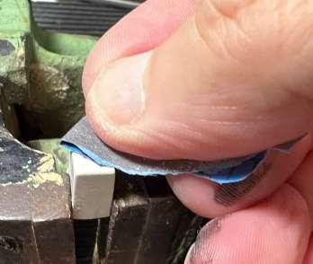
❺ Now you need to clean the keys from the old coating. I use nitro thinner, carefully and quickly because it is very aggressive to plastics.
❻ I suggest you finish by sanding with very fine sandpaper to get a perfect surface to apply the waterslide decal.
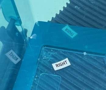
❼ Now cut the waterslide decal and put it in the water. They say 30-60 seconds, but being the decals small, few seconds are normally enough.
❽ When the decal is ready, gently help it to slide from the paper support to the key and position it correctly. It's simpler than it might seem.
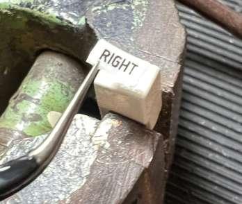
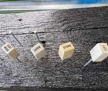
❾ When dry, apply a clear coat and allow the keys to dry. The keys can then be pushed back into place. The result is shown on the right.
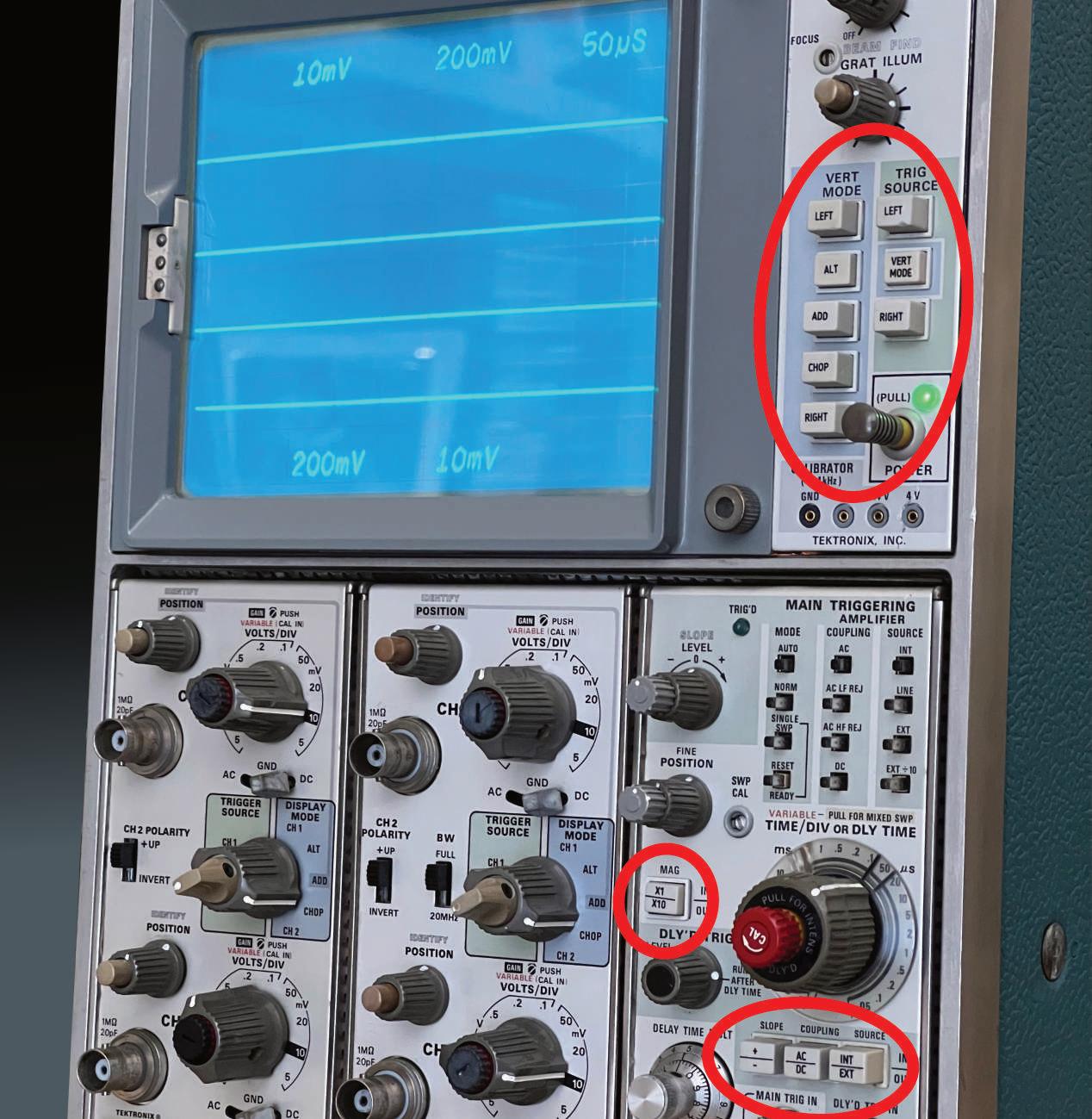

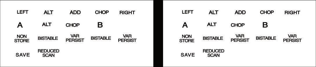
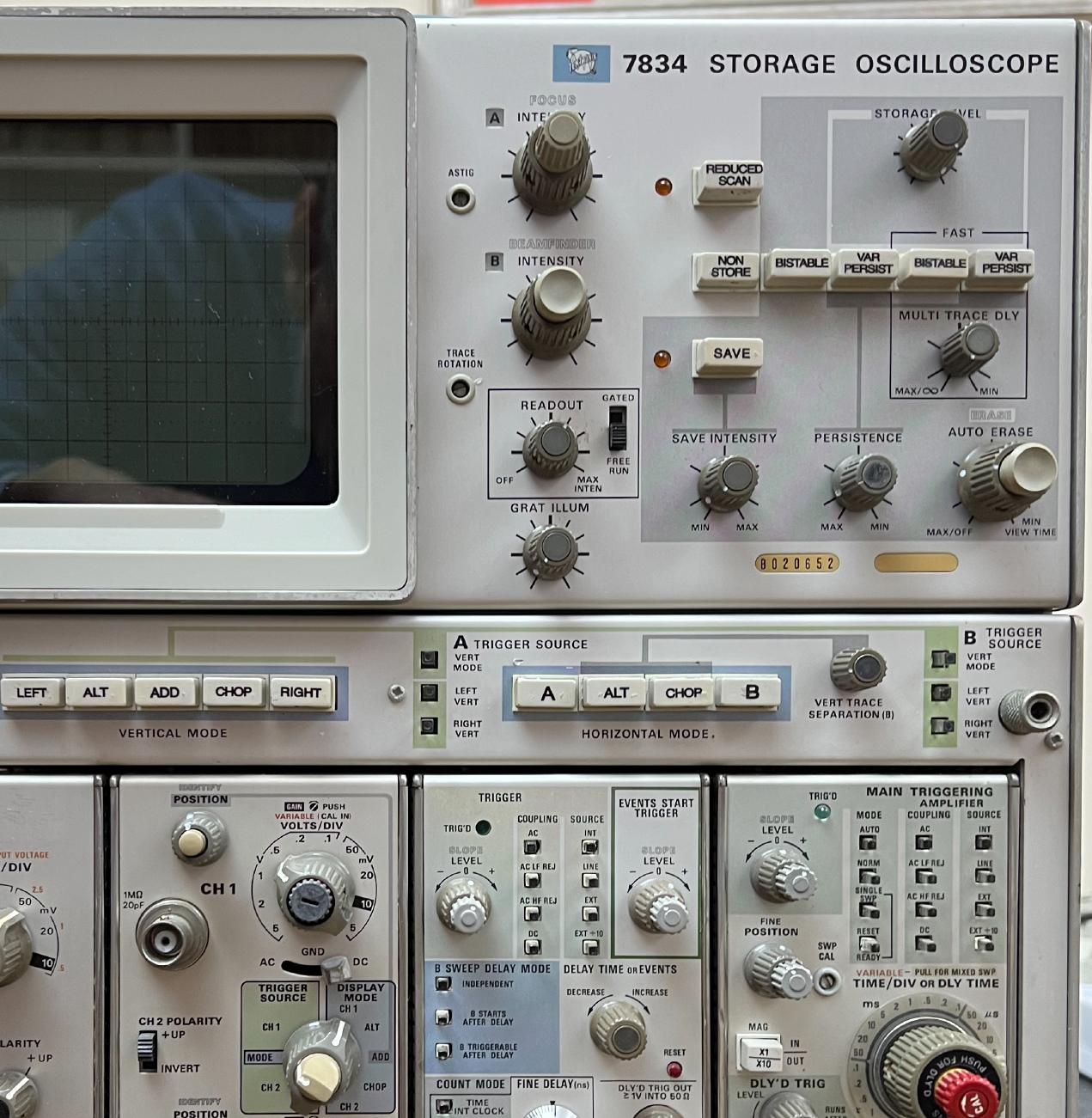
The 7834 (and likely other models) has different keys compared to the 76x3 described on the previous pages; many inscriptions have a different size, and the font is also different. So the template you can download from my web page is not suitable in this case. You can use a copy of the one reported here below; print it in 1:1 scale (100%). The keys became very yellowish, but when cleaned with solvent they return to grey. It is very aggressive, so be prudent. I was surprised that the treatment also worked for the knobs, if used wisely. Confirmed by other details, I suspect that the coating is just… nicotine. Probably the 7834 had to endure many years of secondhand smoke. In the front page, the final result of the restoration, compared to the picture below of the original condition.
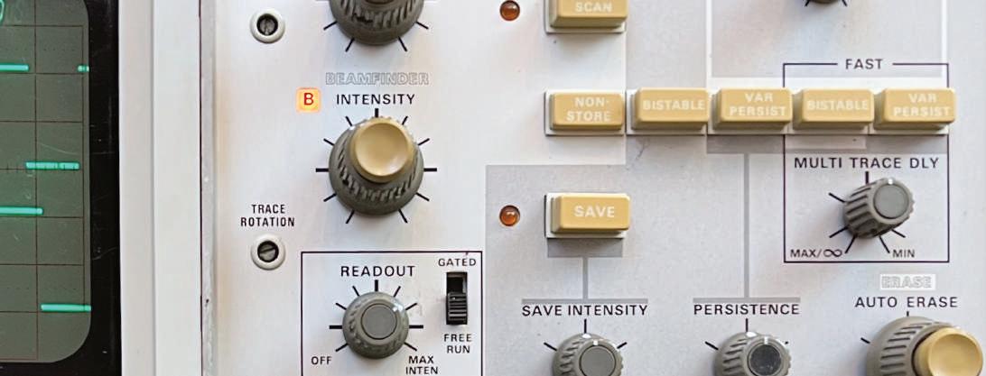
❶ These pictures can be used to be directly printed on a waterslide decal paper (use 100% enlargement factor). ❷ The keys and the knobs as they where when I purchased the 7834. ❸ The front panel with the renewed keys and cleaned knobs.

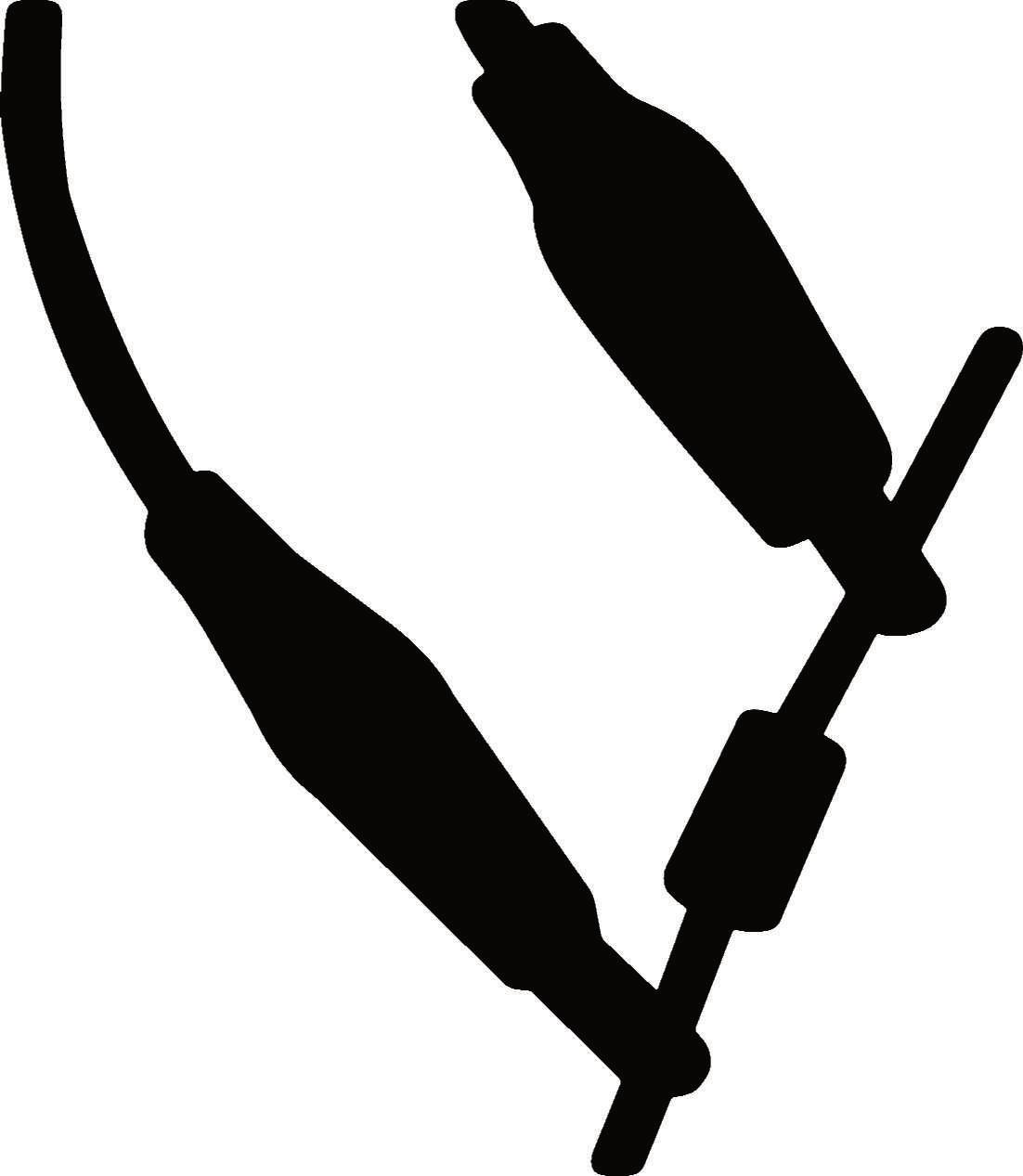
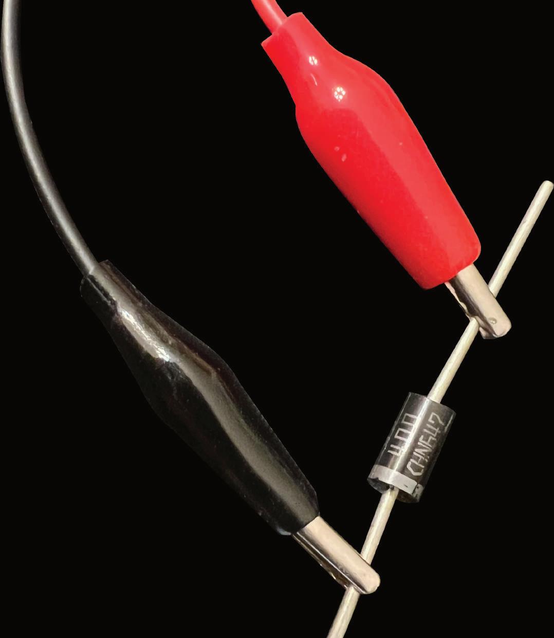
❷ TESTING A DIODE: It’s easy, just check that it does not conduct when reverse-polarized (red on cathode), and that the cut-in voltage is between 0.2 and 0.9 V when forward-polarized.
2
3

1
Most of us don’t have a curve tracer to analyze the characteristics of diodes or transistors. As I see it, the only way to check these active components is with an old-fashioned multimeter, also known as a VOM (volt/ohmmeter).
A diode (❸) is an electronic component with two terminals, called cathode and anode, that conducts only in one direction, i.e. when the anode is positive with respect to the cathode (direct or forward polarization). When the anode is negative, it does not conduct (reverse polarization). A good diode should have zero resistance in the former case and infinite in the latter. The reality is somewhat different; diodes must exceed a threshold voltage, or cut-in voltage, in the forward direction before they can conduct electricity.
Each VOM (❶) has a function to test diodes, implemented as shown in schematic ❷. You test that the diode does not conducts when reverse polarized and that conduct when reverse-polarized and that it conducts when forward-polarized. In this case the VOM gives you the cut-in value (normally 0.2÷ 0.9V). The test is done with a 3÷4 V battery.
A transistor (❻) can be seen as two diodes combined (❹ and ❺), so you should test it as two diodes. E.g (for an NPN): red probe on B, conducting to C and E. Black probe on B, no conduction toward C and E. Also, test for no conduction between C and E in both directions.
Other components soldered to the board can alter the readings. Luckily, most of the transistors on the 7000-Series boards have sockets, so checking them is extremely simplified.
NPN
In my whole life, I never tested so many transistors as now that I work on old Tek stuff…
B B E E E B C 4 5 6
Every time I read instructions to “measure the ripple,” I feel uncomfortable because I usually see a lot of noise that seems unrelated to the ripple itself. In other respects, measuring the ripple is important when we deal with power supplies, as often happens with Tektronix old stuff. I don't have a lot of experience with them, but for what I learnt in these months, power supply problems are the most common with this old gear, especially for the “dried” capacitors (I don’t know if really anything dries, but it is a convincing expression). I found more than a couple of scopes that were neither starting up, because the filter electrolytics had lost almost 100% of their capacity. But what when you are in the middle of the drying process, i.e. the capacitors are not yet dry but on their way to drying? Normally you get a greater ripple, which can cause malfunctions.
A sign of that is given by readout characters that begin to “dance”. At first, I thought it was some timing problem in the Readout board, but I was wrong: in the 7000-Series, there is no raster, like in a television; if the character positions are unstable, they move according to the changing voltage on the screen. If the ripple affects the horizontal and vertical amplifier as well, the effect is that the characters slightly move horizontally and vertically, producing that funny and hated effect. I tried to correct locally the +130V ripple on the horizontal amplifier (adding a capacitor), characters continued oscillating only vertically. But adding capacitors locally is not a good solution, we must go to the root of the problem.
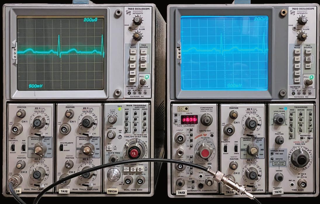
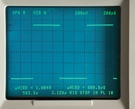
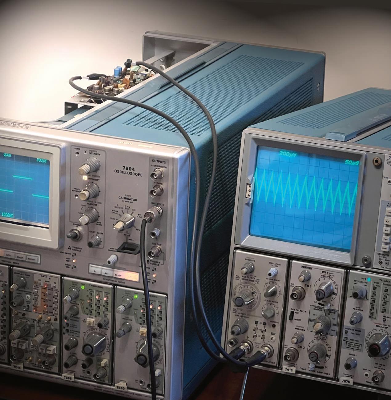
I found a Tektronix technical note specifying the allowed ripple for 7904, 7844 etc. and it is in the 1÷2 mV order. How can I measure that? The article somehow gives the answer: use a differential vertical amplifier. So I tried with the 7A22 and… wonder, it works!
Just do this: get a BNC/BNC cable, cut it exactly in the middle (to have two identical cables), and apply some form of clip at the free end, forgetting the screen. Now connect one cable at the “+” input and the other at the “–”. On the other side, connect one of them to the ground of the Device Under Test (DUT) and the other to the voltage terminal you want to check. Put both channels in AC and enjoy the neat screen. In general, it is better to limit the amplifier bandwidth with the relative knob, normally we are not interested in the high-frequency noise.
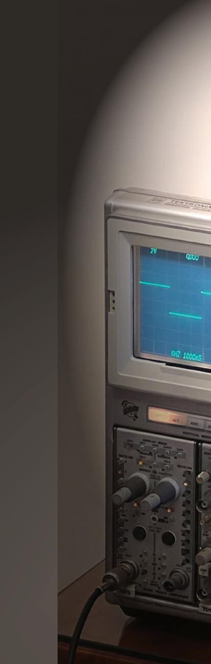
In the photo: a 7603 checks the ripple on a 7904. Look at the marvelous 200 µV in the display!
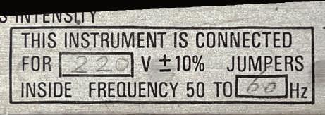
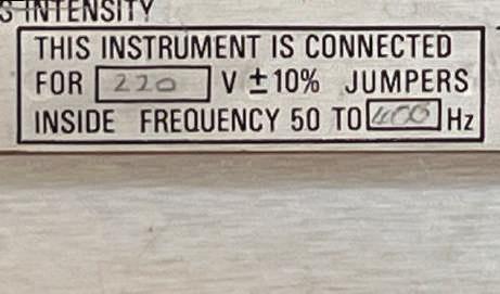
Looking at many equipment labels, I often asked myself: “Why 400Hz”. 400 Hz power networks have become the standard for weapon systems, aerospace, and aircraft industries worldwide, because the 400 Hz equipment is lightweight, reliable, and provides high power capability. As a consequence, airports, hangars, and ships that carry aircraft have 400 Hz power systems.
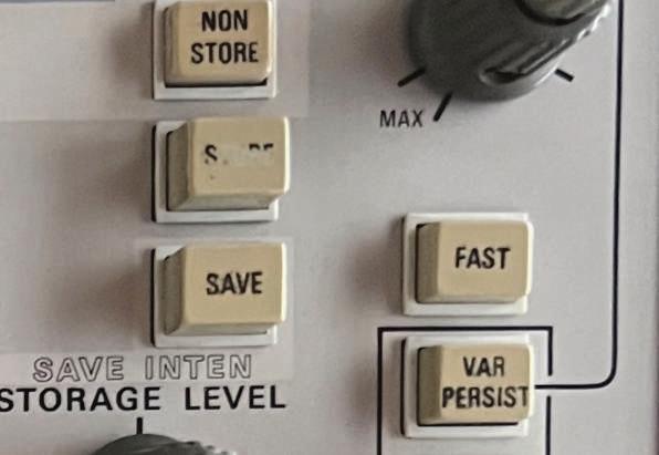
Continuing with my questions, I noticed that some 7000-series oscilloscopes have a label stating 5060Hz, while other have 50-440 Hz (photo below). Why is this, considering that their power supplies are almost identical?
The explanation is found in the 7844 oscilloscope description in Tekscope 6-1974: Because the 7844 has a DC fan it will operate from a power line having a frequency from 48 Hz to 440 Hz.
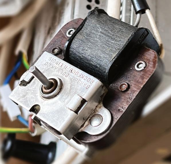
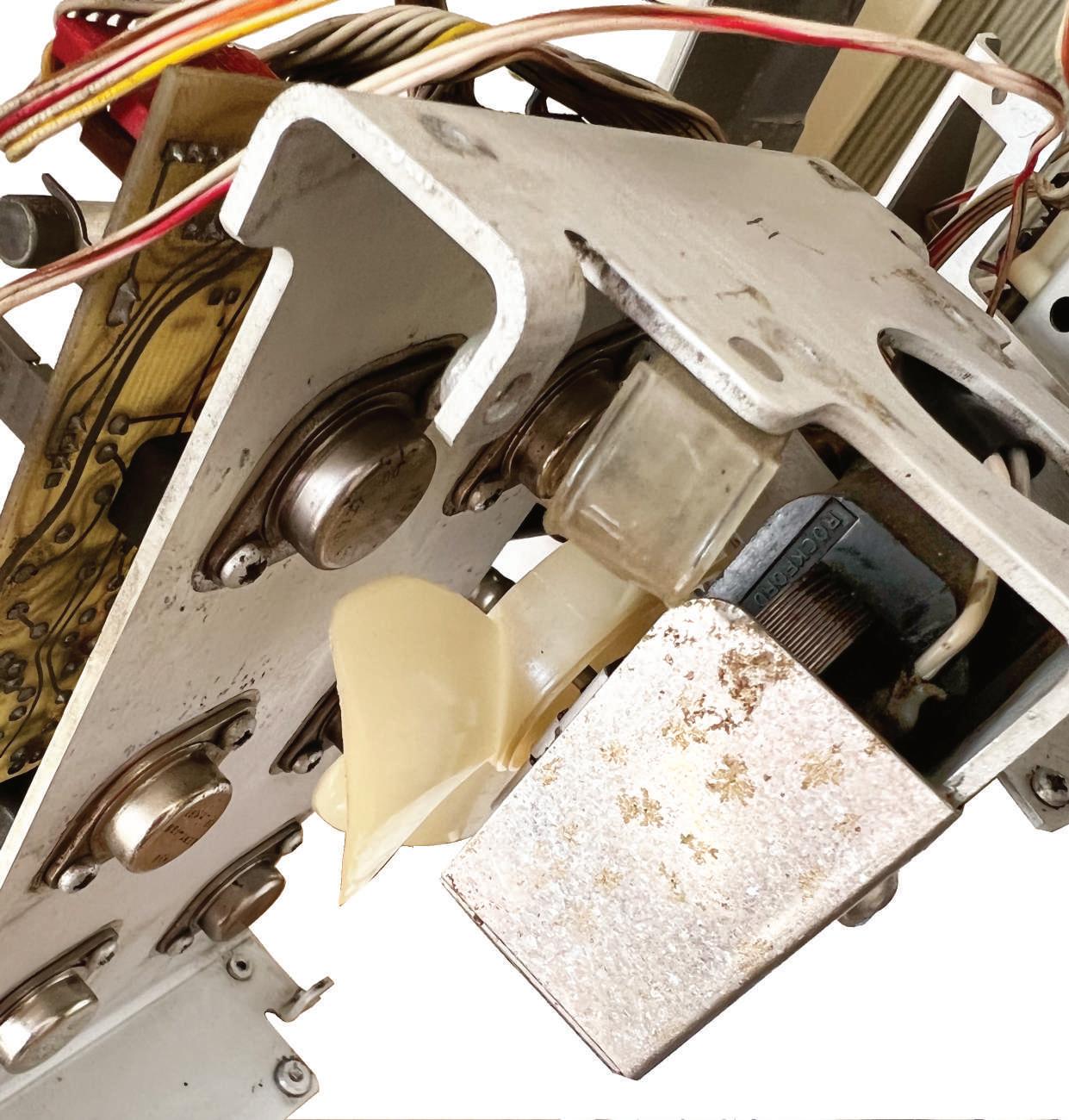
I then checked with my electronic friends: those limited to 60 Hz are the ones with the fan! The fan is the limiting factor, because often, when present, the fan is based on a synchronous motor, in which the rotation of the shaft is synchronized with the frequency of the AC supply voltage. These inexpensive and durable devices can handle 50 or 60 Hz but cannot operate at 440 Hz.
I said they were durable, and they seem to be, but the fan in my 7633 had started becoming a little noisy, so I disassembled it, as shown here. The fan’s ball bearings are sealed, and it is not possible to overhaul them. So I limited myself to cleaning everything and applying a few drops of oil. The result is good, and the noise has disappeared. Not too bad for a motor that has probably been running for decades.