
Instructions: SLIDER FOR MICRO:BIT V1A


MonkMakes
Page 2
TABLE OF CONTENTS Introduction 2 Parts MonkMakesLearningTroubleshootingMicroPythonProgramProgramProgramProgramTheGetting..........................................................................................................................3Started...........................................................................................................4VariableResistor61.SliderNumber.........................................................................................82.SliderBarGraph.....................................................................................93.Snake.....................................................................................................104.MuPlotter.............................................................................................11withMu..............................................................................................12.......................................................................................................1314.............................................................................................................15 I
The Slider for micro:bit allows you to interact with your micro:bit by sliding a control left and right. The board uses a 10kΩ linear variable resistor (pot) to output a voltage between 0 and 3V that can be measured in your micro:bit programs using one of the micro:bit connections as an analog input.
NTRODUCTION
Set of
Page 3
Slider for micro:bit alligator clip leads leads)
(5
PARTS Please note that a BBC micro:bit is NOT included in this kit. Before you do anything else, check that your kit includes the following items:


About Alligator Clips
Page 4
GETTING STARTED
When using the alligator clips to connect your micro:bit to the MonkMakes Slider for micro:bit board, you have to be a bit careful how you connect the clips at the micro:bit end. The best way is to connect the clips vertically as shown below. Connecting the alligator clips like this prevents any accidental connections between the large connectors with the holes in and the much smaller connectors (gold lines in the photo above)

Connect the micro:bit to the Slider for micro:bit
Page 5
idea to use the red lead for 3V, black for GND and a different color to connect the output of the Slider for micro:bit to your BBC micro:bit. You can use P0, P1 or P2 of your micro:bit, but for the example programs here, it is assumed that you have connected it to P2 as shown above.
Use three of the alligator clip leads to connect your micro:bit and Slider for micro:bit
Itstogether.agood

The main component of the Slider for micro:bit is a sliding variable resistor (also often called a potentiometer or just pot). The other components on the board are designed to protect your micro:bit against accidental damage should you connect things the wrong way around and the amber power LED that show that the Slider for micro:bit is powered.
Here's the schematic diagram of a variable resistor and micro:bit working together. The variable resistor is actually a resistive track, across which the micro:bit supplies a voltage of 0V at one end (the left) and 3V at the other (right). When you move the slider left and right you are moving a sliding electrical contact along the track. When the slider is at its leftmost position, the voltage at the slider will have a voltage of 0V and when its at the rightmost position the slider will have a voltage of 3V. When its in the middle position, this voltage will be half way between 0 and 3V in other words 1.5V. Note that the actual voltage will probably be less than 3V if you are powering the micro:bit from batteries. The slider voltage is measured by the micro:bit using P2 (or whichever pin you decide to use) as an analog input.
THE VARIABLE RESISTOR
The three connections 0, 1 and 2 can all be used as analog inputs. In Blockcode, you do this using the analog read pin block. This block measures the voltage at the connector specified but rather than return the actual voltage in Volts, it returns a number between 0 and 1023. When the slider is in its leftmost position, the reading will be 0 and when rightmost Page 6

the reading will be 1023. Note that in practice the maximum value will be around 1013 rather than 1024 because of extra circuitry built into the Slider for micro:bit that protects the micro:bit.
the same as the blocks code above. You can download all the Python example code for this kit at https://github.com/monkmakes/mb_slider.
The program is called analog_reading.py from microbit import * whileifTrue:button_a.was_pressed():display.scroll(pin2.read_analog())
This example will display the reading when button A is pressed. Load it onto your micro:bit (see the link) and try moving the slider to various positions and then press button A and see what the reading is.
For more information on using MicroPython on your micro:bit, see the Section MicroPython with Mu, later in these instructions. Here are some more programs for you to test out the slider.
Page 7
Click on this link and then Download the program onto your micro:bit: Ifhttps://makecode.microbit.org/_5x9RyqRKyTwLyouareusingPython,thefollowingprogramdoes

This program displays a single digit between 0 and 9 depending on the position of the slider. To try it out using Blockcode, visit this webpage in your browser.
PROGRAM 1. SLIDER NUMBER
Clickhttps://makecode.microbit.org/_C9mFbkMwu7iwonthe
Download link at the bottom of the window and copy the HEX file onto your micro:bit. Once flashing is complete, you should see that the micro:bit's display shows a number. When you slide the Slider back and forth you should see the number change from 0 (left) to 9 (right). By dividing the analog reading by 110, the maximum reading of 1023 becomes 9 (actually 9.3) but we use the round block to round this down to 9. Here is the MicroPython version of this program. The program is called slider_number.py. from microbit import * while True: x = int(pin2.read_analog() / 110) display.show(x)
Page 8

This example uses the Blockcode plot bar graph of block to display a bar graph that responds to the slider position. Here's a link for the code: https://makecode.microbit.org/_HYtds3Yg9J32
Page 9
PROGRAM 2. SLIDER BAR GRAPH
Notice how the range of the plot bar graph of block is set to 0 to 1023. Move the slider about to change the display. The Python version of this is a little different because MicroPython for the micro:bit does not include an equivalent of the plot bar graph of block and so we have to write our own. This is contained in the bargraph function that expects a number between 0 and 5 as its parameter and then displays 0 to 5 lines of LEDs. You will find the code in slider_bar_graph.py from microbit import * def fordisplay.clear()bargraph(a):yinrange(0, 5): if a > fory:x in range(0, display.set_pixel(x,5): 4-y, 9) whileslider_posnTrue: = int(pin2.read_analog() / 200) bargraph(slider_posn)

y2,
Thehttps://makecode.microbit.org/_hgvDyoM2KVEPcodeusesanarraytokeeptrackofthedotposition on each row. The forever block first shuffles all the dot positions up one place using a for loop. It then clears the display and then sets the position of the bottom most dot to be determined by the slider position. It then draws all the dots. The pause block just slow things down. Here is the MicroPython code which follows exactly the same pattern. You will find it in the file slider_snake.py from microbit import * import positionstime= [2, 2, 2, 2, 2] def forscroll_up():yinrange(4):positions[y]= positions[y + 1] whilepositions[4]scroll_up()display.clear()True:=int(pin2.read_analog() / 240) for y2 in display.set_pixel(positions[y2],range(5): 9) time.sleep(0.1)
PROGRAM 3. SNAKE
This example uses the Slider to make a wiggly snake animation when you move the slider. This is a little difficult to describe, so perhaps just try it out:
Page 10

The data has to be sent as a Python tuple, even though it only has one value. That's why there are extra () and a comma in the line highlighted above.
This final program is only available for MicroPython using Mu because it uses Mu's Plotter facility to plot values sent out from the micro:bit to your computer over USB. Load the program onto your micro:bit (called mu_plotter.py) and then click on the Plotter button in the tool bar. Now when you move the slider about you will see the values change in the plot. Here's the code: from microbit import * import time while True: data = (pin2.read_analog(),) time.sleep(0.05)print(data)
PROGRAM 4. MU PLOTTER
Page 11

Clickhttps://github.com/monkmakes/mb_slideronthegreen
The code for this kit is available both as Block code and as MicroPython. If you would like to run the MicroPython versions of the programs rather than the Block code, then you can download all the programs from Github here:
MICROPYTHON WITH MU
Code button and select the option Download ZIP. Extract the ZIP archive and you will find a directory containing the python programs for all the Youprojects.can then use the Mu editor (https://codewith.mu/) to Load the downloaded programs and then Flash them onto your micro:bit. The MicroPython versions of the programs are modelled closely on their Block equivalents and should be easy to follow. Page 12

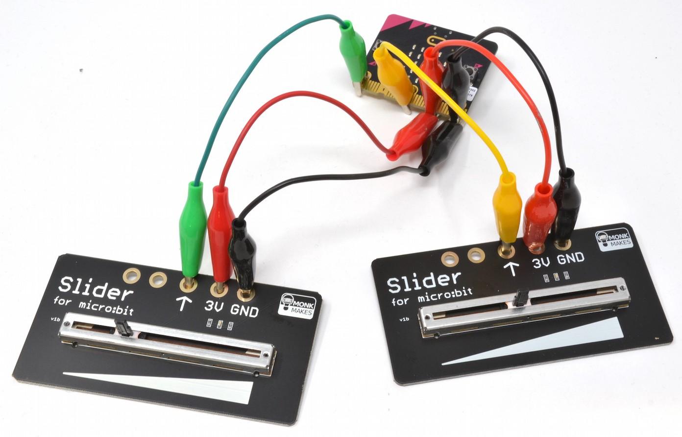
Solution: You can use any of the micro:bit's pins to read analog values, so to use a second micro:bit you just need to supply it with power and connect its output to an otherwise unused pin as shown below. Note that you will need some more alligator leads.
TROUBLESHOOTING
Solution: Make sure that your micro:bit itself is receiving power and that the GND and 3V connections of the micro:bit are connected to the GND and 3V connectors of the Slider.
Problem: How can I connect more than one Slider for micro:bit to my micro:bit?
Problem: I am moving the slider, but the reading is not changing.
Page 13
Solution: Make sure that the analog read pin block has the same pin selected as is physically connected to the Slider for micro:bit's output.
Problem: The amber power LED on the Slider for micro:bit is not lit.
LEARNING
Page 14
If you want to learn more about programming the micro:bit in MicroPython, then you should consider buying Simon Monk's book 'Programming micro:bit: Getting Started with MicroPython', which is available from all major book sellers. For some interesting project ideas, you might also like micro:bit for the Mad Scientist from NoStarch Press. You can find out more about books by Simon Monk (the designer of this kit) at: http://simonmonk.org or follow him on Twitter where he is @simonmonk2
micro:bit Programming

From left to right: Electronics Starter Kit for micro:bit, Power for micro:bit (AC adapter not included) and 7 Segment for micro:bit. Page 15
all sorts of kits and gadgets to help with your maker projects. Find out more, as well as where to buy here: https://monkmakes.com you can also follow MonkMakes on Twitter @monkmakes.
MONKMAKES
For more information on this kit, the product's home page is here: Ashttps://monkmakes.com/mb_sliderwellasthiskit,MonkMakesmakes


