LOW VOLTAGE HRC FUSE-LINKS & HOLDERS

HIGH RUPTURING CAPACITY (HRC) FUSE-LINKS
WHAT IS AN HRC FUSE?
A HRC fuse is a device that protects an electrical installation against the dangerous consequences of excessive over-current by breaking / interrupting the current in a controlled and predictable way. They have been around for more than 100 years now and have become one of the key methods of maintaining electrical safety.

A full range HRC fuse will protect against both overload faults and short circuit faults, by critical design of the internal element. HRC stands for High Rupture Capacity. This means the fuses are capable of withstanding massively high short circuit fault current, values of 80kA and 120kA are common. In doing so, the arc must be extinguished, and the body of the fuse must remain intact to ensure there is no risk of energy escaping from the fuse and causing damage to equipment or harm to personnel.
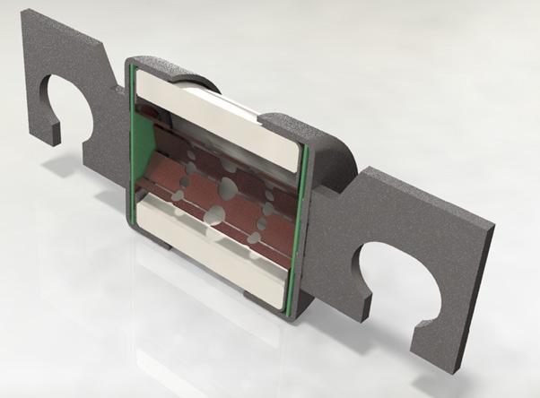
Fuses are based on a simple construction but the technology behind the design is complex, involving electrical circuits, electromagnetics, heat transfer, material science, mechanical engineering and plasma physics.The fuse-link is the component that actually breaks the current, a fuse may consist of several components – namely a fuse-link, a fuse-holder, fuse carrier and a fuse base.
FUSE-LINKS ARE USED FOR THE PROTECTION OF THE FOLLOWING SYSTEMS
Fuse-links are categorized by breaking capacity and utilization category under a two-letter code. The first letter indicates the breaking range.

• ‘g’ is a fuse link with full range breaking capacity from its conventional fusing current to its rated breaking capacity.
The second letter indicates the specific application requirements.
• ‘a’ is a fuse-link with partial range breaking capacity from approximately 5 times its current rating to its rated breaking capacity. Partial range fuses are designed for short circuit protection only and an associated device must be used to provide overload protection.
Some examples of these are:
• “gG” - General purpose fuse-links: Industrial equipment, electricity supply. Example referenced standards are IEC 60269-1, IEC 60269-2, IEC 60269-3,
• “gM” - Fuse-links for protection of electrical motors from high inrush current during start up. IEC 60269-1, IEC 60269-2, IEC 60269-3
• “gR” – Full range fuse-links for protection of semiconductor devices, such as semiconductor diodes, thyristors, capacitor banks. These fuse-links, also known as Fast Acting, are optimized to give lower I²t (let through energy) fuse-links. Reference standard IEC 60269-4.
• “aR” – Partial range fuse-links for protection of semiconductors, they are designed to only operate for short circuit faults. Reference standard IEC 60269-4
• “gS” - Fuse-links for protection of semiconductor devices, thyristors, capacitor banks. These fuse links are also known Fast Acting but not as fast as gR. They are designed to be optimized for low power dissipation. Reference standard IEC 60269-4
• “gPV” - Fuse links for protection of photovoltaic installations and equipment, solar power systems. Reference standard, IEC 60269-6
• “gBat” – Fuse links for protection of electric vehicle batteries and EV charging systems. Reference standards IEC 60269-7
IMPORTANT COMPONENTS WITHIN HRC FUSE-LINKS
ELEMENT
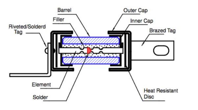
The element is the key part of the fuse design. This is the part by which the fuse dimensions are set so the design will comply with the requirements of the time current characteristics, temperature rise and power dissipation. Design and manufacture of the fuse element must be very precise and is tightly controlled.

CERAMIC BARREL
The body of a fuse-link is generally some form of ceramic due to the requirement for it to be a good insulator and to be able to withstand massive amounts of electrical energy and thermal stress generated by a short circuit failure and overload currents. Part of the pass/fail criteria of a fuse test is to ensure the body of the fuse does not crack under maximum energy conditions.
MATERIAL OF END CAPS AND TAGS
End caps are used to mechanically connect the element within the fuse body. There are many options of tags to ensure the end user has the best option for their application. The cap and tag material is designed to be highly conductive to provide low temperature rise and low power dissipation so the material is generally copper or brass and is often tin or nickel plated and sometime even silver plated to ensure the optimum characteristics are met.

FILLER / ARC QUENCHING MATERIAL
To ensure that the arc generated by an electrical failure is quenched as efficiently as possible within the fuse, the filler used is silica sand. The sand plays an integral part of the correct operation of an HRC fuse-link.


