7 minute read
Structure
from Design Studio 3.1
by Faith Muir
Structures
Gallery Space Movable Frame Design
Advertisement
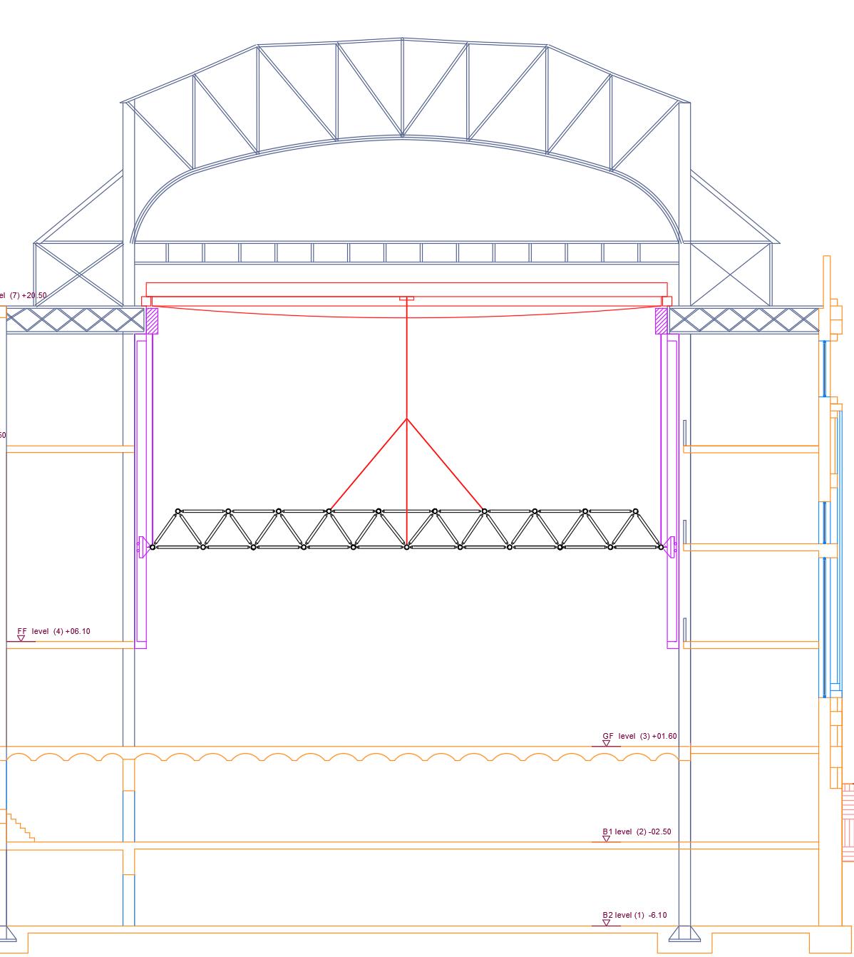
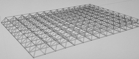
The objective is to fully utilise last remaining gantry crane of the IRT Powerhouse. The crane will be fully operational and will be the primary point for raising and lowering the new space frame roof to create a dynamic exhibition space. We are using a space frame with mild steel circular hollow section members, and galvanised steel cables (a).
(c)
(d)
(e)
(f) (g)
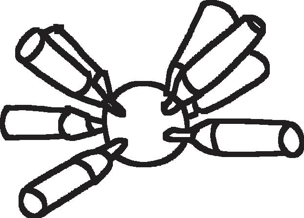
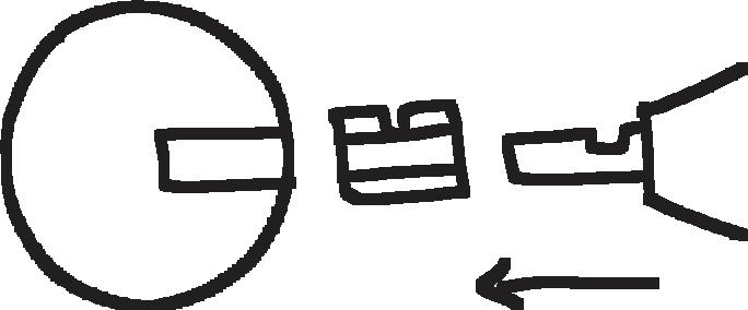
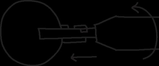
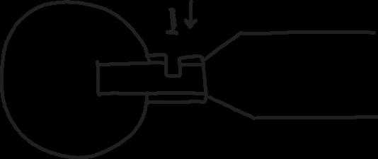
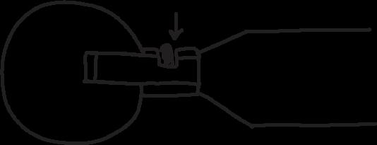
Threaded connections : The CHS members thread onto the nodes with bolts, which are then secured with dowels rather than the nuts used in a normal bolted connection (c,d,e,f,g).
The connections are prefabricated and it's only after that members are bolted in situ.
The frame is restrained laterally on rollers in bracket channels connected on to the existing columns, while secondary cables are connected to existing crane roller girders (h,i).
The structure is statically inderminate, however redundancy increases the safety of the frame. The suspension on cables removes any requirement for temporary cranes, which would be required if the frame rested upon columns.
We have decided to use a space frame as they are lightweight, easy to assemble and offer a large number points to suspend services or equipment such as lighting from, which increases the flexibility of the space.


Treating as an equivalent beam in section :

(h)
Cable support locations
Piazza and Gallery Bridges Design
These bridges divide the large interior space into smaller, and thus more manageable, spaces.
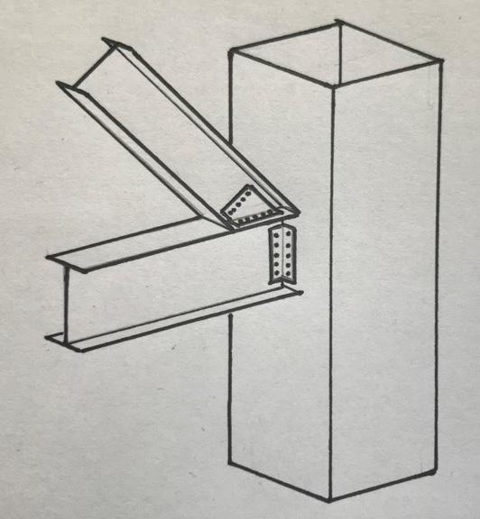
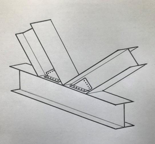
Structurally they are entirely connected to the existing steelwork frame (a,b). The truss members will connect directly into the existing columns through expansion bolts (c).
The structures are completely independent of the turbine hall ground floor. This promotes pedestrian circulation between spaces and avoids excessive loading and difficult connections into the concrete slab.
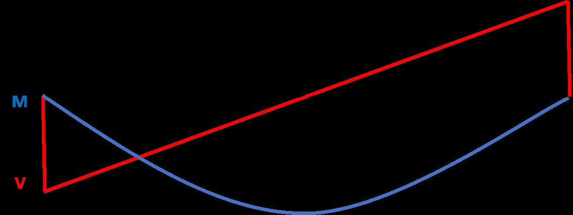
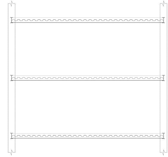
The truss is made from universal beams with a timber-finished composite floor (d), while the floor spans between secondary universal beams (e).
All connections within the truss will be bolted and considered pinned.
The trusses are to be assembled and erected using the existing on-site gantry crane.
(a) (d)
(b)


(c)
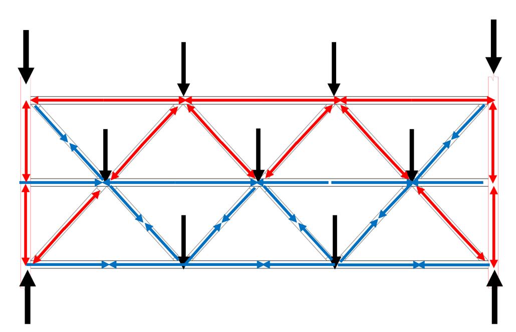
(f) Forces acting within the structure
140
88
406
90
Welded End Plate
178 Mild steel Universal Beam Maple Cross Laminated Timber Connecting Dowels
219,97
Indicative Services
500 80
192,33
0.7mm Profiled Steel Sheeting
Existing Column Ceiling Plasterboard
(g) 1:5 Detailed Section of the bridge junction
Piazza Space Cantilever Stairs Design
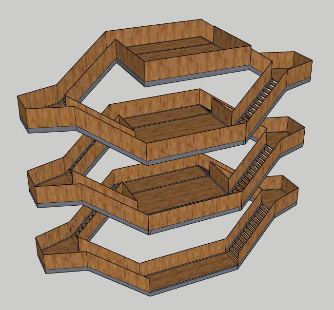
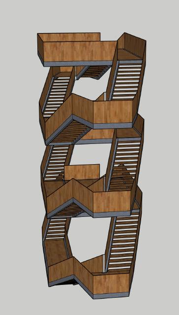
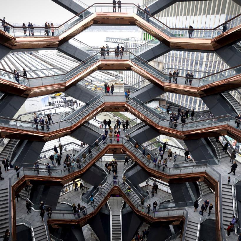
We wanted to make the stairs a focal point of the piazza area. Our group took inspiration for the stair from the Hudson Vessel, which was designer by British designer Thomas Heatherwick (a). We wanted to express the idea that the mode of travelling between floors of a structure does not need to be a structural afterthought, but instead can be a focal point that brings character to a space.
The structure itself is cantilevered from the existing mezzanine girders by steel I beams at each centre landing. The stair stringers are made from rectangular hollow sections (RHS), to give a more pleasing aesthetic appearance. The landing floors and treads are to be made from hard maple timber, as this material is a very durable timber that can be locally sourced and is therefore very sustainable (b,c).
(b)
(c)
(d)

(f)
(d) Elevation from accross the piazza
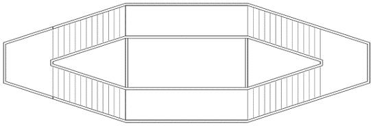
(e) Plan view
(e)
(f) Side elevation of structure
Internal Stresses
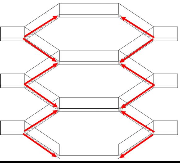
The stairs are cantilevered off the landings, which are in turn cantilevered off the existing structure. There are significant moments incurred from both dead loads and live loads at the landings half way between each floor.
Due to the eccentric shape of the stairs there will also be high torsional forces, another reason that we are proposing hollow section members.
This design is not an efficient use of material, however we believe the aesthetic intent of the stairways justify this, as additional connections would disrupt the intended appearance of the space. 34 Connections
A B C
A
B
C
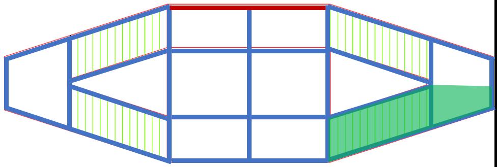
Due to their size the landings will be transported as separate beams and assembled in situ. Each stair section will be pre-welded in factory conditions and transported as one element.
Loadpaths
Load is transferred from the stair treads into the stringer girders, which are secured by bolted moment connections to the edge girders on each landing. Each flight of stairs will transfer load to the connected main landing, as this is the shorter loadpath. This load is then transferred from the landings to existing mezzanine girders through bolted moment connections. These beams then transfer the load to the closest existing columns on each side of the stairs (g,h).
(g)
(i) 1:100 Detailed Section of the bridge junction
REFERENCES 1. Aquaponics : “Aquaponics.” Wikipedia, Wikimedia Foundation, 15 Oct. 2020, en.wikipedia.org/wiki/Aquaponics. 2. Aquaponics : Angela. Aquaponics Cycle Diagram, Blogger, 28 Aug. 2019, aquaponictrend.blogspot.com/2018/10/ aquaponics-cycle-diagram.html. 3. Beam Sizes : Steel for Life, 2020. Buckling resistance moment with S275 [Online]. Available from: https://www. steelforlifebluebook.co.uk/ub/ec3-ukna/buckling-resistance-s275/ [Accessed 29 October] 4. Aquaponics : “How To Determine Feeding Rate in An Aquaponic System”. The Aquaponic Source. Available from : https://www.theaquaponicsource.com/determine-feeding-rate-in-an-aquaponic-system/ [Accessed 20 October 2020] 5. Aquaculture : “Review of life cycle assessment research on products derived from fisheries and aquaculture: A report for Seafish as part of the collective action to address greenhouse gas emissions in seafood.”. Parker, Robert. 2012.
Available from : https://www.seafish.org/document/?id=f8aff742-6d74-4aaa-bd2b-4deddbe48724 [Accessed 19
October 2020] 6. Carbon emission ETFE : University of Melbourne, 2019. Environmental Performance in Construction [Online]. Available from: https://melbourne.figshare.com/articles/EPiC_database_-_Ethylene_tetrafluoroethylene_ETFE_/9979754/1 [Accessed 19 October 2020] 7. Carbon emission values : Circular Ecology, 2019. Inventory of Carbon & Energy [Online]. Available from: https:// circularecology.com/embodied-carbon-footprint-database.html [Accessed 19 October 2020] 8. Carbon Footprint : “Comparative economic performance and carbon footprint of two farming models for producing
Atlantic salmon (Salmo salar): Land-based closed containment system in freshwater and open net pen in seawater”. Liu,
Rosten, Henriksen, Hognes, Summerfelt, Vinci, 2016. Available from : https://www.sciencedirect.com/science/article/ pii/S0144860916300036 [Accessed 21 October 2020] 9. Environmental impact : Environmental impacts of vegetables consumption in the UK. Frankowska, Jeswani, Azapagic, 2019. Available from : https://www.sciencedirect.com/science/article/pii/S0048969719319758 [Accessed 16 October 2020] 10.Expansion Bolts : Ancon, 2020. Expansion bolts [Online]. Available from: https://www.ancon.co.uk/products/channelbolt-fixings/expansion-bolts [Accessed 29 October] 11.Fin Connections : SteelConstruction.info. Simple connections [Online]. Available from: https://www.steelconstruction. info/Simple_connections [Accessed 29 October] 12.Food production : “Estimating food production in an urban landscape”. Grafius, Edmondson, Norton, Clark, 2020.
Available from : https://www.ncbi.nlm.nih.gov/pmc/articles/PMC7083843/#MOESM1 [Accessed 17 October 2020]
ETFE : Capezzuto, D., 2016. Breaking the glass roof: building with ETFE architecture [Online]. Available from: https:// www.constructionspecifier.com/breaking-the-glass-roof-building-with-etfe-architecture/ [Accessed 29 October 2020] 13.Hydroponics : “Pros and Cons of Hydroponics.” EasyPonic, 26 Apr. 2016, easyponic.com/pros-and-conshydroponics/#:~:text=Water can be reused, so,environment (and you save . 14.MVHR : Green Building Store, 2020. What is MVHR heat recovery ventilation? [Online]. Available from: https://www. greenbuildingstore.co.uk/information-hub/heat-recovery-ventilation-mvhr/ [Accessed 29 October 2020] 15.The Aquaponic Source, 2020. How to Determine Feeding Rate in Aquaponic Systems [Online]. Available from: https:// www.theaquaponicsource.com/determine-feeding-rate-in-an-aquaponic-system/ [Accessed 17 October 2020] 16.The Vessel Building : Ryan Ng., 2019 Hudson Yards Plaza - March 2019 [Online]. Available from: https://en.wikipedia. org/wiki/Vessel_(structure) [Accessed 29 October 2019] 17.Timber Composite Flooring : ArcelorMittal, 2019. Composite floor decking [Online]. Available from: https:// constructalia.arcelormittal.com/files/AMC_floors_guide_EN_June2019_LR--b47b21285b39514432cf4da5d75b23f1.PDF [Accessed 23 October 2020] 18.Urban Green Farms, 2019. Optimum Range of Temperature for Aquaponics? [Online]. Available from: https://www. urbangreenfarms.com.au/post/2019/09/15/optimum-range-of-temperature-for-aquaponics [Accessed 18 October 2020 19.Vegetable Energy Requirements : Comparison of Land, Water, and Energy Requirements of Lettuce Grown Using
Hydroponic vs. Conventional Agricultural Methods. Barbosa, Gadelha, Kublik, Proctor, Reichelm, Weissinger,
Wohlleb, Halden, 2015. Available from : https://www.ncbi.nlm.nih.gov/pmc/articles/PMC4483736/#:~:text=In% 20comparison%2C%20conventional%20production%20yielded,compared%20to%20conventionally%20 produced%20lettuce. [Accessed 17 October 2020] 36
AlexAnder P


liliAnA P FAith M


rees M rhys P
