6 minute read
RES Technical Corner by Joshua Doores, Colliers Engineering & Design


RES - Technical Corner
by Joshua Doores, Electrical Engineer, Colliers Engineering & Design
For the article this month we will consider X/R ratios and their relationship to 3 phase fault current and line to ground fault current. This article will try to answer the following questions: What is X/R?, Why does it matter?, and How is it used by electrical engineers and designers?, particularly as it relates to fault current.
We remember from ohms law, that current is a function of voltage divided by impedance, I=V/Z. Impedance is the combination of resistance “R” and reactance “X”. This ratio of an electrical systems reactance over its resistance is known as the X/R ratio. Note, that the electrical system in question could be as small as a branch circuit or as large as the entire electrical distribution for a building, including the utility.
Reactance depends on the inductance and frequency of the system. In real-life applications in the USA, we deal primarily with 60Hz voltage and current; it is a constant, therefore reactance varies based on the inductance of the electrical system. Inductance reflects how difficult it is to change the current. Coils of wire are a common electrical component that generates inductance. Voltage leads current in inductive electrical circuits.
Resistance is the measure of how hard it is for current to flow, having to do with the physical properties and circular area of the conductor being used.
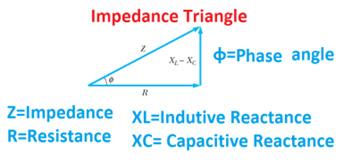
You may be familiar with the concept of the impedance triangle which is used to visually demonstrate the components that make up impedance and the phase angle between them. See figure below. As you can see, the larger the inductive reactance the larger the phase angle and the more voltage leads current, and the two waveforms become more out of phase.

Figure 1: Impedance Triangle
source: website: https://www.electrical4u.net/ electrical-basic/impedance-reactance-impedance-triangle
In summary the X/R ratio provides information on how much of the impedance of current in your electrical system is due to inductance (ie: wire coils found primarily in transformers, motors, and generators)
This matters to us for a couple of reasons. X/R ratio has a direct relationship to power factor, which is essentially how efficient we are with the power we are getting from the utility. Referring back to the impedance triangle, the larger reactance is, the larger the phase angle, the further the voltage curve shifts from the current curve and therefore the less wattage is extracted as usable power. Remember the equation P(Watts) = V*I*cos(φ). Cos(φ) is the power factor and another way to write power factor is pf = cos(tan-1(X/R)). That equation comes directly from the impedance triangle. Tan(φ) = X/R, so φ=tan-1(X/R).
Additionally, the magnitude of X/R has a direct relationship to the size of the asymmetrical fault current generated due to a fault. Let’s look at the following graphs that I found in a study report written by John Merrell, electrical engineer at Power Systems Engineering, in 1999. The study report is titled “The Importance of the X/R Ratio in Low-Voltage Short Circuit Studies” and can be found at the following link: https://www.powerstudies.com/sites/www. powerstudies.com/files/ImportanceofX-over-RRatios.pdf
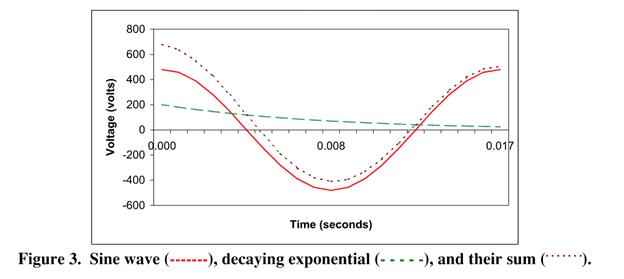
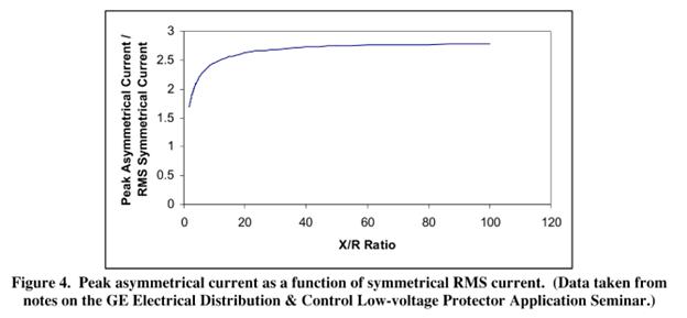
The top graph shows us the sine curve of the symmetrical fault current as well as a decaying exponential that is generated largely as a function of X/R ratio. The summation of those two curves results in the asymmetrical fault current. The bottom chart nicely displays how X/R ratio affects the magnitude of the peak asymmetrical fault as it compares to the RMS symmetrical fault. This chart is specific to a certain type of electrical equipment, but the general idea applies universally. The larger the X/R ratio the larger the peak asymmetrical fault that could be generated. This must be taken into account when selecting overcurrent protective devices and equipment designed to withstand fault conditions.
Finally, does X/R ratio change depending on the type of fault?, specifically, I looked into a 3phase line fault vs a single line-ground fault. In order to answer this question, we will look at the theory of symmetrical components. There are 3 components associated with a balanced 3-phase system; the positive sequence ‘Z1’, negative sequence ‘Z2’, and zero sequence ‘Z0’ components. I don’t claim to fully understand symmetrical components, but the research I have done suggests that they are an essential means for analyzing fault conditions in power systems.
Given those equations, we can infer that the overall impedance of a ground fault will be different than that of a line fault given the ground path. Since ground paths are predominantly just conductors, I believe it is safe to assume that the resistance part of the overall impedance would increase and bring the overall X/R down for a ground fault when compared to a 3ph fault. This is in part why line faults are almost always larger than ground faults; the X/R ratio is larger and so the asymmetric fault current is larger.
The positive and negative sequence impedances are generated by circuit components such as transformers, conductors, utility, etc. While the zero sequence impedance results from current flowing on something
other than the phase path, usually this is the ground path and so zero sequence is predominantly present during a ground fault condition.
Therefore, in a 3ph fault, there is positive and negative sequence impedances present and the fault current is determined by the equation I3ph = V/Z1
In a line-ground fault, there is positive, negative, and zero sequence impedances present, and the fault current is determined by the equation Iline-gnd = (3*V)/ (Z1+Z2+Z0)
Either way, you can’t assume that the X/R ratio for a 3phase line fault is the same as the X/R ratio for a line to ground fault. These values must be solved for if you know the power factor of your system or you would need to gather additional information on the fault current, available from your utility.
Hopefully this article finds you well and can be used as a reference for your project needs.If anyone would like to contribute to the Rochester Engineer and add an article or would like to request information on a specific topic (not limited to Electrical) just email Brett Eliasz at beliasz@bergmannpc.com. As always, any comments are appreciated! Thank you for reading.
Brett Eliasz, P.E., LEED AP BD+C , RES Director
Joshua Doores, Electrical Engineer Colliers Engineering & Design
You may be familiar with the concept of the impedance triangle which is used to visually demonstrate the components that make up impedance and the phase angle between them. See figure below. As you can see, the larger the inductive reactance the larger the phase angle and the more voltage leads current, and the two waveforms become more out of phase.


