Sensible & Latent Energy Recovery Systems
Hardi ShahABSTRACT
Heat recovery systems are becoming widely integrated into HVAC systems in a myriad of climate and program typologies. Air conditioning and ventilation are two of the largest energy and financial costs of a structure, making waste heat recovery an essential component in HVAC systems. Waste heat from various processes within the building system is reused in varying heat recovery technologies to significantly reduce the load on the heating or cooling system. The applications vary greatly from industrial heat recovery to high-energy lab program heat recovery to residential small-scale heat recovery and various types of recovery systems are suited for these differing applications. The various types of heat recovery, their mechanisms, working principles, and their practical applications are discussed in this paper.
The Basics of Energy Recovery
Due to rising concerns about climate change and the energy crisis plaguing the globe, an interest in waste heat recovery systems has grown. An integrated system consisting of energy-efficient MEP systems and waste heat recovery is a rewarding approach to increasing performance and reducing generation of greenhouse gas emissions. In terms of global energy demand, buildings currently account for 40% of the total due to overall building energy consumption, operation, and maintenance. Of this, the heating, ventilation, and air conditioning (HVAC) systems consume 40-60% of a building’s energy depending on climate. Due to the sheer significance of the statistics of HVAC energy consumption, governments are pushing and encouraging the development of energy-saving building technologies. One such technology is waste heat recovery (Qi Xu 2019).
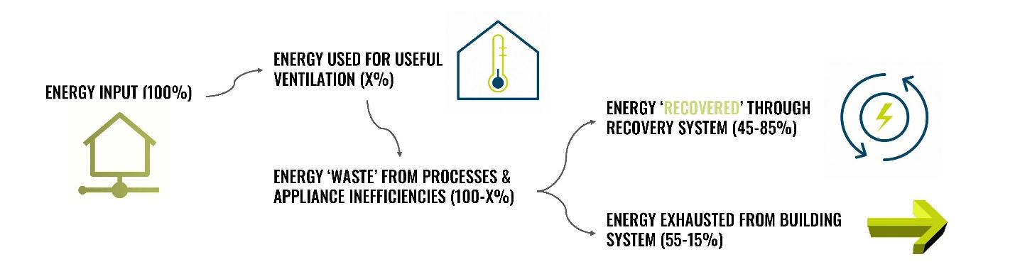
Energy recovery systems must balance between reducing overall energy loads as well as providing acceptable or improved indoor air quality. Recovery systems are typically a device operating between two sources at varying temperatures and facilitating a transfer of energy from the high energy source to the low energy source (ASHRAE 2020). The various types of recovery system exchangers can recover up to 6095% of waste energy which significantly reduces the energy consumed by an air handling unit’s energy to condition fresh outdoor air to a comfortable indoor temperature and humidity (Qi Xu 2019).
In terms of HVAC system costs, building managers typically economize and balance between the high cost to condition air and the indoor air quality. Many managers will opt to recirculate air in lieu of conditioning fresh air to save on costs. Therefore, in addition to energy consumption reduction, an energy recovery system can provide more efficient air ventilation with a higher frequency than traditional HVAC systems resulting in cost-effective ventilation improving indoor air quality (ASHRAE 2020)
Figure 1 The Basics of Energy Recovery
Types of Waste Heat Recovery
From a study conducted in Beijing, it was found that 30%-60% of the total energy consumption used for ventilation is lost through inefficiencies in the HVAC system (Yiyu Men 2022). Due to the significant percentage of loss through those inefficiencies, it becomes imperative to incorporate technology such as waste heat recovery which can reduce that percentage of waste heat being exhausted and increase the efficiency of HVAC by reducing the energy needed to condition air. Waste heat recovery can transfer heat or enthalpy between the return air and the incoming fresh air stream, tempering the incoming air before it reaches the air handling unit resulting in lower energy expenditure to transform fresh air into usable supply air with specific temperature and humidity properties.
An exhaust air stream is typically at the required indoor temperature and humidity. Depending on the site of the building and climate, the incoming fresh stream of air is likely of a much different enthalpy. If the exhaust air has a higher enthalpy than the incoming air, the HRV or ERV will facilitate a transfer of enthalpy from the stream of higher enthalpy to the stream of lower enthalpy. Based on the efficiency of the HRV or ERV, a certain percentage of the enthalpy will be successfully transferred resulting in a stream of incoming air at an enthalpy much closer to the indoor air conditions. This in turn reduces the conditioning work that needs to be done by the air handling unit by reusing the exhaust air on which the work had already been done. The benefit to heat recovery systems is that because the AHU only has to expend the energy to bring the HRV or ERV tempered fresh air to indoor conditions, the building can circulate more fresh air using much less energy. This drives the cost of ventilation down and allows for better indoor air quality.
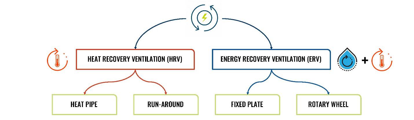
Based on the second law of thermodynamics, heat energy always transfers from a region of high temperature to one of low temperature. Mass, or humidity, transfer always occurs from a region of high vapor pressure to one of low vapor pressure Waste heat recovery can be split into two overarching typologies: the first type is sensible heat recovery and the second is latent heat recovery. Sensible heat is related to changes in temperature of a gas or object with no change in phase. Heat is transferred when there is a difference in temperature between the two sources. Latent heat is related to changes in phase between liquids, gases, and solids. In heat recovery, this refers to moisture transfer. Moisture is transferred when there is a difference in vapor pressure between the two airstreams (ASHRAE 2020) Heat recovery ventilation, or HRV, describes an energy recovery mechanism which transfers only sensible heat while energy recovery ventilation, or ERV, is a mechanism which transfers both sensible and latent heat. Based on the different constructions, heat recovery systems can be categorized into four types: heat pipes, runaround, fixed plate, and rotary wheel. Heat pipe and run-around systems are HRVs transferring only sensible heat while fixed plate and rotary wheel systems are ERVs and have the capacity to transfer both sensible and latent heat (Qi Xu 2019).
Figure 2. The Umbrella of Heat Recovery Energy Recovery Heat Pipes (HRV)

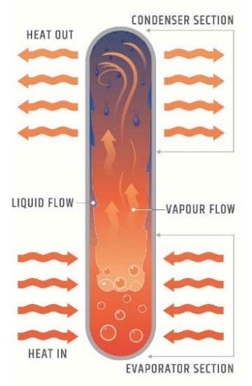
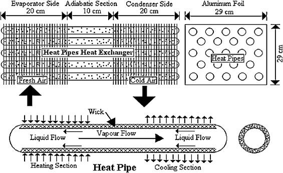
Heat pipes combine the principles of heat conduction and phase change to effectively transfer heat between two sources. Heat pipes are great for uses that require high sensible heat recovery. The construction of a heat pipe is a vacuum sealed pipe with a working fluid inside. The core of the heat pipe is where the vapor travels while the wick is where the condensate returns. The working fluid is subject to the vacuum and pressure inside the pipe and therefore has a much lower boiling point (Hassam Nasarullah Chaudhry 2012). This principle allows the working fluid to absorb heat from its surroundings and boil, resulting in a change of phase from liquid to gas. Because it takes more energy to heat a liquid than a gas, the working fluid effectively absorbs more heat from its surroundings and reaches its boiling point within the vacuum sealed pipe. In an air-to-air heat exchange system, the exhaust and incoming air at different temperatures are arranged to flow over the two separate ends of the pipe. The portion of the pipe in contact with the source at a higher temperature (evaporator section) absorbs the heat causing the liquid within to change phase and vaporize. The vapor pressure gradient then drives the resultant vapor to the opposite end of the heat pipe (condenser section) and changes phase once again condensing into a liquid, releasing the latent energy of vaporization into the cooler source. The adiabatic section of the heat pipe is the central portion where the vapor and liquid phases of the fluid flow in opposite directions. Typical heat pipe exchangers can achieve thermal efficiency of around 50% (Qi Xu 2019).
Because a heat pipe has no moving parts and does not require an external electricity input, it is an efficient way to transport large quantities of heat over large distances with almost an invariable temperature (Hassam Nasarullah Chaudhry 2012) The effectiveness of the heat pipe largely depends on the working fluid, the arrangement of the pipes, the velocity of the sources passing over the surface area of the pipe, and the inlet temperature of the evaporator section. Because the working fluid exists within a closed loop evaporation and condensation cycle, the heat pipe will operate successfully as long as there is a temperature difference between the two ends of the pipe to drive the process. Typically, there is collection of similar heat pipes aligned in a tubular arrangement either vertically, horizontally or aligned at an angle meant to increase the surface area of the pipes that will transfer heat from the hot to cold sources (see Figure 3) The more rows there are, the higher the contact surface area, the greater the effectiveness of temperature
absorption and transfer. The slope of the heat pipe impacts the speed at which the condensate will flow back to complete the loop. The greater the slope, the quicker the condensate can flow back to the evaporator section to absorb heat and vaporize once again The success of the closed loop mechanism also depends on how significant the temperature difference is between sources. The higher the temperature difference, the more effectively the heat will be transferred through the pipe. The working fluid’s physical properties also contribute greatly to the successful transfer of heat energy. The internal liquid must have a high latent heat of vaporization, a high surface tension, a low liquid viscosity over the operating range, and it must be thermally stable at operating temperatures.
The operating temperature of the heat pipe is determined by the use case of the heat pipe. The operating pressure and working fluid within the heat pipe depend on that operating temperature. If a heat pipe needs to remove heat from a source at X temperature, the pressure inside the pipe must be maintained at the pressure for which the working fluid would boil at X temperature (Hassam Nasarullah Chaudhry 2012).
For air-to-air heat exchange it is typical to see aluminum or copper tube materials with aluminum or copper fins for temperatures below 220oC Heat pipes are able to transfer heat at up to 1000 times the rate of heat transfer through copper, a known conductor (ASHRAE 2020). Water is typically the working liquid of choice for use cases such as HVAC at temperatures between freezing and 220oC. For sub-zero temperatures, liquid helium is used and for extremely high temperatures over 220oC, liquid metals such as potassium, sodium, and lithium are required (ASHRAE 2020)
Figure 3. Heat Pipe Arrangements and Construction
Heat Pipes Along the Alaskan Pipeline – Geotechnical Application
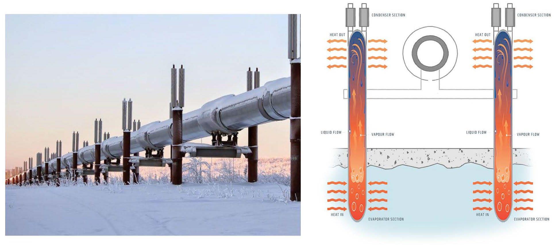
Apart from an HVAC usage, heat pipes have also been used to slow the thaw of permafrost in cold climates such as Alaska and Siberia. The Trans Alaska Pipeline is a combination of a large pipe, twelve pump stations, a network of roads and airfields, and a series of construction camps. It was imperative that the pipeline was constructed in a fail-safe manner using state-of-the-art technology. Where possible, the pipeline’s routes were altered to avoid poor soil thermal conditions. However, where that was not possible, heat pipes were used to provide ground cooling during the winter.
In this application, the heat pipe is placed vertically in the ground with the condenser section above and the evaporator section below. The working liquid is pooled at the bottom of the heat pipe in the evaporator
section while the rest of the pipe is filled with the vapor of the working fluid (Heuer 1979). The air temperature is colder than the ground temperature in the winter so as the air temperature falls below the saturation temperature of the vapor, some vapor condenses releasing heat into the air. As the condensate flows down the pipe wall or down the wick, it creates a pressure gradient and lowers the gas pressure below the saturation pressure of the liquid in the evaporator section. This causes the liquid to evaporate and absorb heat from the soil. The evaporated vapor then flows upward and condenses again in the above-ground portion of the pipe completing the cycle. The natural convection cycle is then established moving heat from the soil to the atmosphere as long as the air temperature is colder than the soil temperature. The heat pipes are effective even in this setting with a vast array of variables because heat pipes need only a fraction of a degree to operate and can establish this convection cycle in less than an hour (Heuer 1979)
Figure 4. Alaskan Oil Pipeline
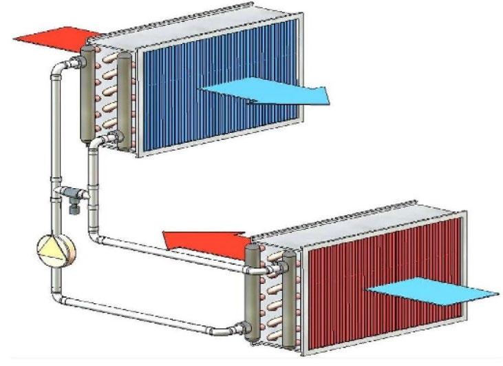
Run- Around Energy Recovery (HRV)
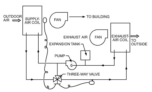
Also known as coil energy recovery loops, run-around loops are two extended-surface, finned tube water coils in the two separate intake and output sources. These two coils are within a closed loop system and connected by piping arranged in a counterflow pattern. An intermediate heat transfer fluid like water or anti-freeze solution is pumped through the pipe which successfully transfers sensible heat from the hotter source to the cooler source. There is a three-way control valve which maintains the temperature of solution entering the exhaust coil at 5oC or above to prevent the coil from freezing.
The benefit of using run-around loop energy recovery is that they require little maintenance because the only moving parts are circulation pump and three-way control valve. These systems are also widely used for industrial purposes because they accommodate remote locations for the supply and exhaust ducts making them flexible in application. The total separation of exhaust and supply streams also means there is no possibility for cross contamination between the sources. While moisture cannot be transferred between the two streams, indirect evaporative cooling can reduce the exhaust air temperature which results in lower cooling loads. Depending on the application, the thermal transfer fluid varies. An inhibited ethylene glycol solution in water is common when freeze protection is needed but the temperature does not exceed 135oC. For applications where exhaust temperatures exceed 135oC and freeze protection is needed, a nonaqueous synthetic heat transfer fluid is used (ASHRAE 2020).
Run-around loops have a sensible effectiveness between 55% and 65%. As previously mentioned, this system is well suited for industrial applications and that is because run-around loops are able to transfer energy without contamination between process loads and ventilation supply. As an example, a run-around
loop could be used to absorb rejected heat from a water-cooling system and then transfer that heat to the HVAC system which can use it to preheat outside air (Reilly 2003)
Figure 5. Run-Around Energy Recovery in HVAC
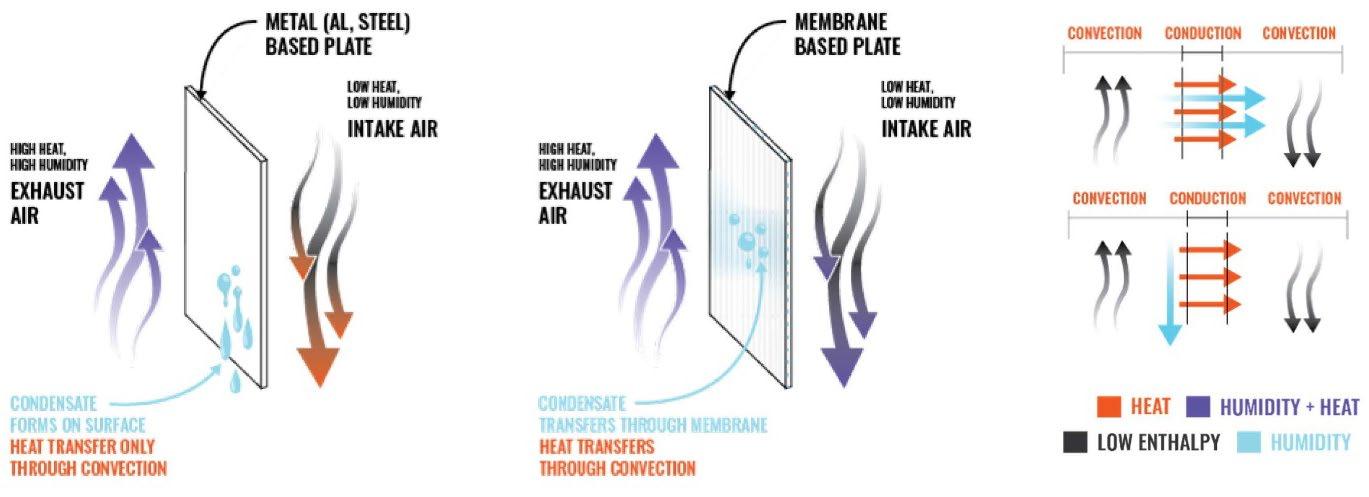
Fixed- Plate Heat Recovery (HRV/ ERV)
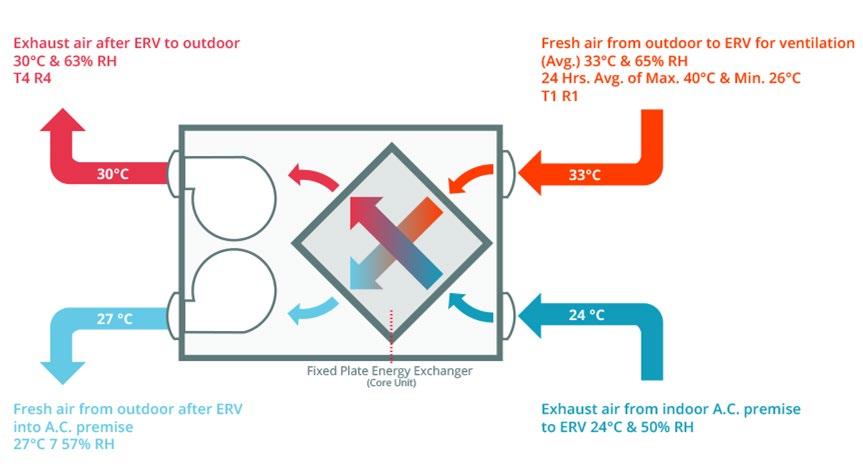
Fixed plate systems can be either an HRV or an ERV as they are capable of transferring both sensible and latent heat depending on the material used for the plates, plate arrangement, and air flow pattern. They use the principles of convection and conduction to transfer heat between the flow channels created by stacking thin plates together. It is a static device with no moving parts except for the two airstreams crossing each other in a parallel-flow, crossflow, or counter-flow configuration. The plates are thin and have a large surface area with high thermal conductivity giving each plate a high heat transfer rate (ASHRAE 2020).
Fixed-plate energy recovery can reach efficiencies between 50 and 80% depending on the air flow rate and the heat transfer rate of the plate material. A slower air flow rate results in a higher residence time, allowing for more heat and mass to be transferred from the higher enthalpy source flow to the plates through convection, then through the plates by conduction, and then from the plate to the lower enthalpy source flow through convection. In that process, if it is an ERV, moisture is diffused through the membrane of the plate (ASHRAE 2020)
Figure 6. Fixed Plate Energy Exchanger Diagram
In an HRV where only sensible heat is transferred, if either of the air streams is of high humidity, it will cause condensate to form on the plates slightly dehumidifying the humid air. That condensate must
then be removed with a drain. For HRV fixed-plate systems, the material of the plate depends on the use of the system. Steel alloys are used for specialized applications with temperatures over 200oC. Polymer plates are corrosion resistant and cost effective so would be ideal for an application with a possibly fouling or corrosive exhaust. Aluminum plates are the most widely used due to their operating temperature being around typical HVAC requirements and their inflammability and durability (ASHRAE 2020)
For an ERV fixed-plate system, both sensible and latent heat is transferred through a water-vaporpermeable material such as treated paper and microporous polymeric membranes. There are many material types that can be used in this system which are available through manufacturers. New materials are also being researched. Due to the molecular shape of water, when humid air is passed through the core it acts as an excellent solvent that bonds with the polar molecules of the core surface resulting in effective sorption. Then once those molecules make contact with the other air stream at a lower enthalpy, they are picked up and transferred resulting in an increase in relative humidity. A higher relative humidity level of an air stream results in higher moisture absorption so if the goal of the system is to transfer a large percentage of latent heat, it would be more effective with an air stream of high moisture content
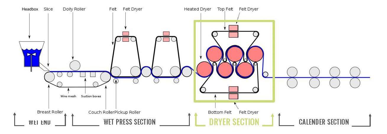
Fixed- Plate Heat Recovery in the Paper Industry
Overall, pulp and paper mills are one of the five largest industrial energy consumers. At pulp and paper mills, the industrial paper-making process involves four sections:
• The wet end where the wood chips from the trees are mixed with water and turned into a pulp
• The wet press section where the pulp is pressed flat and the water from the pulp is absorbed by the felt.
• The dryer section where the felt continues to press into the pulp but it is then dried to remove the water from the felt before it is pressed into the pulp again. This section consumes more than 60% of the total energy demands of the paper making process (Jacob Geist 2021).
• The calender section where the pulp is sent through rollers flattening it out. This is also where the finishes of the paper are applied to the flattened pulp.
Typically, this dryer section requires large investments in equipment, from purchase to operating costs. If the heat that is used and released within the dryer process is recovered and reused, it would result in higher efficiency. The exhaust from the dryer contains small amounts of cellulose and resin making it difficult to incorporate traditional heat exchangers without worrying about clogging or fouling (Jacob Geist 2021).
Figure 8. Industrial Paper Making Process
As an alternative, assembled-plate energy banks are installed in line with the dryer exhaust. A cool liquid, typically water or a glycol mixture, is pumped in on one end of the bank cooling the plates as it flows through. The hot exhaust transfers the sensible heat onto the plates at a high efficiency due to the higher heat transfer coefficient of a condensing vapor. This heat is then transferred into the liquid that is flowing through the plates. The liquid absorbs the heat energy from the exhaust via the plates and is collected in a separate location and is later reused through the facility as an alternative heat source. These energy banks are averse to fouling because the exchange surface is smooth and the surface area of the plate is constantly being self-cleaned with the condensate that forms when the hot, humid exhaust passes over cool, fixed plates (Jacob Geist 2021)
Figure 9. Heat Recovery within Industrial Paper Making Process
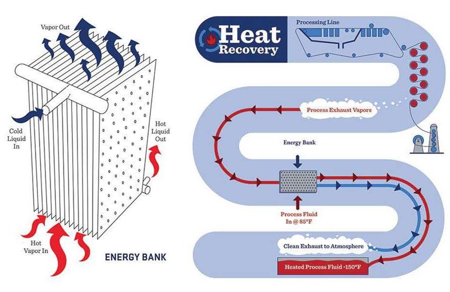
This fixed-plate energy bank configuration can be applied to any use-case that has a hot, condensable process stream: ethanol refineries, chemical processing facilities, grain processing plants, etc.
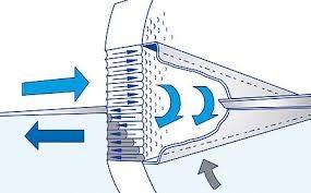
Rotary Wheel Energy Recovery (HRV/ ERV)
Like fixed-plate systems, a rotary wheel can also be used as either an HRV or ERV depending on the properties of the heat exchange material inside the wheel. A rotary wheel is a revolving cylinder filled with an exchange material that has a large internal surface area positioned between two air streams. The structure
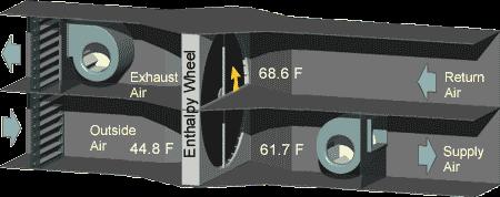
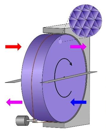
of the unit is built out of aluminum, the casing for the wheel is steel, and the materials of the rotor are polymers. The supply and exhaust air streams flow in adjacent, opposite directions through half of the exchanger each in a counterflow pattern. As one stream at a higher enthalpy passes over the wheel, the wheel absorbs the sensible (and latent if it is an ERV) energy and rotates. As the wheel rotates, the absorbed energy in the wheel comes in contact with the other air stream at a lower enthalpy effectively releasing the energy into that air stream. As the wheel keeps rotating, the exchange media within it constantly transfers energy from the high enthalpy to low enthalpy air stream. The wheel rotation speed, heat exchanger material, and air flow pattern and speed are variables that can be designed to focus in different proportions on sensible or latent heat recovery (ASHRAE 2020)
Figure 10. Enthalpy Wheel Unit
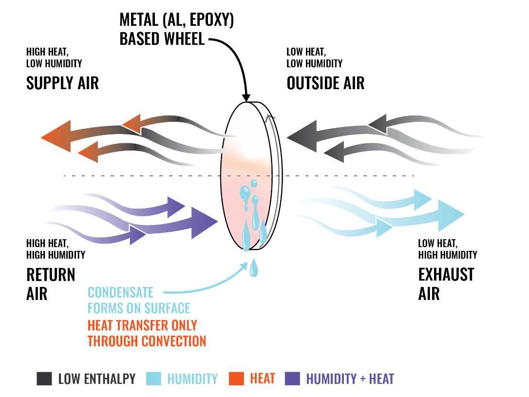
In an HRV, the sensible heat is transferred from the hot stream and released into the cold one. If either air stream passing by the wheel is at a high heat and humidity, the wheel will transfer the sensible heat but due to the condensation of the vapor on the wheel a small amount of latent heat will also transfer. Typically, the materials for an enthalpy wheel HRV, the exchange media is aluminum or epoxy. In an ERV, the wheel will transfer sensible heat driven by temperature difference as well as latent heat driven by the vapor pressure difference (ASHRAE 2020).
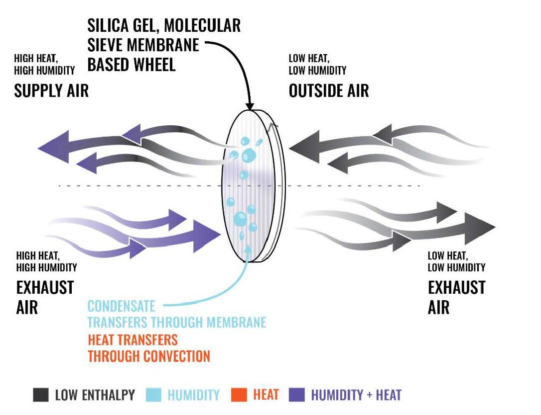
Exchange media can range from metal, mineral, or synthetic materials and can provide either random or directionally oriented flow through their internal structures. Random flow media requires a larger face area than directionally oriented media due to the increased resistance of randomly oriented airways. Random flow media also can only be used for clean, filtered airstreams because they could clog easily. For below 220oC temperatures, aluminum mesh is the typical material used while stainless steel and Monel mesh are used for temperatures above 220oC. Directionally oriented media are parallel air passages in the direction of airflow making them a better choice for airstreams that may not be filtered. Aluminum, paper, plastic, and synthetic materials are used as exchange media for below 220oC temperatures while stainless steel and ceramics are used for high temperatures or corrosive air conditions (ASHRAE 2020)
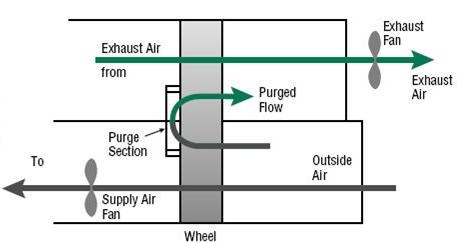
Figure 13. Rotary Wheel Purge Section
One of the disadvantages of a rotary wheel is that the heat exchanger media comes in contact with both air streams and risks cross contamination if the air streams are not filtered. Particulate matter, carbon dioxide, and harsh chemical fumes could all contaminate air flows. Many programs are required to have high indoor air quality compared to others such as offices, schools, public institutions, labs, hospitals, etc. (Kassai 2017) This movement of particulate from exhaust to supply airflow by way of the wheel surface is known as carryover. By introducing a purge section which pushes fresh air through the media in one location and then immediately pushes it out through the exhaust flow as shown above, carryover can be reduced to less than 0.1% of the exhaust flow.
Rotary Wheel Energy Recovery in Walter Reed National Military Medical Center
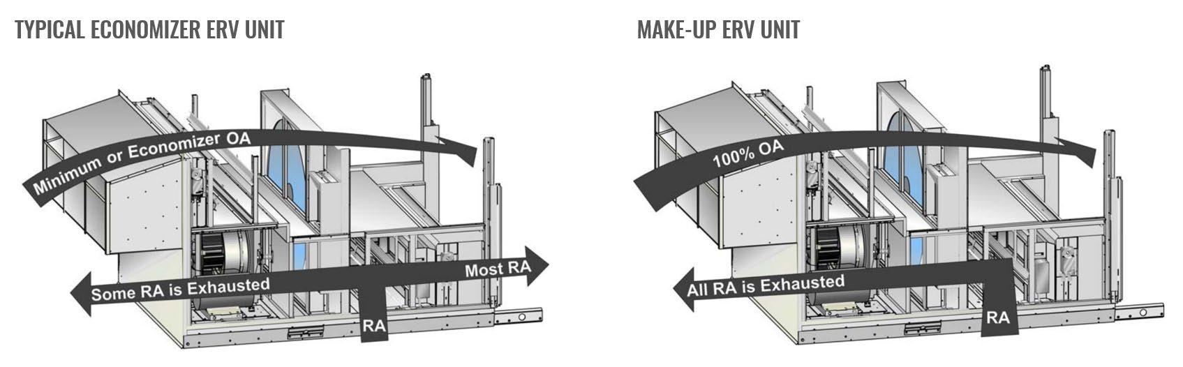
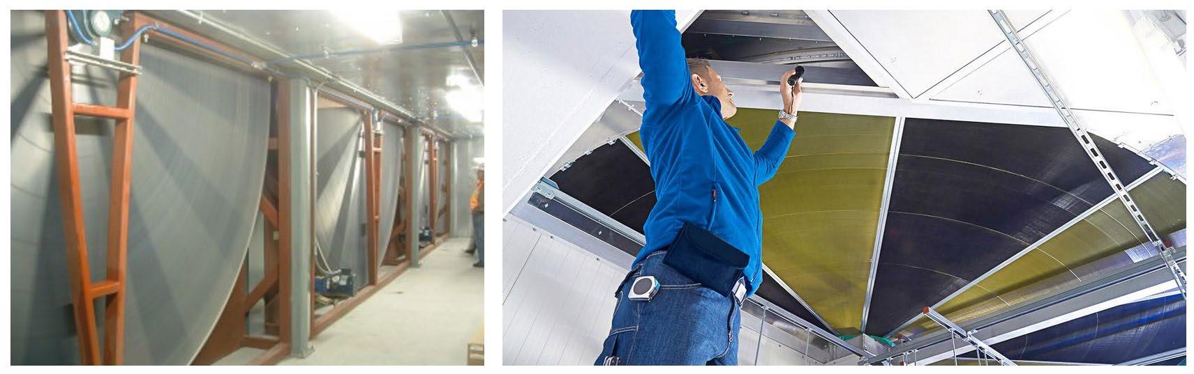
The Walter Reed National Military Medical Center is a 515,000 square-foot ambulatory care building with a 162,000 square-foot hospital addition, a 450,000-square-foot hospital renovation, and a 943-space parking structure. When the Walter Reed National Military Medical Center was being renovated, there was an emphasis on providing 100% fresh outdoor air to improve indoor air quality.
Typically, in air handling units, a portion of the exhaust air is recycled as return air to save on the energy that it would take to condition 100% outdoor air to acceptable indoor air requirements. This is known as the economizer unit. The 100% outdoor air system used provides 100% outside air because the enthalpy wheel is able to reduce the energy used to condition the 100% outdoor air intake by transferring the enthalpy between the exhaust and supply before expelling the exhaust air into the atmosphere. Because it uses only two ducts for supply and exhaust instead of the typical three (supply, exhaust, and return) the enthalpy wheel exchanges enthalpy between the exhaust air and outside air but does not recycle any exhaust air back into the space. There was limited space in the ceiling due to the project being a renovation of an existing facility and the reduction of the return air duct made it easier to install the HVAC system. The facility houses eleven 16-foot diameter enthalpy wheels, and it reduced the hospital’s HVAC costs by a substantial 28% (Shiminski 2012).
Architectural Applications of Heat Recovery
Within the past decade, the integration of heat recovery with building components such as building walls, roofs, floors, and wind towers has been considered. This type of integration is able to stabilize the heat flux of buildings resulting in a reduction of total energy demands. Research is still on-going and there is not enough real-life testing to investigate durability, cost, and easy operation. The research is largely conducted in one climate zone and does not have enough variation in climate for accurate overall assumption. Outdoor pollutants and other atmospheric issues are typically ignored within the studies.
Roof Type Heat Recovery Panel
This study was conducted in the winter season in Kent, UK. Because residential domestic buildings have the largest share of building energy consumption at 63% and most of that energy is used for HVAC, a low-cost, user-friendly heat recovery system for domestic application was considered. The proposed system’s constituents are a plate-type heat exchanger, blower fans, and ducts and is designed to have an under-roof application. The material of choice is a polycarbonate sheet for its light-weighted-ness, costeffectiveness, and its resistance to mineral acids, organic acids, greases, and oils. It has an HVAC applicable service temperature of -4 to 135oC. Four polycarbonate sheets are arranged: two at the front of the small test house building and two at the back. The full system is well insulated so as to not have heat loss during the transfer. The end of each polycarbonate sheet is connected to an extract or inlet duct which connects to the HVAC ducts and eventually to the fans. A convective heater was placed on the interior of the house to keep the interior temperature constant (Pinar Mert Cuce 2016)
Figure 16. Schematic of Roof Heat Recovery System
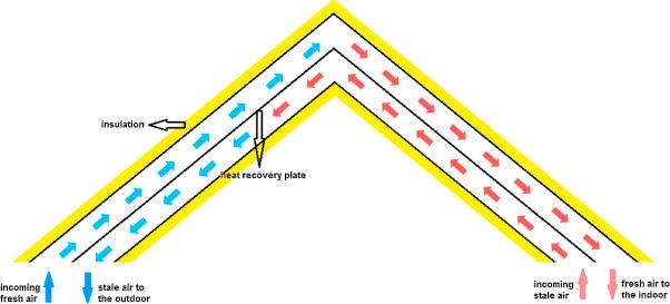
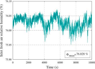
Fresh air from the outdoors is preheated by the waste, stale air that is collected from the bathroom with a fan because both air sources pass through the polycarbonate sheet fixed-plate heat exchanger. Due to the nature of the material, latent heat is also able to transfer from the humid bathroom exhaust to the incoming fresh air. Inlet fresh air temperature, inlet fresh air relative humidity, inlet stale air temperature, inlet stale air relative humidity, mass flow rate, and fan speed were measured as input data. That data was used to calculate the results of the system: an 89% heat recovery efficiency and a coefficient of performance of 4.5. This system tested to have a payback period of around 1.7 years (Pinar Mert Cuce 2016)
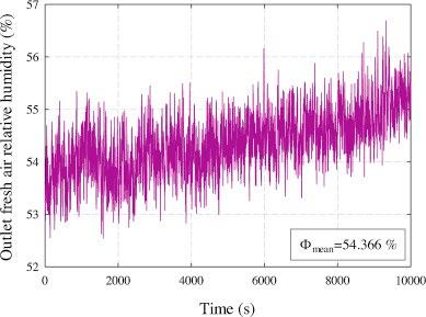
These graphs show the decrease in relative humidity from the inlet fresh air to the outlet fresh air that would later become supply. The inlet fresh air hovers between 76 and 76.1% relative humidity but after passing through the roof integrated fixed plate exchanger, the relative humidity is brought down to a comfortable range between 52 and 57% (Pinar Mert Cuce 2016)
Figure 17. Relative Humidity Records
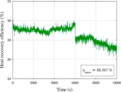
The heat recovery efficiency is high between 86 and 90% while COP is also high between 3.5 and 5. When the efficiency and COP are mapped onto a chart, the general trend is a decrease in both with time. This is likely due to the saturation of the heat exchange material (Pinar Mert Cuce 2016)
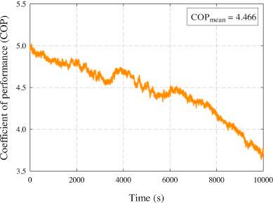
Figure 18. Heat Recovery Efficiency per Time (left) and Coefficient of Performance per Time (right)
The limitations to this study are due to the single climate zone it was tested in as well as the small size of the residence. A building would also have a varying indoor temperature and with how much of the surface area of the roof is in contact with interior spaces, that variation might affect the heat transfer if the insulation around polycarbonate is not sufficient year-round. The bathroom exhaust air that is used to preheat the incoming fresh air is also highly variable. The bathroom is not always generating the same type of exhaust which would vary the results as well.
Passive Solar Heating System: Wall Implanted with Heat Pipes
With the driving force being the focus on the wall as the key to energy saving in a building enclosure, the study explores a way to make the wall’s thermal resistance variable instead of traditionally constant. While the thermal properties of a wall might be more beneficial in one season, it could be adding to the energy demands in another. If the wall has a higher thermal resistance, heat is unable to be transferred into the building but if the wall has a lower thermal resistance, the heat transfer will increase the inside temperature of the wall to reduce heating load. In the hotter months, when the temperature of the outside
surface of the wall is lower in the nighttime than the inner surface, having a lower thermal resistance will facilitate better heat dissipation reducing cooling loads and improving thermal comfort. (Zhigang Zhang 2014)
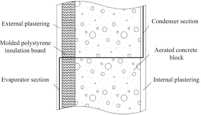
Previously tested solar-thermosyphon embedded radiant flooring was a significant improvement on a solar heating system, which is an indirect passive solar heating system that provides a high percentage of the total heat necessary in a room to ensure comfortable conditions. That brought forth the concept of a Wall Implanted with Heat Pipes (WIHP)
Micro-gravity heat pipes are embedded into the plastering mortar outside of the insulation board and are relatively thin in size compared to the other structural elements of the wall. The WIHP does not hinder structural performance of the wall and results in a composite wall with phase-change, heat storage, and heat release. Due to the efficient heat transfer of heat pipes, even a small degree of temperature difference drives the heat transfer from outdoor to indoor in the winter while it is from indoor to outdoor in the summer (Zhigang Zhang 2014).
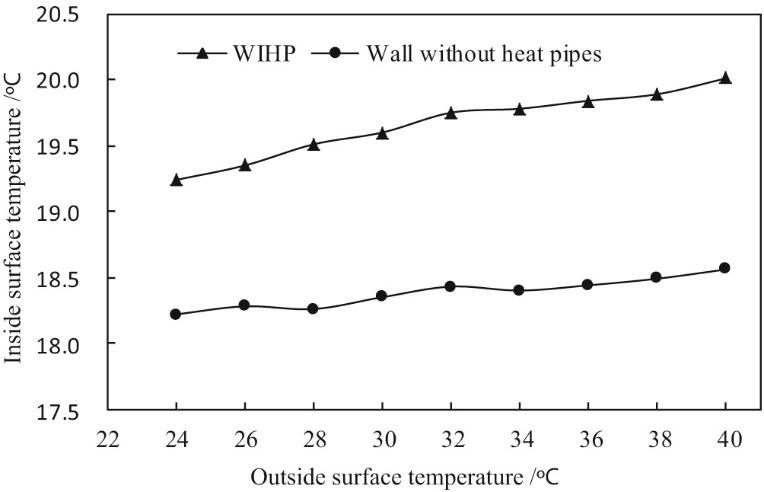
The WIHP is meant to solve the contradicting relationship between outer envelope insulation and the usage of energy to maintain a comfortable indoor environment. The graph to the left depicts the inside surface temperature that was recorded for a WIHP as well as a wall without embedded heat pipes. It was deduced that the use of WIHP greatly improves the interior thermal conditions with the average inside surface temperature of the WIHP being 1.28oC on average (Zhigang Zhang 2014)
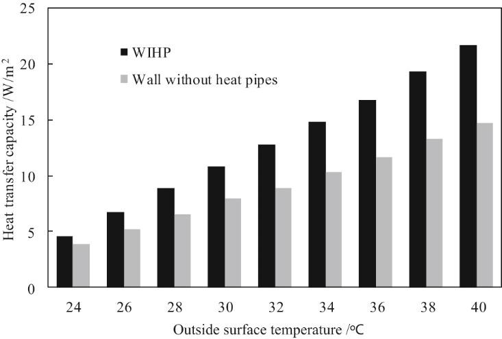
The heat transfer capacity per unit area of the wall and WIHP under different outside surface temperatures are plotted to the left. The WIHP can transfer on average 3.763 W/m2 more than a traditional wall. Therefore, the heat transfer capacity is enhanced by introducing the heat pipes into the wall construction (Zhigang Zhang 2014)
How to Measure Performance and Effectiveness
ASHRAE Standard 84 describes uniform testing methods, outlines the required calculations, data, and reporting methods, as well as guides selection of testing equipment. Independent performance factors to be tested are:
1. Sensible, latent, and total effectiveness
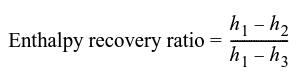
2. The enthalpy recovery ratio
3. Supply and exhaust air pressure drops
4. Exhaust air transfer ratio – fraction of exhaust air transferred to supply air
5. Outdoor air correction factor – ratio of supply inlet to outlet airflow
For outdoor air correction factor (OACF), the OACF should be greater than 1 meaning the leakage is from the supply to the exhaust streams. The ideal exhaust air transfer ratio (EATR) should ideally be 0 assuming there is no leakage from the exhaust air to the supply air stream.
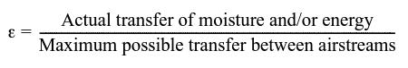
AHRI Standard 1061, based on ASHRAE Standard 84, is an industry wide standard that was established to rate air-to-air HRV or ERV performance to be used for ventilation systems. For ventilation applications in buildings for heat recovery, as of 2019 ASHRAE Standard 90.1 regulates that the effectiveness of the HRV or ERV must be greater than or equal to 50%. Effectiveness is the difference in enthalpy of the outdoor air and supply air equal to 50% or greater of the difference between the outdoor air and return air enthalpies at design conditions (ASHRAE 2020). That effectiveness can be measured for sensible, latent, or total effectiveness. This metric measures the performance of the exchanger.
Figure 19. Airstream Numbering Diagram
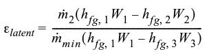
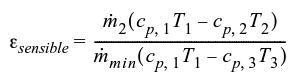
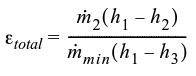
Here, the denominators express the theoretical maximum sensible, latent, or total energy transfer while the numerators are the measured metrics in the field under the conditions specified under ASHRAE Standard 84. The enthalpy recovery ratio represents the reduction in heating or cooling load associated with supply air and is represented by the formula:
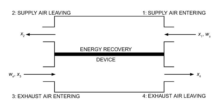
Where h is enthalpy at each station, ‘n’.
Essentially the formula maps out the ratio of the enthalpy difference between exiting supply air and entering supply air to the difference between the entering exhaust air to the entering supply air. For example, for a successful H/ERV in a cold climate, if the entering supply air has an enthalpy of 5 Kj/kg, the exiting supply air has an enthalpy of 19 Kj/kg, and the entering exhaust air has an enthalpy of 26 Kj/kg the enthalpy recovery ratio would be:
(5-19) / (5-26) = -14/-11 = 1.27
A ratio of 0.5 is needed to be acceptable under ASHRAE Standard 90.1.
For an unacceptable ratio in the same climate, if the entering supply air has an enthalpy of 5 Kj/kg, the exiting supply air has an enthalpy of 15 Kj/kg, and the entering exhaust air has an enthalpy of 30 Kj/kg the enthalpy recovery ratio would be:
(5-15) / (5-30) = -10/-25 = 0.4
Energy Recovery Study in ‘Laboratories for the 21st Century’ (HRV/ ERV)
Study Intent
Understanding the application of energy recovery in an energy and mechanical system intensive program allows for a deeper understanding of how this technology can be incorporated into design.
Since the technology’s debut over two decades ago, H/ERV has proven to be a rewarding addition to HVAC systems by bringing down energy use, improving efficiency, and reducing long-term cost. For HVAC intensive programs such as laboratories, typically 100% outside air is required at a high air change rate between 6 and 15 air change rate per hour. Compared to office programs, laboratories require 5 to 10 times the energy used to heat and cool the space. Requirements for design face velocity in laboratories are typically 500 fpm or less because they lead to lower pressure drops, lower operating costs, and ultimately higher effectiveness. However, to achieve this low face velocity, HVAC equipment needs to be robust resulting in high first costs. The addition of energy recovery in the HVAC system reduces peak heating and cooling load requirements allowing the typically extensive and cost-intensive HVAC systems to be downsized. This study aims to be a guide for designers and engineers by outlining various metrics to select the appropriate energy recovery system for a new construction (Reilly 2003)
Design Considerations to Determine Feasibility for Air-to-Air Heat Recovery
When deciding if air-to-air H/ERV’s are applicable to a project, there are several things to consider:
• Identify whether a manifold exhaust system is possible. It would gather all available potential energy that could be recovered in one place.
• Work out whether the supply and exhaust can be located next to one another or if they are in separate locations. The type of H/ERV that could be applied depends on the configuration of the two air/ source flows.
• In a warm, humid climate where dehumidification is needed, choosing an enthalpy wheel or wraparound loop are effective.
• Assess whether cross-contamination between exhaust and supply streams is possible and if it is a concern. Heat pipes and run-around loops pose no issues with cross contamination. Enthalpy wheels are able to include a purge section and bring cross-contamination below 0.1%.
• Address the capacity to which the exhaust or supply streams could corrode or foul the H/ERV.
• Determine whether the space & initial cost requirements of the H/ERV systems are possible to create within the HVAC system.
• In addition, determine whether maintenance, operation, and replacement costs are viable for the project.
• Address the cost benefit of downsizing the HVAC system due to the addition of the H/ERV.
• Assess whether the energy load of humidity control outweighs the energy used by H/ERVs like desiccant wheels performing dehumidification.
• Discuss the maintenance and operation of the H/ERV with the facilities manager. Some H/ERVs have higher maintenance and cleaning requirements and depending on the nature of the exhaust air, the maintenance might need to be more frequent.
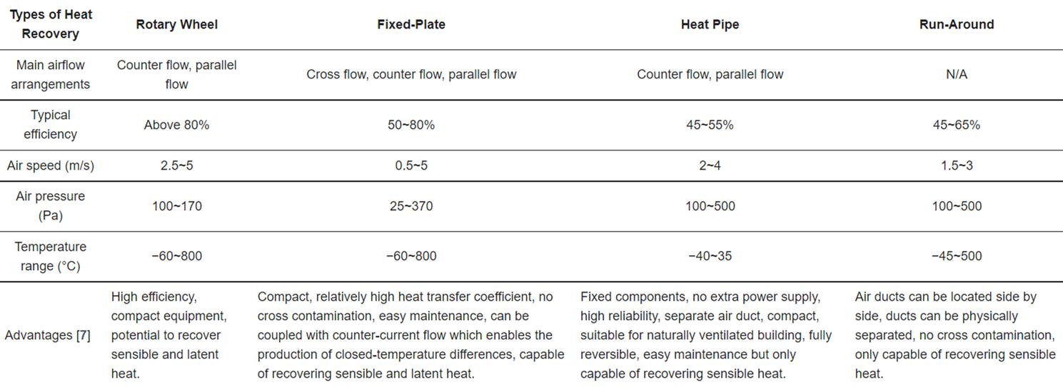
There are specific codes that address the performance requirements of energy recovery and whether it must or must not be included in the design. For laboratories specifically, the American Industrial Hygiene Association’s codes and standards are applicable (Reilly 2003). The following table could also serve as an initial look into choosing an H/ERV by discussing the mechanical design’s possible airflow arrangements, the type of recovery needed, the air speeds and pressures needed to achieve the efficiencies of each technology, and the needed temperature range of the project (Qi Xu 2019).
Figure 20. Comparison Chart for Heat Recovery Systems
Energy/ Cost Analysis for Recovery Systems in Varying Locations
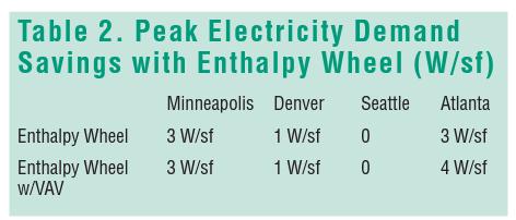
A typical 100,000 square-foot laboratory was analyzed in four separate locations: Minneapolis, Denver, Seattle, and Atlanta. A constant air volume system is assumed, and the electricity rate was a $0.03/kilowatthour (kWh) charge, the on-peak demand charge was $7/kW, and the off-peak demand charge was $4/kW. On-peak hours were assumed to be 8 AM to 10PM, Monday through Friday. The natural gas rate was assumed to be $0.60/therm (Reilly 2003)
For all climates, the gas usage for space heating and reheating for dehumidification was reduced by more than 35%.
Annual energy cost savings are $0.27 to $1.95/cfm of fan air flow. Enthalpy wheels recovering both sensible and latent heat were cost-effective in all climates
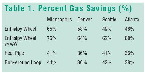
In warm, humid climates the cost savings from a heat pipe and run-around systems is relatively small. However, if those systems were to be used as a wrap-around loop for dehumidification, higher savings in cost and energy would be found.
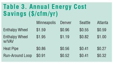
In the hot, humid climate of Atlanta the annual electricity savings occurred with the enthalpy wheel while in all other climates, the annual fan energy increase offsets the annual electricity savings.
Overall, HVAC cost and energy can be substantially reduced by properly designing the mechanical system by selecting the appropriate energy recovery technology and meeting applicable codes (Reilly 2003).
Relevant Codes & Standards
Current Regulations
• The Air-Conditioning and Refrigeration Institute (ARI) Standard 1060-2000 for specifically air-toair H/ERV rates the sensible, latent, and total effectiveness of equipment.
• American National Standards Institute (ANSI)/ ASHRAE Standard 84-1991 was mentioned previously as the institution which specifies the procedures to test effectiveness of the H/ERV.
• ANSI/ASHRAE Addendum p to Standard 62.1-2013: Ventilation for Acceptable Indoor Air Quality regulates the amount of cfm outdoor air that is needed per person (or per area) in different building programs. An energy recovery device is required if the supply airflow is ≥ 5,000 cfm
• In the International Mechanical Code (2003), section 514 covers the installation of H/ERVs while also prohibiting the use of energy recovery if the exhaust system identifies hazardous air.
• National Fire Protection Association (NFPA) 45 (2001) restricts the use of H/ERV on only general exhaust if there is a chance of cross-contamination.
• ASHRAE Standard 90.1 requires an H/ERV for any system bringing in 70% or more outside air.
• ASHRAE Standard 189.1 (2017): Standard for the Design of High-Performance Green Buildings Except Low-Rise Residential Buildings is a part of the International Green Construction Code. It is a newer development for H/ERV requirements. If a project is in a city which has adopted the IgCC, this code would be applicable. It is currently being specified for any buildings exceeding the air supply rates mentioned in Table 7.4.3.8 in the code. In addition, it requires a minimum efficiency of 60% (10% higher than the typical requirement) (Agopian 2019)
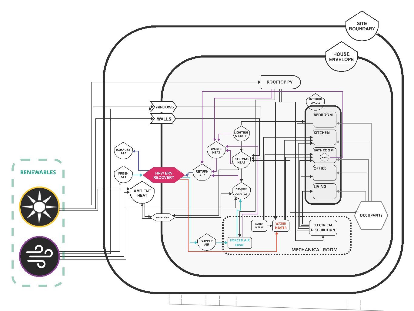
Emergy Diagram
In an emergy diagram of a home run on photovoltaics electricity generation and a forced air mechanical system, the inputs for an enthalpy wheel/ fixed plate/ heat pipe energy recovery (light blue arrows) are the two input streams of fresh air and return air (see Figure 10 for a diagram of the input streams). The return air is a combination of waste heat from all lights, equipment, ambient heat collected from solar radiation on the envelope and interior, internal heat gathered from occupants, and exhaust air and heat from the bathroom program. The recovered heat could be transferred directly to the input stream of the HVAC in the form of tempered supply air or if the exhaust heat was captured in some way, it could be used to heat water for domestic use. The fourth output stream of the H/ERV is the exhaust air that has passed through the heat exchanger material and is now dissipating into the atmosphere.
Figure 21. Emergy Diagram of an Enthalpy Wheel/ Fixed-Plate/ Heat Pipe Heat Recovery in a Residential Program
The depiction of the number of sources producing waste heat within a building (purple arrows that point to waste heat) is graphically telling of the amount of energy that is either wasted through dissipation or negatively impacting the efficiency of energy use in the space. The waste heat works almost in a positive feedback loop with the forced air HVAC system; the more energy expended by the HVAC, the more waste heat is produced causing the forced air system to work harder, expending more energy to offset the waste heat created by itself. The added efficiency of heat recovery breaks the positive feedback loop by reusing the waste heat and allowing the HVAC system to only expend the energy needed to bring the already tempered supply air to acceptable indoor conditions.