Defrost your evaporators, only when required WE INCREASE UPTIME, SAFETY AND EFFICIENCY Defrost On Demand DEFROST


Save energy and increase capacity
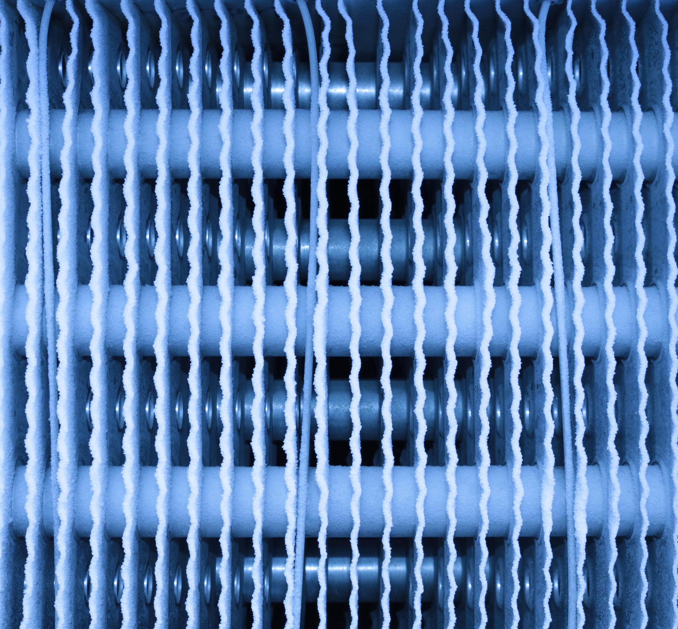
Ice buildup reduces evaporator performance and results in less cooling capacity.
Too much ice buildup will affect the air flow and reduce the heat transmission as ice acts as a thermal insulator.
• The heat transmission is reduced by 5 to 15% with an ice layer on 1.5 to 2mm (fin spacing 7mm).
The ice buildup on evaporators in cold storage applications changes throughout the year, as outdoor climate con ditions change. Traditionally, evaporator defrosts have been initiated based on a fixed time schedule, set to specific number of defrosts per day/week, regardless of whether a defrost is needed or not. During periods of the year where the climate has low humidity, typically during the winter months, ice on the evaporator surfaces builds up slower, and fewer defrosts are needed.
• Reduced air flow affects the cooling capacity from 20 to 100%.
DefrostPressSensorheretolearn
DEFROST
HBDF is a unique, but easily adaptable solution for automatic defrosting of evaporators. Optimal defrosting results in energy savings and increased freezing capacity. Experiences from existing in stallations have shown savings up to 40% of en ergy and thereby fast return on your investment.
The sensor can be used on evaporators with min imum 5 mm fin spacing in cold rooms. The sensor works on heat pumps, but it requires special con ditions and larger fin spacing. more
Save Energy And Increase Capacity
DEFROST Typical savings The largest savings are obtained for systems where a conventional timer based defrosting system is used and the humidity varies over time. This will cause reduced capacity and increased energy con sumption. In cold stores it is common to reduce the number of defrosting cycles by 50-70 % on a yearly basis. Calculations are needed on your system to get exact savings. *

Defrosting at the same ice thickness each time will reduce the frequency and duration of defrost, com pared to time-initiated methods. Demand driven defrost reduces the number of defrost cycles substantially.
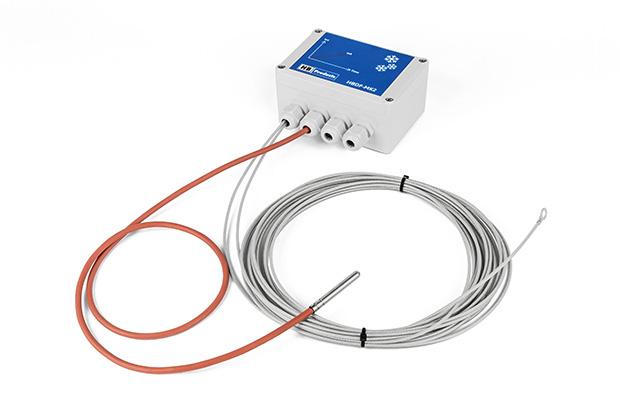
The defrost sensor is based on the capaci tive measuring principle, in which an insulat ed steel wire acts as one conductor and the evaporator fins act as the second conductor.
Demand driven defrost systems directly measure ice accumulation on the evaporator’s surface and initiate defrost only when required.
DEFROST
How does it work
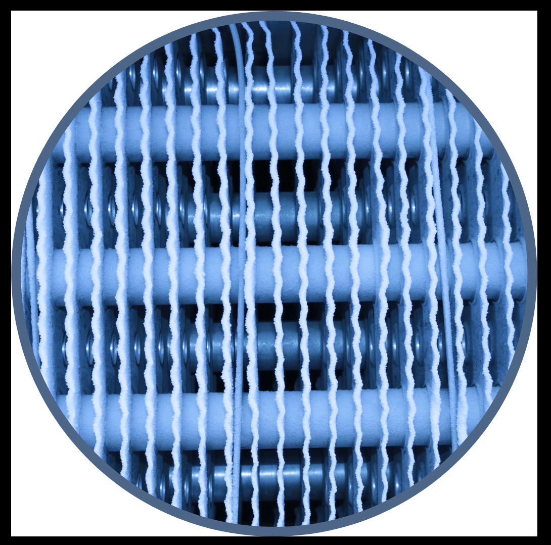
The sensor measures the ice thickness when the air is displaced by ice between the fins.
During defrosting, the pF value is measured, which can be used to start and stop defrost ing. When the defrosting has started, the ice becomes wet, whereby the pF value rises to a high level. When the ice has melted, the pF measurement drops again and stops defrost.
The output is either a 4-20mA analog output or/and a digital output send to a master con trol system.
Typical savings of minimum 20% to 40% in energy costs is achievable.
Defrost On Demand
Depending on the design of the system, the wire must be placed different.
DEFROST
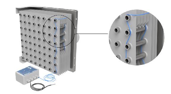
For liquid overfeed systems the wire is typically installed on the air inlet side
• For liquid overfeed systems ice is normally accumulated on the air inlet side.
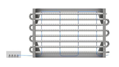
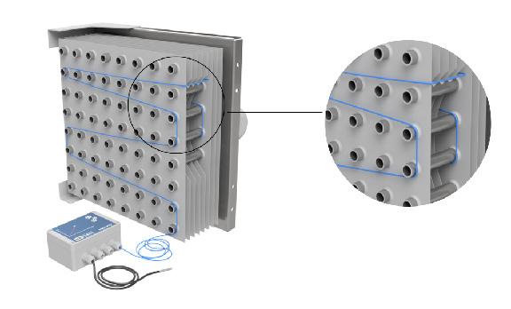
Sensor Wire Sensor Wire For DX systems the wire is typically passed through the evaporator
How to install
The wire is kept in place by the tubes and only needs to be long enough to get a representative measurement. Installation time will be approx. 1 hour per evaporator plus the controller (PLC) programming.
The coated wire is placed between the fins where the frost accumulates. If it is on an existing system, the wire is mounted where the ice layer gets thickest, this can be both be on the air inlet side, on the outlet side, or in the middle of the evaporator.
• For DX systems ice will accumulate in the middle of the evaporator as the air inlet is typically used for superheating of the refrigerant.
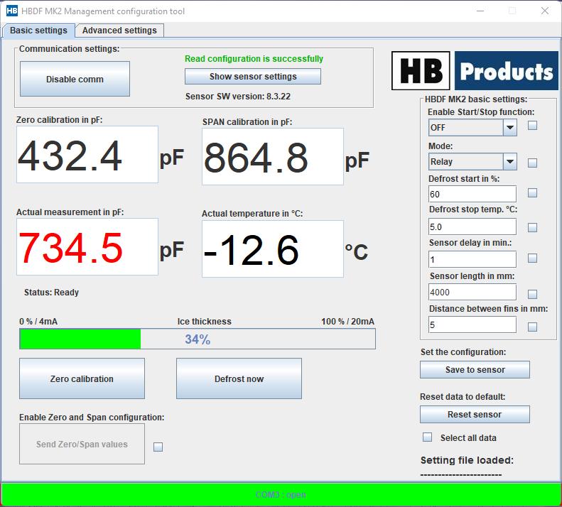
pF measurement is used to start and stop the defrost. The pF signal is measured continuously from ice build up and during defrost. Measurement of ice thickness depends on the calibration values, zero is the starting point and span is the sensitivity, both depend on sensor wire length as well as fin distance. During defrosting, the evaporator gets wet, thereby increasing the measured pF signal to maximum value ”MpV”, when the pF signal has fallen more than 60% then the defrost is stopped (indicating that all the ice has melted)
The signal output is a combination on analog 4-20mA and two digital relay outputs, shown on graphic chart below.
DEFROST
PLC Connection
Note: the surface is wet after defrost, the pF signal only drops to start value after the thin water film is frozen.

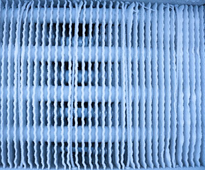
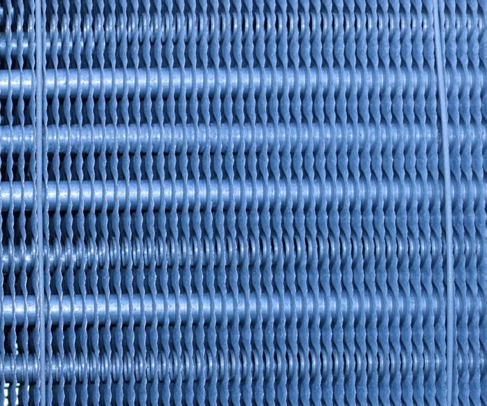
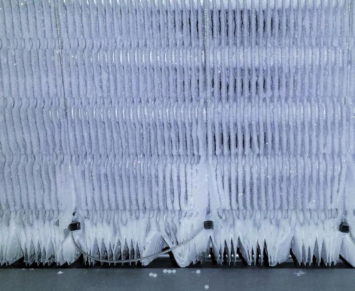
The best way to obtain an optimal defrosting is by use of Defrost on Demand sensor solution from HB Products. The pictures to the left shows 3 typical stages of ice formation on an evaporator.
3. Too much ice formation significant reduction of performance
1. Clean evaporator
Conditions are very different to traditionally refrigeration systems as the evaporators are installed outdoor in all weather conditions
The use of Heat Pumps as an environmentally friendly alternative to fossil fueled based heating has grown immensely.
DEFROST
1. Clean evaporator right after end of defrosting cycle
Tough Conditions
Especially defrosting is essential to gain optimal operation of a air-to-water heat pump. As the humidity in the surrounding air varies in relation to season and actual weather the interval between defrosting must vary as well.
2. Recommonded ice formation
3. Too much ice formation
By use of Defrost on Demand solution from HB Products stage 2 will be possible to maintain no mat ter which time of the year or actual weather condition. Beside it reduces the number of defrost cycles to what is needed it ensures optimal operation of the heat pump system, where timer based defrosting will demand defrost cycles when there is no need or it will allow the evaporator to clog with too much ice causing poor performance or no performance of the heat pump system.
2. Recommended ice formation before start of defrosting cycle
WE ANDUPTIME,INCREASESAFETYEFFICIENCY
We are dedicated to supplying switches and sensors for industrial applications. We focus on refrigeration, but our sensors can be used in other industrial applications where robust and reliable sensors are called for. Our sensors are developed and manufactured in Denmark. We mainly use local sourced parts to increase flexibility and reduce lead times. All sensors and switches comply with EU directives and have earned the CE marking. DF-HB2022-V1
All our products are developed and made in Denmark to ensure the highest standards of quality. We use local components widely in the production and have our own in-house Q&A to ensure that every item lives up to the highest standards.
DEFROST
Proven by the Industry
HB Products has made reliable and efficient sensors and switches for the cooling industry for over 25 years. We know that refrigeration systems must remain up and running, and we make all our products with that requirement in mind. Therefore, we test new products in refrigeration systems or industrial applications before we add them to our product line. That way we can guarantee that your installation will run safely and efficiently.
HB Products A/S Bøgekildevej 21 DK-8361 Hasselager Phone +45 87476200 www.hbproducts.dk