10 minute read
A LAYMAN’S GUIDE TO ULTRASONIC INSPECTION
Non-destructive testing (NDT) is a large and increasingly multifaceted discipline, encompassing a wide range of techniques such as magnetic particle inspection, radiography, ultrasonic testing, eddy current testing and more. As of the end of 2020, Ultrasonic Testing (UT) was the most commonly used method, accounting for 27%1 of the total NDT equipment market share. In this article you’ll fi nd a brief overview of the history, fundamentals, and current capabilities of UT as a technique.


A Short History of Ultrasonic Testing


Ultrasonic testing’s roots can be traced back to the classic ‘tap test’ of historical blacksmiths and metalworkers. In these tap tests, an experienced craftsman would give test pieces a firm whack with a hard object, such as a hammer or coin, and then listen for the resulting ring to tell whether or not the object was ‘sound’ from the sharpness, tone and other sonic qualities of the produced noise. While this is a long way practically from the scientific approach of modern UT, the concept of utilising sound to test materials was the driving constant throughout its subsequent development. The development of modern ultrasonics really got underway in the 1940s and 50s, with a marked acceleration in sophistication following the electronic revolution at the tail end of WW2.
In 1945 Floyd Firestone, an American physicist specialising in acoustics, patented a device built from modified RADAR instruments called ‘The Supersonic Reflectoscope’2 which he described as ‘a means of inspecting the interior of solid parts for flaws’. The Reflectoscope operated in a ‘pulse-echo’ configuration using a single quartz crystal search unit which both sent and received, which was notable in comparison to his contemporaries who made use of separate sending and receiving units. The search unit emitted a 2.25MHz ultrasonic pulse into materials and then plotted the amplitude of returning echoes against time on an oscilloscope screen, making the Reflectoscope arguably the world’s first A-Scan flaw detector.
Firestone’s invention was a breakthrough moment for the field of ultrasonic testing, but it would take a number of years and a lot of innovative industrial design before UT developed into the mature and reliable inspection technique it’s considered to be today. For this to happen, certain technologies needed to be pioneered first, such as the discovery of high-power composite crystals to replace quartz or digital electronics to replace the analogue valve based oscilloscope systems used in the 40s.
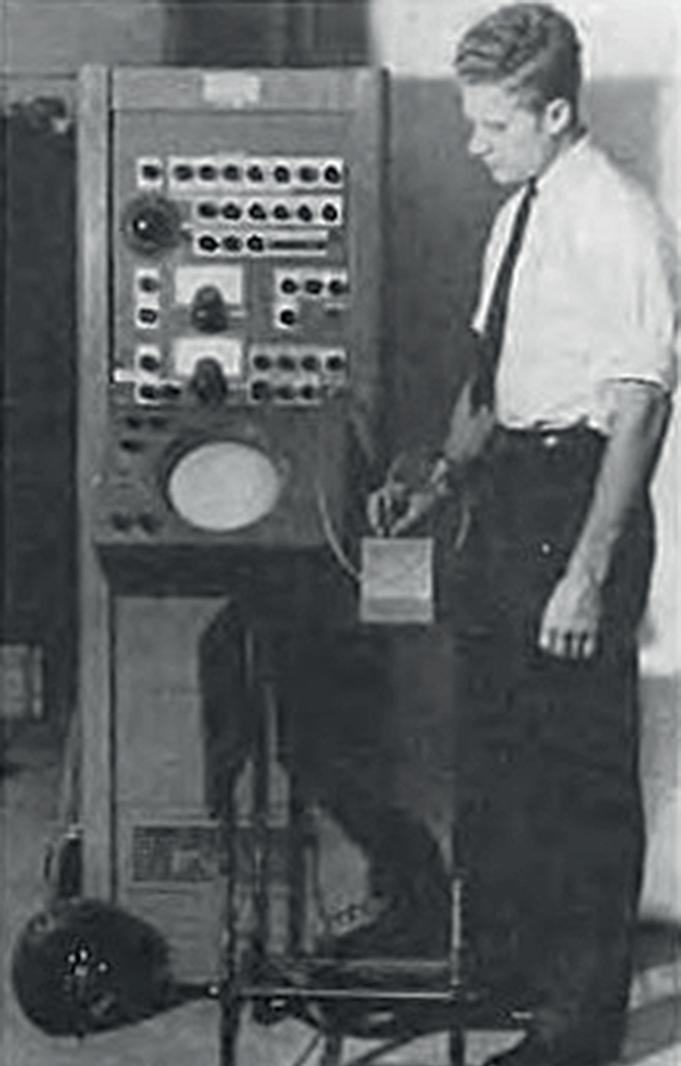
Floyd Firestone with his A-Type Supersonic Refl ectoscope What is Ultrasound?


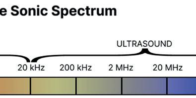

Fundamentally, sound is just the name for a type of mechanical wave that travels through solids, liquids and gases by making their particles oscillate, or vibrate, between 20 and 20,000 times a second (Hz). Because this frequency region is what the human ear evolved to detect, it is also known as audible sound. Ultrasound, therefore, refers to the region of frequencies that are too high, i.e. that vibrate too fast, to be detected by the human ear. Conversely, Infrasound is the range of frequencies that are too low to be detected by the human ear. The waves used for non-destructive testing are extremely high pitched when compared to the audible range. The lowest commonly used frequency is around 1 MHz (1 million Hz), which is fifty times higher than the highest sound you’ll ever hear. For specialist applications like scanning acoustic microscopy the frequencies employed can go all the way up to a staggering 2,000 MHz3! The important trade-off engineers consider when it comes to their choice of ultrasonic frequency is penetration vs. resolution; as ultrasonic waves increase in frequency they can be used to make out much smaller features within a material, but will lose much of their ability to penetrate deep into them. Conversely, lower frequency ultrasound will have a much easier time penetrating material, but have much lower resolving power. The most commonly used frequencies within industrial testing sit within the 0.5MHz to 20MHz range. The bottom end of the range is employed when testing composites and highly attenuative polymers while the top end is more useful for very thin metals and high-precision applications like bolt tension measuring.
How Does Ultrasonic Testing Work?
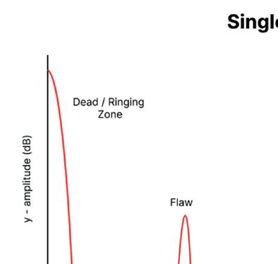
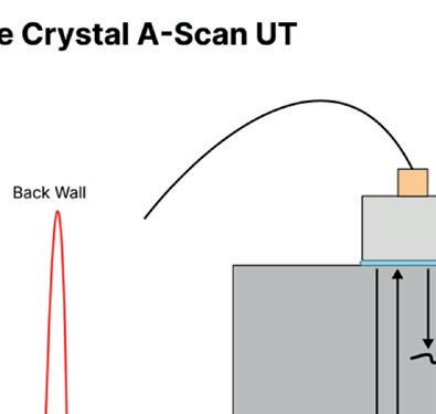
On a conceptual level, ultrasonic testing is a fairly intuitive technique to understand and requires little abstraction or higher level understanding. An ultrasonic pulse is generated by a transducer which is acoustically coupled to the test piece. This ultrasonic pulse travels into the material, reflecting back to the transducer whenever it hits a boundary, such as an air bubble, crack or the back surface of the piece. The strength of these reflections and how long it took for them to come back are measured and then plotted on a 2D display. The explanation and diagram above are descriptive of a specific type of ultrasonic inspection, in NDT jargon this is known as a ‘0° Single-Crystal A-Scan inspection’. ‘0°’ refers to the angle that the transducer is offset from the surface, ‘single-crystal’ refers to the specific construction of the transducer and ‘A-Scan’ refers to the way the results are displayed and interpreted. This type of inspection is the classic interpretation of UT and more or less the same setup pioneered by Firestone. However, as the field has developed, so too have the methods employed by inspectors. As more powerful piezoelectric composites, the crystals that produce the ultrasound, began to see use, it became feasible to transmit the ultrasound into materials at an angle, allowing for the fusion face of welds to be inspected without radiography. Advances in transducer design and computing power saw the production of transducers with more than one piezoelectric crystal inside, leading to the development of dual crystal transducers for near surface inspection and eventually to the introduction of phased array ultrasonics in the 1980s, where 12 or more individually fired crystals could be connected to one another. Increases in computing power also lead to different ways of displaying UT information, such as C-Scans and S-Scans, providing inspectors with much more easily interpretable results.
A-Scan displays are interpreted based on an understanding of the part’s geometry.
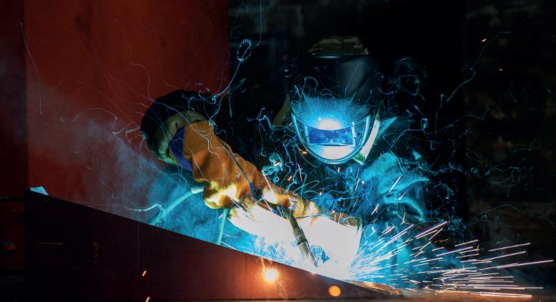
Weld testing makes up a large proportion of the global ultrasonic testing market (Picture credit: loda.gov.ua, CC BY-SA 4.0, via Wikimedia Commons)
Where is Ultrasonic Testing Used?
UT makes up over a quarter of the total NDT market, and has achieved supremacy mainly as a result of its versatility as a technique with new developments continuously adding capabilities to a UT inspector’s arsenal. While earlier designs were limited to volumetric inspections of metals below a certain thickness, the current suite of options available to ultrasonic inspectors are very comprehensive. They include detection of surface flaws, measurement of coating thickness on non-metallic substrates, automatic full-body immersion scans of complex parts and some guided wave technologies even allow for long-range ultrasonic inspection of pipelines up to 90m4 away from the transducer. As a result of this versatility, and in combination with its high accuracy, UT is employed in some form in an overwhelming majority of high-tech industries. The top users by size are the oil & gas sector, aerospace industry and the utility & power sector. Within these sectors the most common use cases are often weld testing: the thorough scanning of welds to check for manufacturing defects, and corrosion monitoring: the periodic inspection of pipes & plates to check their rate of corrosive decay over time.
What Does the Future of Ultrasonic Testing Look Like?
One of the downsides of current UT methods is that even a basic A-Scan operator must be rigorously trained to be able to properly perform an inspection; in 2018 a Level 1 NDT technician in the US earned a median salary of $73,000 – about 40% higher than the median US salary across all occupations5. This is exacerbated by a general skills shortage within NDT as a whole that sees demand for operators outpacing supply. There are two trends developing as businesses attempt to reconcile the expense of NDT with its absolute indispensability; increasing demand for low-cost, low-training UT solutions and a greater focus on automated UT systems. The former will most likely be achieved as manufacturers find ways to bring together the stunning images of advanced UT with the ease-of-use seen from traditional techniques like thickness measurement. The latter is already subject to frenzied development, and the last few years have seen autonomous drones and crawlers perform jobs in hours that may have taken multiple operators days to complete.
Elcometer NDT Equipment

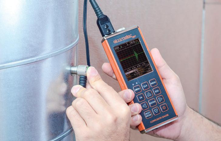
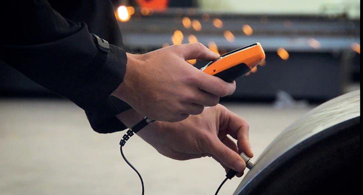
Elcometer NDT specialise in the manufacture of portable, user-friendly and highly robust ultrasonic equipment for the UT market. The comprehensive range of gauges represent exceptional value for money, without compromising on the features or build quality required by inspectors. For less involved applications, such as to test for uniform corrosion or to take coating thickness measurements on non-metallic substrates, Elcometer have developed the MTG & PTG ranges (Material/Precision Thickness Gauge). These numerical thickness gauges are thoughtfully designed to make it much easier to perform common inspection types such as corrosion mapping or thickness checking and feature an easy-to-learn user interface, intelligent transducer recognition and automatic 1 or 2 point calibration. All inspection data gathered can then be rapidly uploaded via Bluetooth® into ElcoMaster® , our bespoke data management platform, for analysis and reporting. For more complex inspections, we manufacture a number of powerful A-Scan capable devices more suited to this type of work. The Corrosion Gauge, Precision Gauge and Flaw Detector ranges (CG, PG & FD respectively) provide A-Scan capability and tuned functionality in a tough, compact package. The Elcometer CG100ABDL+ is one of the most advanced thickness gauge solutions on the market, while the Elcometer FD700DL+ serves double duty as a thickness gauge and flaw detector geared towards angle scanning. For more information, contact us at: Email: sales@elcometer.com Visit: www.elcometer.com



1 Non-Destructive Testing Market Size, Share & COVID-19 Impact Analysis , By Technique (https://www. fortunebusinessinsights.com/non-destructive-testing-ndtmarket-103596)
2 The Supersonic Reflectoscope, an Instrument for Inspecting the Interior of Solid Parts by Means of Sound Waves, Floyd A. Firestone (The Journal of the Acoustical Society of America, January 1946)
3 Acoustic Microscopy (http://www.soest.hawaii.edu/ HIGP/Faculty/zinin/Zi-SAM.html)
4 Long Range Ultrasonic Testing (LRUT) – Alliance Inspection (https://www.allianceinspection.co.uk/ specialist-services/long-range-ultrasonic-testing/)
5 PQNDT Salary Survey 2018 (https://www.pqndt.com/ wp-content/uploads/2020/01/PQNDT-2018-SalarySurvey.pdf)


Elcometer CG100ABDL+ Elcometer MTG8DL


Call Nigel Bean for more information on +44 (0) 1442 826826 10 great reasons to exhibit at Surface World 2023
– Meet and connect with prospective customers – Strengthen your bond with existing customers – Learn about new developments in your industry – Meet new companies that can help your business – Close deals with new customers during the show – Strengthen or establish your brand – Learn what your competitors are doing right – Rapidly expand your database of sales leads – Speak directly to your target market – Optimise your sales and lead generation strategy


