Publisher’s Note: The information provided in this publication is for informational purposes only. While all efforts have been taken to ensure the technical accuracy of the material enclosed, Fluid Power Journal is not responsible for the availability, accuracy, currency, or reliability of any information, statement, opinion, or advice contained in a third party’s material. Fluid Power Journal will not be liable for any loss or damage caused by reliance on information obtained in this publication.
Celebrating 30 Years of Excellence in Fluid Power
By Paul Prass, Founder & Publisher, Fluid Power Journal
» DEAR READERS,
This issue marks a momentous occasion as we celebrate the 30th anniversary of the Fluid Power Journal, and it is our 300th edition!
Our journey began with the inaugural issue in January 1994. It was the brainchild of Jim Morgan, then Executive Director of the FPS, along with key members of the FPS Executive Committee, notably George Nordenholt, Fred Brown and I. We developed a vision to create a publication that would become a cornerstone for the fluid power industry.
Throughout 1993, we dedicated countless hours to refining the concept of a publication
that would deliver the most relevant and insightful news to our industry. The months leading up to our first issue were filled with excitement, purpose, and a fair share of trepidation. It was the unwavering support from numerous individuals and fluid power companies that turned this vision into reality.
We extend our deepest gratitude to everyone who has contributed to and supported the Fluid Power Journal on behalf of the International Fluid Power Society (IFPS). Your dedication has been instrumental in our success.
Like any worthwhile endeavor, our journey has not been without its challenges. We owe special thanks to Dave Prevalet and John Groot, who went above and beyond to support both the publication and the society.
A heartfelt thank you to our tireless team, who work diligently to bring you the Fluid Power Journal in print and online each month: Hannah, Bob, Nick, Mike, Dan, and Lauren. Your efforts are the backbone of our success.
We are honored to serve you, our readers. Your engagement and support have been the driving force behind our achievements over the last 30 years.
Please enjoy the Fluid Power Journal timeline on page 28, and a special thank you to our year-to-date 2024 advertisers on page 36 & 37!
A special thank you to the Journal Oversight Committee:
• Chauntelle Baughman, OneHydraulics Inc.
• Tom Blansett, IFPS
• Brian Dittmer, IMI Precision Engineering
• Dan Helgerson, FPJ Technical Editor
• Jeff Hodges, Altec Industries, Inc.
• Garrett Hoisington, Open Loop Energy
• Donna Pollander, IFPS
• Scott Sardina, Waterclock Engineering
• Bradley (BJ) Wagner, IFPS
The fluid power industry is undergoing a transformative phase, driven by digitalization, energy efficiency, sustainability, material and manufacturing advancements, and electronic monitoring and controls. We hope that the Fluid Power Journal can play a significant role in helping manufacturers and end-users navigate these trends. Our focus will be on enhancing efficiency, reducing environmental impact, and improving safety and reliability. Embracing these technologies will be crucial for staying competitive in a rapidly evolving market.
We believe the future of fluid power is not just about moving fluids and air; it's about moving towards a smarter, more efficient, greener, and connected world. Our goal is to continue producing the best industry trade journal in print and online, month after month.
Thank you to our readers, advertisers, supporters, and the International Fluid Power Society for your continued support. Here's to another 30 years of success and innovation!
Sincerely,
Paul Prass Publisher, Fluid Power Journal PPrass@FluidPowerJournal.com
Bruce Bowe, CFPAI/AJPP - Altec Industries, Inc. Cary Boozer, PE, CFPE - Motion Industries, Inc.
Ethan Stuart, CFPS, CFPECS - Quadrogen Power Systems
Jon Rhodes, CFPAI, CFPS, CFPECS - CFC Industrial Training
Stephen Blazer, CFPE, CFPS - Altec Industries, Inc.
Wade Lowe, CFPS - Hydraquip Distribution, Inc.
Jeff Curlee, CFPE, Cross Mobile Systems Integration Deepak Kadamanahalli, CFPS - CNH Industrial Steven Downey, CFPAI/AJPP - Hydraulex John Juhasz, CFPS - Kraft Fluid Systems
CHIEF EXECUTIVE OFFICER (EX-OFFICIO) Donna Pollander, ACA
Fluid Power Journal (ISSN# 1073-7898) is the official publication of the International Fluid Power Society published monthly with four supplemental issues, including a Systems Integrator Directory, Off-Highway Suppliers Directory, Tech Directory, and Manufacturers Directory, by Innovative Designs & Publishing, Inc., 3245 Freemansburg Avenue, Palmer, PA 18045-7118. All Rights Reserved. Reproduction in whole or in part of any material in this publication is acceptable with credit. Publishers assume no liability for any information published. We reserve the right to accept or reject all advertising material and will not guarantee the return or safety of unsolicited art, photographs, or manuscripts.
NEW PROBLEM Multi Pressure Press Pump Exploded
By Robert Sheaf, CFPAI/AJPP, CFPE, CFPS, CFPECS, CFPMT, CFPMIP, CFPMMH, CFPMIH, CFPMM, CFC Industrial Training
» THE ATTACHED CIRCUIT on an older 75-ton press worked well for years. The vane pump had a 105 GPM output driving an 8″ bore cylinder with a 5½″ rod. They produced three distinctive designs of formed hi-strength plates for truck side panels. The plates reduced the damage that occurred during an accident. The force needed for each plate varied so the designer of the hydraulic system used a solenoid-controlled tri-pressure relief valve with unloading valve 2B for idle conditions.
A problem developed with the 3-position directional valve that controlled the tri-pressure relief. Its spool was worn to the point that they could not get the maximum pressure of 3000 PSI. But the 1000 and 2000 PSI worked well. They found a different brand valve in stock that had the same 3-position tandem center port setup and they concluded that it should work fine.
When they started up the system and shifted the valve manually with a Phillips screwdriver, the pump blew one side out. Luckily, no one was hurt.
What did they do to cause this problem?
For the solution, see page 38.
Robert Sheaf has more than 45 years troubleshooting, training, and consulting in the fluid power field. Email rjsheaf@cfc-solar.com or visit his website at www.cfcindustrialtraining.com. Visit fluidpowerjournal.com/figure-it-out to view previous problems.
FROM CHAL lENGE TO SOLUTION
The Impact of Advanced Valve Technology on Medical Technology
By Todd Harmon, Vice President of Canfield Industries Spartan Scientific (Division of Canfield Industries), APVS-08 Valve on Medical Technology
Moreover, the integration of sophisticated air piloted control mechanisms allows for precise management of fluid flow, which is crucial for the meticulous cleaning processes required in medical applications. These valves are designed to be configurable, with options for normally closed, normally open, or double acting positions, thereby offering flexibility to meet various operational needs. The addition of optional sensors and manual overrides further enhances functionality, enabling real-time monitoring and control adjustments during operation.
The impact of these advancements extends beyond individual components to the overall efficiency and cost-effectiveness of medical equipment. For example, the new valves have demonstrated their reliability through comprehensive testing, showing significant cost savings by reducing maintenance needs and prolonging the lifespan of cleaning machines' critical components. These improvements have led customers to transition entirely to the new valves, resulting in increased orders and an enhanced market presence for the distributors. As the industry moves forward, such advancements set new benchmarks for what is achievable, ensuring that medical equipment can operate with greater reliability, efficiency, and safety.
FLUID CONTROL
TECHNOLOGY
drop-in replacement for the previous units, but with a more precise design and increased functionality. The new valve is a media-separated, air-piloted control valve adept at managing the caustic and challenging fluids used in medical cleaning applications. It features CPVC bodies and diaphragms made from advanced materials such as FKM, NBR, EPDM, and PTFE. This ensures compatibility with aggressive cleaning agents while offering the necessary performance.
HOW THE VALVE WORKS
The valve operates using a sophisticated air-piloted control mechanism, allowing for precise management of fluid flow. It is designed as a 2-way, 2-position valve that can be configured to be normally closed, normally open, or double-acting. This flexibility is crucial as it allows the valve to be adapted for various specific applications, ensuring optimal performance in each scenario. This mechanism ensures that the valve responds accurately to varying operational demands, making it ideal for critical applications such as endoscope cleaning machines. The valve uses an inert gas or spring mechanism to control its operation. The addition of optional sensors and manual overrides enhances its functionality, allowing for real-time monitoring and control adjustments during operation.
PLAYS A CRUCIAL ROLE IN MEDICAL APPLICATIONS WHERE PRECISION AND RELIABILITY ARE ESSENTIAL.
THE NEED FOR A NEW SOLUTION
Endoscope cleaning is a process that requires meticulous attention to detail and reliability in the operation of cleaning equipment. One long-standing customer faced significant operational challenges with the performance and cost of their previous valve supplier. The supplier's valves were integral to the cleaning machines, yet this customer found them failing to meet the necessary standards of quality and efficiency, leading to increased operational downtimes and maintenance costs.
In response to this customer's needs, a design team initiated the development of a new valve. This product was designed as a
valve can be operated manually in case of automated system failure or during maintenance procedures.
Overall, these advanced features contribute to the valve's reliability and versatility. By enabling precise fluid control, real-time monitoring, and adaptable configurations, this valve addresses the stringent requirements of medical equipment, ensuring both operational efficiency and patient safety. The integration of such advanced technology in valve design sets a new standard in the industry, pushing the boundaries of what is possible in fluid control applications.
To control its operation, the valve employs either an inert gas or a spring mechanism. The use of an inert gas helps to prevent contamination and maintain the integrity of the system, which is especially important in medical applications where cleanliness is paramount. The spring mechanism, on the other hand, provides a reliable and consistent force to operate the valve, ensuring smooth and predictable performance.
Furthermore, the valve's design includes the capability to integrate optional sensors and manual overrides. These additions significantly enhance the valve's functionality by allowing for real-time monitoring and control adjustments during operation. The sensors can provide critical feedback on the valve's status, such as position and flow rate, enabling operators to make informed decisions quickly. Manual overrides offer an additional layer of control, ensuring that the
FLUID CONTROL FOR MEDICAL TECHNOLOGY
Fluid control technology plays a crucial role in medical applications where precision and reliability are essential. Endoscope cleaning machines, as well as other devices such as dialysis equipment, and automated medication delivery systems rely heavily on accurate fluid control to ensure patient safety and the effectiveness of treatments. Advanced valves and control mechanisms are necessary to manage various fluids, including aggressive chemicals and sensitive biological materials, without contamination or failure.
CURRENT STATE OF THE INDUSTRY
The medical technology industry is continually evolving, with increasing demands for higher precision, reliability, and efficiency.
continued on page 08
IMPORTANCE OF VALVES IN MEDICAL APPLICATIONS
REGULATORY CONSIDERATIONS IN FLUID CONTROL FOR MEDICAL TECHNOLOGY
THE IMPACT OF THE NEW VALVE
CONCLUSION FUTURE TRENDS IN FLUID CONTROL TECHNOLOGY
THE FUTURE OF FLUID CONTROL TECHNOLOGY IN MEDICAL APPLICATIONS LOOKS PROMISING, WITH INNOVATIONS ON THE HORIZON THAT COULD FURTHER ENHANCE PRECISION AND EFFICIENCY.
PUSHING THE INDUSTRY FORWARD
Lubriplate’s complete line of ultra high-performance, hydraulic fluids has been designed to provide a wide range of benefits including: extended fluid change intervals, cooler operating temperatures, reduced friction and reduced downtime. Products include...
•Designed for environmentally sensitive industrial and marine applications.
• Meets U.S. EPA Vessel General Permit (VGP) Requirements. Readily biodegradable.
•Does not leave a sheen on the water.
REPLACING SEALS ON VALVES
Three-way and four-way mobile hydraulic multi-spool directional control valves are available as one-piece units, consisting of a single casting with multiple spools, and as modular units, consisting of multiple segments held together with through bolts. Segmented valves are commonly called "stack valves" or a "valve bank." There are seals at the fittings and on the spools where they protrude
from the valve body. There are also seals between the segments of a valve bank. High temperature can make the seals brittle and is the primary cause of seal failure on fittings and between valve segments. Temperature affects spool seals as well, but they can also fail due to over-pressure in the return line and/or contamination on the spool as it slides in and out of the valve body. When spool seals
fail, fluid will be seen coming from around the spool behind the handle or from the bonnet that covers the spring chamber at the back. Fittings and valve segments commonly use O-ring seals. The spool seals may be O-rings or square-cut rings. The seals may be in SAE, British, or metric sizes. When replacing the seals, it is important that the replacement seals be the same durometer (hardness) as
the original seal. Verify that the material of the seal is also the same. Due to the high operating temperature of some mobile hydraulic systems, Viton® seals may be used instead of the traditional Buna material.
Safety Tip: Never use your hands to check for leaks; always use a piece of cardboard or wood. High-pressure leaks can cause fluid-injection injuries, resulting in amputation or death.
Special function valves incorporated into a valve segment or bank, like the pressure relief and load check, use an O-ring boss seal. The seals on the diameter of the cartridge may have a back-up ring of nylon or Teflon® in addition to the O-ring. It is crucial that the replacement back-up ring be re-installed on the correct side of the O-ring. If possible, it is best to use a seal kit supplied by the manufacturer to prevent using the wrong-size seals. Work-port relief valves may vary in their pressure settings from one valve segment to another. When removing these function cartridges from a multi-section valve bank, ensure they are marked to prevent them from being installed in the wrong cavities after the seals are replaced.
It is sometimes difficult to identify the source of the leak in a valve bank because the leak attracts dust and dirt that both cover up and spread the oil stain. If the leak is so substantial that it washes down the side of the valve, then tracing the clean path will lead to the leak. Because there may be more than one leak, it is recommended that the whole valve be cleaned and then wiped dry before cycling the machine to observe the oil leak. Once the leak(s) has been identified, the decision must be made whether to change all the seals. It may be practical to change just the leaking seals at fittings, line connections, and cartridges. If the valve is leaking between the segments, or if the segments are separated, the seals between all the segments should be replaced. Sectional valves may have multiple diameter and thickness O-rings between the sections. When re-assembling the valve, place the valve on a flat surface. While tightening the bolts or studs holding the valve sections together, ensure they are torqued to the specified value in the proper sequence. If possible, actuate the spools while torquing the bolts to ensure the spools are not binding. The mounting points should remain flat on the surface.
Working Segments Outlet Segment
Inlet Segment
(Equipped with pilot-operated relief valve)
Fig. 3.29 Multi-Spool Directional Control Valve Seals
When replacing multi-section valves, confirm the mounting pads all contact the base before tightening the valve. If they don’t mount squarely, it may be an indication the mounting base has been warped or twisted, the valve was not assembled on a flat surface, or the valve was damaged in shipping. Using the mounting bolts to pull the valve-mounting pads to the base may put stress on the sections, causing one or more of the valve spools to bind.
Replacing single-spool seals in a valve like that shown in Fig. 3.29 is justified because the seals are easy to get to and because the valve does not have to be removed and dis-assembled. Moreover, downtime will be relatively short if one or two spool seals are replaced. This is an important consideration when the machine must be returned to service after routine maintenance.•
TEST YOUR SKILLS
1
2
What should the mechanic expect to find if there is a fluid leak from a stack valve like that shown in Fig. 3.29 where the spool protrudes to connect to the operating handle?
A. Bent valve spool.
B. Leaking spool seal.
C. Broken valve spool.
D. Stuck directional control valve.
E. Cylinder that drifts holding a load.
When replacing one valve section of a multi-section directional valve, it is necessary to:
A. Replace the seals between all the sections.
B. Replace the seals next to the section being replaced.
C. Replace the seals that fall out during the replacement process.
D. Replace the seals in the pressure pathway of the valve.
E. Replace the seals between sections that came apart during the replacement.
See page 38 for the solution.
SALARY SURVEY 2024
How old are you?
» IN AN EFFORT to combat the skills gap in fluid power and other industries, Fluid Power Journal, in collaboration with the International Fluid Power Society (IFPS), established an online salary survey in order to create a baseline resource for professionals. Thank you to the participants! Here are the results.
WHERE DO YOU LIVE?
42% HOLD AN IFPS CERTIFICATION
have you
High
Some
Associate's
Bachelor's
30.1% FEEL THAT IFPS CERTIFICATIONS IMPACT THEIR SALARY AND/OR JOB POSITION.
On average,
www.inserta.com | adaconn.com
Adaconn® + Inserta® offer a variety of components including flange adapters and connectors, ball valves, check valves, pressure controls, and modular fittings that can be used to make smartly designed compact hydraulic systems. A large inventory of finished components allows most standard items to ship from stock. Custom components and assemblies are available.
Visit our website to learn more about our expanding product offerings.
www.diamondhydraulics.com
Diamond Hydraulics is a veteran owned small business that manufactures, rebuilds, and repairs hydraulic equipment including cylinders, pumps, motors, valves, power units, and much more. We were established in 1999, and have over five decades of experience in hydraulic equipment repair.
Diamond Hydraulics provides quality workmanship, extensive industry knowledge, and fast turnaround time on repairs and replacements. All repairs are brought back up to OEM standards and tested with state-of-the-art test equipment.
www.hiipumps.com
No compromise on Quality and Performance
Founded in 1976 and based in Chatsworth, California, Hydraulics International, Inc. (HII) is a premier provider of pneumatically driven hydraulic pumps, portable and skid-mounted high-pressure hydrostatic test units, and accumulator charging units worldwide. From its inception, HII has prioritized innovative design and engineering, continuously advancing in the fluid power technology. Proudly made in the USA.
When reliability matters, trust the leader in high-pressure test pumps and gas boosters: HII.
/low-flow-experts
Measure low flows below 1-100 cc/min with 0.2% accuracy and response rates as low as 1.6 milliseconds. Because you value your flow, find value in the data from a Max Flow Meter. High resolution, high accuracy, bi-directional, and quadrature signal output options make Max Meters the choice in measuring low flows. Reach out to us today for pricing and availability.
www.essentracomponents.com
Essentra Components is a worldwide leader in the manufacturing of plastic protection products for the fluid power industry. Essentra’s cap and plug manufacturing capabilities in Erie, Pennsylvania are complemented by additional molding facilities in Flippin, Arkansas as well as international locations in Mexico, Costa Rica, and Brazil. Essentra also operates two warehouse and sales centers in Canada. With over 45,000 standard products available for immediate delivery and additional custom molding capabilities, Essentra is the expert at making the right product to meet your most demanding requirements.
Main’s website provides quick access to the 120 page catalog that includes popular styles of MAIN Manufacturing’s extensive offering of carbon and stainless Hydraulic Flanges and Components – ready for immediate shipment. Metric ordering information, weld specs, and dimensional information included. The “Quick Reference Guide” helps specify less popular items often stocked or quickly manufactured (generally 3-4 days) at our US plant. “Create-A-Flange” offers more parts than the catalog — by picture. If it’s not here, or for questions, E-mails may be sent to get your answer quickly. 1-800-521-7918 info@mainmfg.com
By Alan Wheatley, Motion Repair & Services
Wheatley is a MOtION Branch Manager and has over 35 years of fluid power industry experience.
1 Removing OEM-specific or obsolete components and replacing them with standard products with technical advantages.
2 Adding IIoT sensors to provide machine performance feedback for monitoring and predictive maintenance.
3 Installing contamination sensors, water sensors and improved filtration products to ensure fluid is kept in optimum condition.
4 Changing fixed-speed pump-motor assemblies to variable-speed versions to match flow and pressure output to machine demand (which can offer significant energy savings).
5 Upgrading electrical control systems to provide local and remote capabilities for fault diagnosis.
CONVERSION OF OEM COMPONENTS TO STANDARD PRODUCT
Over the years, many injection molding machine OEMs have used custom hydraulic components supplied by their preferred manufacturers. These OEMs work with hydraulic manufacturers to design components to their specific requirements that are frequently proprietary to the machine builder. While this helps the OEM in the aftermarket, this practice also limits competitive product options for users who purchase their machines. Users cannot buy the products direct from the hydraulic distribution channel and must go to the OEM for replacement parts, often at inflated cost. Additionally, continuing aftermarket parts support is reduced as the machine’s age will dictate if the OEM is willing to provide parts to the end user. Sometimes, customers need to go to the internet or surplus parts providers just to keep their machines running. Contacting a reputable technical fluid power distributor with experience in plastic machinery could yield recommendations on replacing the OEM-specific obsolete components with more readily available equivalents. Value-added technical distributors will look at the machine systematically and provide alternatives the user may not have considered. An example could be using proportional control valves instead of standard on/off valves or complete manifold assemblies for power, injection or clamp functions.
Converted manifolds (Figures 1-2) often utilize newer technology components, simplifying the circuit design while improving performance and reducing heat generation—which is wasted energy.
This conversion is for an injection manifold on an injection molding machine. Because the machine is obsolete, OEM parts and support are scarce. The conversion uses mostly standardized components with a simpler custom manifold solution designed by Motion, saving costs for the end user. Images courtesy of Motion.
continued on page 18
Figure 1 – Original Installation
Figure 2 – Upgraded Installation
MONITORING AND PREDICTIVE MAINTENANCE OPPORTUNITIES
Recent technology in IIoT sensors has given injection molding machine users real-time information on machine status to reduce unnecessary downtime. Unscheduled downtime of a high-production injection molding machine can significantly impact productivity and create scheduling headaches. IIoT sensors can provide continuous feedback on key machine parameters such as pressure, flow and temperature to confirm that all are within the recommended guidelines for optimum performance.
This information can be displayed locally or on a plant-wide dashboard on the user’s network. Maintenance and production personnel will be notified if a machine parameter is outside the recommended value, allowing the machine to be taken out of service before a catastrophic failure occurs. Additionally, continuous machine monitoring lets production managers predict when a machine may need to be removed from production for routine maintenance. Maintenance managers will be allowed to properly schedule machine service and ensure the required parts are available to complete the task in time.
FILTRATION SYSTEM INSTALLATION AND FLUID MONITORING FOR IMPROVED FLUID PERFORMANCE
An estimated 85% of hydraulic component and system failure is due to poor fluid quality. Most issues are related to contaminated fluid, but water content, elevated temperatures and machine fluid type are additional contributing factors to fluid health. Injection molding machines are high-pressure, high-speed and high-temperature applications. These extreme performance factors have an impact on fluid. How well the fluid is maintained likewise affects equipment performance. Many injection molding machines of the past did not provide proper filtration or temperature control. Additionally, recent fluids have had key additives removed to reduce environmental impact. This new formulation has made fluids more susceptible to varnish generation, leading to component malfunction, obstructions in heat exchangers and blockage in filter elements.
A crucial advance in fluid engineering is fluid sensors and high-performance filter elements that monitor and combat varnish generation in injection molding machines.
These sensors observe contamination and water saturation, plus provide real-time feedback on fluid-quality status. Ensuring the fluid is maintained within the recommended guidelines for the hydraulic system reduces unwanted costly downtime. As filter manufacturers better understand how these new fluids perform in these difficult applications, they update their filter element media and designs. The updates provide static-free elements that can counter the creation of varnish and other elements designed to remove varnish and free-standing water from the fluid. Adding these fluid sensors, filter elements and system upgrades can improve productivity.
VARIABLE-SPEED PUMP-MOTOR ASSEMBLIES TO MATCH FLOW AND PRESSURE TO MACHINE DEMAND
Most injection molding machines use various pump-motor assemblies to meet the hydraulic power demand of the machine cycle. These can be fixed-displacement or variable-volume pumps, or a combination
THE ABILITY TO REDUCE ENERGY COSTS ALLOWS THE FACILITY TO REDUCE ASSOCIATED GAS EMISSIONS BY AS MUCH AS 70%
of both. However, these pumps are typically connected to a fixed-speed electric motor, which runs at a constant speed regardless of duty cycle. Injection molding machines have dwell times during their machine cycle where the flow or pressure requirements change. These dwell times are an opportunity to introduce variable-speed pump-motor assemblies that will match the machine’s power demand, reducing energy consumption and CO2 emissions. Electrical power costs are always increasing, and the ability to reduce energy costs will benefit the facility’s bottom line in the long term. It also allows the facility to reduce its carbon footprint and impact on the planet, reducing associated gas emissions by as much as 70%.
Additional benefits of variable-speed solutions are lower noise, reduced cooling
requirements, simpler circuit design and connectivity to machine control systems. Lower noise levels could decrease the need for costly noise enclosures, while reduced energy losses may result in less water usage or removing heat exchangers altogether. Simpler circuit designs can be realized as the pump motor will vary the flow rate based on demand. The hydraulic circuit could allow users to remove costly proportional or servo valves and replace them with simpler on/off valving. As noted, changing the pump-motor assembly from fixed to variable speed could significantly improve the machine.
UPGRADED ELECTRICAL CONTROL SYSTEMS FOR IMPROVED PERFORMANCE AND REMOTE DIAGNOSIS
Electrical control systems are the brains behind injection molding machines. They control all the machines’ functions, including hydraulics, safety, barrel temperatures and speed control. Older machines have obsolete controls that make part replacement difficult or have limited control capabilities compared to newer versions. Additionally, some machine OEMs have proprietary control systems allowing only their technicians to access the program and service the machine.
Upgrading the electrical control system with off-the-shelf components with assistance from a qualified injection molding machine control specialist will minimize your dependency on OEM-specific parts and services. Having a control specialist upgrade the electrical system will give control back to the user to monitor and modify the machine’s performance to suit the specific application. Most new control systems are faster and more precise and allow remote access for troubleshooting and modifications by the specialist. Finding replacement parts will be easier using standardized products if failure occurs. Overall, upgrading your electrical control system is important to improving machine performance.
As older injection molding machines continue to operate as expected, there are many ways to upgrade them to improve performance and productivity. If the machine is mechanically sound, implementing these upgrades will improve performance and productivity and minimize unscheduled downtime. Engaging a third party with experience in this specialty can bolster your operation’s short- and long-term efficiencies. •
Digital Documents reverse-engineer systems cross/type components
Photo Navigation drilling down to individual components & parts
Interactive Prints illustrate machine operations & functions
Video Troubleshoot capture tribal knowledge & train on-the-job Can Work Offline on any device browser
Hydraulic and Pneumatic Industry Trends With NFPA
» THE LATEST DATA published by the National Fluid Power Association shows April 2024 total fluid power shipments decreasing -0.4% month over month and -0/4% year over year. 12/12 rates of change for total fluid power, hydraulic, and pneumatic shipments are all negative and trending downwards. The data and charts above are from NFPA’s Confidential Shipment Statistics (CSS) program where over 70 manufacturers of fluid power products report their monthly orders and shipments. More market information is available to NFPA members, allowing them to better understand trends and anticipate change in fluid power and the many customer markets it serves. Contact NFPA at 414-778-3344 for more info.
TOTAL FLUID POWER SHIPMENTS
INDEX DATA: 3 MONTH MOVING AVERAGE & 12 MONTH MOVING AVERAGE
This graph of index data is generated by the total dollar volume reported to NFPA by CSS participants. This graph uses moving averages to smooth out the data and clearly identify trends. (Base Year 2018 = 100).
SHIPMENTS: PNEUMATIC, MOBILE HYDRAULIC, AND INDUSTRIAL HYDRAULIC
INDEX DATA: 12/12 RATE OF CHANGE
Each point on this graph represents the most recent 12 months of shipments compared to the previous 12 months of shipments. For example, 7.3% (the August 2023 level of the pneumatic series) indicates that the value of pneumatic shipments from September 2022 to August 2023 were 7.3% higher than the value of pneumatic shipments from September 2021 to August 2022.
ORDERS: PNEUMATIC, MOBILE HYDRAULIC, AND INDUSTRIAL HYDRAULIC
INDEX DATA: 12/12 RATE OF CHANGE
Each point on this graph represents the most recent 12 months of orders compared to the previous 12 months of orders. For example, 8.5% (the August 2023 level of the industrial hydraulic series) indicates that the value of industrial hydraulic orders received from September 2022 to August 2023 were 8.5% higher than the value of industrial hydraulic orders received from September 2021 to August 2022.
TOTAL SHIPMENTS: SEPTEMBER 2023
This table shows various rates of change for the month of August 2023. Interpretation for each rate of change calculation:
M/M %: The percent change between the current month and the previous month.
Y/Y %: The percent change between the current month and the same month one year ago.
3/12 %: The percent change between the three most recent months and those same three months one year ago. 12/12 %: The percent change between the twelve most recent months and those same twelve months one year ago.
*Preliminary data subject to revision.
Pneumatic
The National Fluid Power Association’s Advanced Hydraulics Conference CONFIRMED for iVT EXPO USA
» JUNE 20, 2024 — The National Fluid Power Association (NFPA) is excited to announce its advanced hydraulics conference for off-highway vehicle and fluid power engineers at the upcoming iVT EXPO, taking place August 21-22, 2024, in Chicago, IL. This event, first held in the United States in 2022, is a premier exposition for the off-highway vehicle design and engineering community, featuring key technologies such as new powertrains, electric and hybrid systems, control systems, sensors, and autonomous technologies.
THE NFPA’S ADVANCED HYDRAULICS CONFERENCE WILL FEATURE A ROBUST LINEUP OF PRESENTATIONS BY INDUSTRY EXPERTS, ADDRESSING CUTTING-EDGE TOPICS SUCH AS:
• Improved Design & Control of Hydraulics on Electrified Off-Highway Vehicles
• Improved Hydraulic Performance Through Data Utilization
• Functional Safety Requirements for Hydraulic Systems
• Increase Hydraulic Efficiency for Longer Duty Cycles
• Improved Thermal Management of Electrified Vehicle Systems
Eric Lanke, NFPA President/CEO, stated, “NFPA member companies represent the cutting-edge technologies that vehicle engineers need to incorporate into their machine systems and designs. Their
participation as presenters in our education conference, combined with hands-on demonstrations on the iVT EXPO show floor, will provide a unique educational experience for our primary customers.”
Tony Robinson, Chairman of UKI Media & Events, organizers of iVT EXPO, commented, “We are honored to partner with the National Fluid Power Association of America. These are exciting times as electrification and automation drive and complicate the off-highway vehicle industry. This partnership offers a significant opportunity for experts in design and engineering to collaborate, and for member companies to participate as exhibitors.”
Registration for the conference is now open, including access to all educational sessions at iVT EXPO. The event will feature additional tracks on “Electrification, Hybrid and Alternative Fuel Sources” and “Autonomy, Cab Design and the Evolving Digital Interface.” This collaboration creates a must-attend event for off-highway vehicle and fluid power engineers. •
» For a full list of speakers, presentation details, and to register, visit iVT EXPO USA.
Discover the future of off-highway vehicles with the latest innovations from top global suppliers. See groundbreaking technologies, advanced components and new systems essential for powering the next generation of machinery
REGISTER NOW TO GET YOUR FREE CONTACTLESS EXHIBITION ENTRY PASS!
» IVT OFF-HIGHWAY VEHICLE TECHNOLOGY EXPO (iVT Expo), the international trade show dedicated to off-highway vehicle technology, is set to return for its highly anticipated North American edition. Scheduled to take place on August 21 & 22, 2024, at the Donald E. Stephens Convention Center in Chicago, this year’s expo promises to showcase a comprehensive display of the latest off-highway vehicle technologies, components and solutions from leading manufacturers and suppliers.
As the off-highway vehicle sector continues to evolve rapidly, iVT Expo serves as a platform where engineers and designers from OEMs and industry experts from around the world can come together, exchange ideas and explore the latest trends and technologies shaping the future of off-highway vehicles.
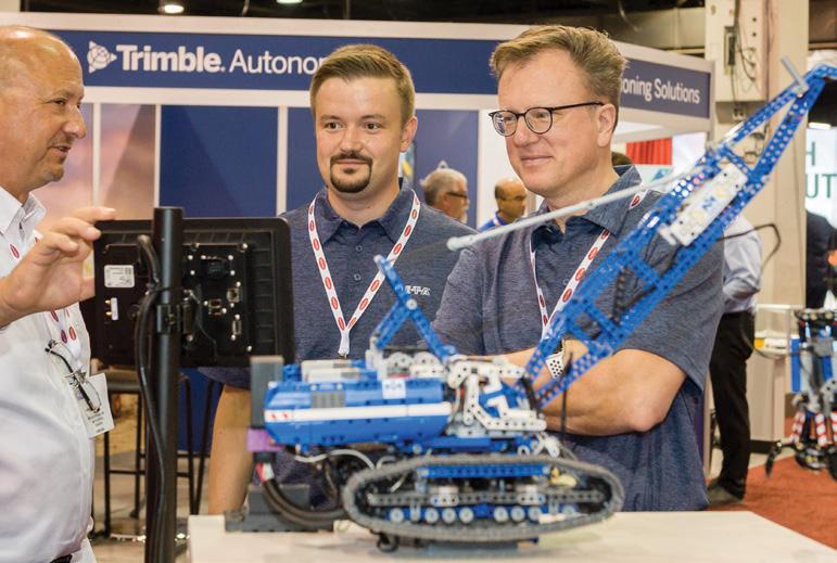
Attendees can expect an impressive line-up of 130+ exhibitors representing various sectors within the industry, including construction, mining, agriculture, material handling, forklifts and forestry. Exhibiting companies include Deere Electronics, Bosch Rexroth, Husco, Trimble, Bonfiglioli and Moog Construction.
The expo conference will feature more than 50 speakers from OEMs, policymakers, solution providers and academic institutions, across three tracks that explore key themes including electrification, digitalization, automation and sustainability. Parallel to the main conference, the National Fluid Power Association (NFPA) will present an advanced hydraulics conference on the latest advances in hydraulic technology.
"We are thrilled to welcome a prestigious line-up of exhibitors and speakers to this year's show in Chicago," said Ram Seira, event director. "Attendees will have the chance to connect with key figures in the industry, stay informed about emerging trends and uncover fresh business prospects – it’s a must-attend event.”
For more information about iVT Expo in Chicago, including registration details, please visit the show website ivtexpo.com/usa/en
A Vacuum Gripping Approach to Box Palletizing
The following is an opinion article written by Dane Spivak. Its intent is for conceptual purposes only. Contact Dane Spivak by email at dspivak@davasol.com.
Automated palletizing is a shared process among many manufacturing industries where cardboard boxes are picked, placed, and stacked onto pallets to be shipped or warehoused. Vacuum end effectors are often used on the robot arm as they provide a gripping force on the top of the boxes and offer an efficient cost-effective solution. The following article will focus on considerations for vacuum palletizing applications and how to effectively choose vacuum gripping tools. Before thinking about the gripping tool, it is best to first analyze the box(es) itself. The obvious required information to kick start the project includes the weight and dimensions. Additionally, all possible problematic box features should be understood. The points below may change the design of the vacuum system and tools to compensate for circumstances which are other than ideal.
• What is inside the box? Is it tightly packed or are there loose parts? Is the weight evenly distributed and centered or imbalanced?
• Are there any areas or features on the box which may impact the vacuum grip such as straps, gaps, or known imperfections?
• Is the cardboard corrugated or flat packed? Is it thick and sturdy, or thin and flexible? Is it porous or damaged?
• What is the quality and shape of the box? Is the box new or reused? Is it clean, dirty, tight, bubbled, floppy?
The above parameters are often mistakenly overshadowed by the box weight and dimensions. Most box sizes offer plenty of top surface area to provide substantial lifting forces and safety factors. The challenge is the box conditions, how to design a vacuum solution to
grip securely, and maintain a confident hold throughout the robotic transfer process.
Conceptually, the easiest box to grip is a lightweight, tightly packed, new box with high quality cardboard and a clean flat top. It requires little gripping force, is stable on its own, and provides a surface for easy vacuum cup sealing with little clogging or filtration issues. This theoretical box would require a few cups and a relatively low flow vacuum pump or venturi to get the job done. However, real world industrial environments rarely offer such opportunities. Because of that, in many applications, the top surface area of the box would be mostly covered by vacuum cups to offer a sturdy and balanced gripping force. Or in other words, the footprint of the vacuum tool would cover nearly the whole box as shown in Figure1.
With a vane pump or venturi, theoretical calculations could suggest the gripping force is overkill. But widespread multiple points of contact across the box is often necessary since the box contents may be unstable, the box itself could sway during movement, or the top surface could deform too much and “bubble”. All these factors could result in instability and cause the vacuum cup grip to peel off and drop the box.
The vacuum cup style and diameter are critical to providing a good seal which does not break. Typically, a single or multiple bellows soft cup is used with a diameter between 1” to 2” as shown in Figure2. These cups offer height and angular compensation and provide cup lip flexibility to conform to
the corrugated cardboard surfaces. The cup diameter range is a sweet spot to grip corrugated cardboard well without causing box deformation. Larger cups may initially grip the box well, but, during the lift or transfer the cardboard can deform and cause the cup seal to break and drop the box. Technically, cup diameters smaller than 1” would do the job well too, but it is unnecessary to deal with any more cups than what is needed as more parts can mean more problems and possibly larger pump requirements.
Foam vacuum pads can also be used for box palletizing applications as shown in Figure3. The advantage of foam is that it has sponge-like characteristics that allow for good deformation and sealing against corrugated cardboard. It can prove to be advantageous if the box condition is particularly poor and cup sealing is inadequate. However, foam wears out much more often than rubber suction cups, requires frequent replacement, and damage to one area requires replacing the entire foam pad.
3 – Foam vacuum pads
Whether it is intentional or not, vacuum cups may not seal against a box, or miss it entirely if multiple box sizes are being picked up. This can happen for a variety of reasons including box gaps, straps, tape, or damage for example. Cups not sealing can cause air to get sucked into the vacuum system which reduces the vacuum level pressure and therefore reduces the gripping
Figure 1 – Vacuum gripping tool box coverage
Figure 2 – Single and multiple bellows 2” diameter vacuum cups
Figure
force. Unwanted leakage can be controlled or prevented, which is typically done in two ways.
Figure4 shows a cup fitting with an orifice screw inserted. The purpose of the orifice screw is to restrict air flow (leakage) into the vacuum system. Figure4 demonstrates the use of an orifice screw to reduce the fitting diameter though some fittings or tools may have pre-built in orifice sizes for restricting flows. The smallest area or diameter where air passes through controls the maximum volume of air flow entering the vacuum system. Therefore, it is ideal to downsize the restrictive diameter as small as possible to limit unwanted leakage. However, the restrictive orifice should not be infinitely small since flow is required to create a seal for the vacuum cups. Additionally, the orifice should be large enough to allow debris, water, and dust to pass through and collect inside the inline vacuum filter instead of clogging the vacuum line. With that said, the common restrictive orifice diameters are around 1mm to 2mm.
Figure4 illustrates a typical application for using vacuum cups with orifice screws. Cups #1 and #2 are not sealed against the product. The installation of an orifice screw in the cup fittings minimizes leakage and allows a secure grip of the product using cups #3 and #4. It is important to understand the worst-case scenario to allow proper sizing of the vacuum pump or venturi. The tool design and pump sizing heavily rely on the situation where the most cups are exposed to leakage and relatively lower vacuum levels as a result.
Figure5 shows self-closing valves connected to four vacuum cups with a common venturi as a vacuum source. The vacuum cups, #1 and #2 are not sealed against the box being handled. When vacuum is applied, the self-closing valves on cups #1 and #2 experience an in rush of atmospheric air which closes the valves, isolating these cups from the common system. Cups #3 and #4 are sealed against the box. When the vacuum is turned on, the volume
of sealed air between the self-closing valve and the cup face is not large enough to close the valve. Therefore, the self-closing valves remain open allowing vacuum grip against the box surface. When vacuum is turned off, cups #3 and #4 release the box. The self-closing valves attached to cups #1 and #2 return to their open rest position, ready for the next cycle start.
There are different designs for self-closing valves and comparable performing components. Certain designs allow for the bottom seat of the self-closing valve to be adjustable. This feature controls how much flow it takes to close the valve, or in other words, its sensitivity can be adjusted based on the spring tension allowing it to be more versatile. Figure6 illustrates this concept. Other models have no spring at all, and essentially have a free-floating ball. There are also models that use a flexible rubber flap instead of a ball.
Zoning tools can make a major impact on the vacuum system capabilities and pump sizing. Zoning becomes increasingly important when gripping various box sizes or gripping more than one box at a time. Figure7 shows a twozone tool that grips one or two boxes at a time. Both zones turn on vacuum when gripping two boxes while only one zone turns on when gripping a single box. This allows for high vacuum levels and gripping forces to be achieved when gripping a single box without
the use of self-closing valves or orifice screws, which would also typically requires larger pumps. Additionally, if venturis are used on each zone it allows for energy savings as only half the compressed air is being used.
Vacuum pump or venturi sizing can be tricky as it heavily depends on the box condition, vacuum cup size and model, and use of self-closing valves or restrictive orifices. A good rule of thumb is to use a minimum of 1CFM of vacuum flow per 1” to 2” cup, or orifice. This is highly subjective based on the application and vacuum solution. In-house testing can certainly help determine vacuum level and flow requirements, but it is best to seek professional advice from experts and/ or the vacuum tool manufacturer to ensure that the correct vacuum source and size is selected. Popular choices for vacuum sources include vane pumps, venturis, and regenerative blowers. Vane pumps and venturis offer high maximum vacuum levels which are attractive with good sealing cups and minimal leakage. Blowers, despite having a relatively lower vacuum level, are chosen when significant leakage is present or for a larger vacuum system as they provide more vacuum flow while using less energy.
Vacuum palletizing applications can require attention to detail and critical thinking. But with a solid foundation they prove to offer excellent reliability and repeatability. When considering a vacuum palletizing solution, it is important to consider the box itself, its content, vacuum cup models, leakage flow reduction or prevention, zoning, and vacuum pump sizing. By prioritizing these elements, businesses can optimize their vacuum palletizing applications efficiently to meet the demands of the present-day industrial expectations. •
Figure 4 – Orifice screw threaded into a cup assembly and tool
Figure 5 – Self-closing valve tool demonstration
Figure 6 – Adjustable self-closing valve 3D cutaway
Figure 7 – Two-zone vacuum tool gripping one or two boxes
By Dan Helgerson, Technical Editor, Fluid Power Journal
It’s probably the case that a high percentage of those reading this article have designed or installed a fluid power system that used restrictive flow controls. And I would venture a guess that only a small percentage of you thought that using a flow control wasted energy.
After reading this article, you may never again specify or install a flow control without a twinge of guilt, reminding you that you are wasting energy.
I am not suggesting that we eliminate flow control altogether. One of the beauties of fluid power is that we can regulate the speed of linear and rotary functions from a single power source. This requires some type of flow modulation. What concerns me is that we consider the energy consumed by the control as part of the cost of using fluid power, and we don’t take into consideration the impact of our choices on the industry and the cost of operation.
energy must be used for work, or it becomes wasted energy.
Pneumatics and hydraulics have significant differences in the way energy is lost when using restrictive flow controls. The pneu-
I am not suggesting that we eliminate flow control altogether.
matic loss is more subtle and often more expensive than with hydraulics. You are not likely to burn your hand on a pneumatic needle valve, but I’ve seen the paint burn off a flow control in a hydraulic system.
the fluid with energy and then store it in a receiver for future use. When we waste hydraulic energy, it immediately turns to heat, and we have to deal with it. When we squander our stash of stored air molecules, it can go unnoticed.
I was once invited into a manufacturing facility where they make threaded brass parts. They have a number of pneumatic presses that secure a ferrule into a fitting. The press operators used to place the ferrule into the fitting and quickly move their fingers out of the way while they activated the press. As a safety measure, the company decided to use a horizontally mounted air cylinder to slide the ferrules into place, preventing the operators from endangering their appendages.
To move a ferrule requires a force of 0.56N (2 ounces). Someone (I am hoping it was not a fluid power professional) had selected cylinders having 50mm (2”) bores to push the ferrules into position. There were directional
There is no such thing as an energy-efficient restrictive flow control. A system that requires flow control will always have more flow and pressure (power) available than needed, and the excess is lost as wasted energy. When using restrictive flow controls, we can, at best, try to limit the waste. The fluid leaving a pump or compressor is charged with energy. This
With hydraulics, the wasted energy can have a dramatic and immediate impact, while pneumatic inefficiency tends to lurk in the background. The difference is in the way the energy is put into the fluid. Hydraulics is a sort of “pay-as-you-go” system; there is usually no energy charge in the fluid until we begin to use it. With pneumatics, we charge
valves and meter-out flow controls. The system worked quite well, and everyone was happy.
I noticed that each machine had a pressure regulator with a gauge. The pressure was set at 0.7 MPa (100 psi). Now, think about that for a moment. Blaise Pascal discovered that force equals the fluid pressure times the area on which the pressure is acting: F = pA. The area of a 50mm (2”) bore cylinder is 1,964 mm² (3.14 in²), so… let’s see; 0.7 MPa
× 1964 mm² = 1,374 N (100 psi × 3.14 in² = 314 lbf ) of force. Did I mention a ferrule requires a force of 0.56N (2 ounces)? I think it was Isaac Newton who determined that acceleration equals the force divided by the mass: a = F/m. If we have a whole lot of F and not much m, we get a very large a Unregulated, the cylinder force would have accelerated the ferrules to about 310 km/h (194 mph) by the time it reached the end of the 152 mm (6 in) stroke. To prevent the operator at the next workstation from constantly having to remove imbedded brass ferrules, the meter-out flow controls were used to slow the system down. It worked great!
However, in terms of energy, about 2,500 times more energy units (UE) were consumed than were needed. Energy units (UE) are the pressure times the volume. The pressure required to move the ferrule was only 0.0003 MPa (0.0398 psi). The cylinder volume was 298 cm³ (18.85 in³). Multiplying the pressure times the volume, we find the needed UE was 0.0003 MPa × 298 cm³ = 0.0894 MPa/cm³ (0.0398 psi × 18.85 in³ = 7.5023 psi/in³). But 0.7 MPa × 298 cm³ or 209 UE (100 psi × 18.85 in³ or .75 UE) was consumed. The flow controls did not limit the amount of energy that was used. It simply slowed down the rate at which the energy was used. Once the cylinder reached the end of its stroke, the energy flow continued until the pressure in the cylinder reached .7 MPa (100 psi).
A company I worked with once sold a fixed displacement pump that produced 83 lpm (22 gpm) which was twice the flow required for a street-sweeping machine.
When the problem was discovered, one of our countermen gave the customer a 50/50 restrictive flow divider to fix the problem. He told the customer that half of the fluid would now be diverted to the reservoir, then the system should work correctly. The first report we received was that things were great, and the customer was pleased at the easy fix. But soon after, a call came that the system was overheating.
What the counterman did not understand is that a positive displacement pump is a relatively unintelligent device. All it knows is that it is being driven by a prime mover to push out fluid against a resistance. It has no idea how much fluid is needed or how big the resistance is. It will push until something gives way or until it reaches the limits of the prime mover. If we add any type of restrictive flow control to the fluid stream, the pump still must push the fluid against the resistive load, which energizes all the fluid. The energized fluid that does not perform useful work releases its energy in the form of heat at the location where the pressure is reduced. In the case of the street sweeper, about 42 lpm (11 gpm) at 10.3 MPa (1,500 psi) were being released into the already undersized reservoir, adding about 7,600 joules (400 Btu) /minute to the hydraulic fluid.
Going back to the overpowered ferrule transfer system, the energy loss could be mitigated using the existing equipment. The
regulators should be turned down to their minimum pressure. The meter-out flow controls could then be used to tune the system. How do we deal with the street sweeper? We should try and apply the correct pump, but sometimes that’s not practical. There is a way to divert the extra fluid to the reservoir without wasting so much energy, using a fixed displacement transformer (FDT). If we had directed the flow from the 83 lpm (22 gallon) pump on the street sweeper through a 50/50 FDT, something very different would have happened. Half the flow would be directed
The press operators used to place the ferrule into the fitting and quickly move their fingers out of the way…
to the work and half to the reservoir as before. But this time the extra fluid would boost the pressure in the working fluid. The result would be resistive pressure of only 5.2 MPa (750 psi) applied to the total flow. All the fluid would be doing useful work, so the only wasted energy would be what was used to rotate the FDT. •
FLUID POWER JOURNAL TIMEL NE
» Fluid Power Journal is born as the brainchild of the International Fluid Power Society. '93
» One additional issue is added per year. (8 total) '97
» Two additional issues are added per year. (7 total) '96
» Fluid Power Journal lauches its first website. » One additional issue is added per year. (9 total) '99
» Introduction of online digital issues. '10
» Website is redesigned to its current version and is responsive for mobile and tablets. '16
» Page size is increased to 9" × 10.9" '07
» The Journal joins social media. '11
» Paul and Lisa Prass produce the inaugural issue of the Journal » They start with 5 issues per year. '94
» Logo is redesigned for the first time. '00
» One additional issue is added per year. (10 total) '06
» 10-year anniversary. '04
» Logo is revised to a solid color. » Website is redesigned. '13
» 25-year anniversary.
» Two additional issues are added per year, officially making the Journal a monthly periodical. (12 total) '19
» Logo is redesigned to its current incarnation. '15
» Fluid Power Journal survives Covid-19. '20
» The Journal reaches milestone in social media followers. '22
» 20-year anniversary. » Covers are changed from glossy to matte. '14
» 30-year anniversary. '24
Newly Certified Professionals
MAY 2024
CONNECTOR AND CONDUCTOR (CC)
Timothy Jackson, Custom Hydraulics & Design, Inc.
ELECTRONIC CONTROLS SPECIALIST (ECS)
Ernie Parker, Hydra Tech Inc.
HYDRAULIC SPECIALIST (HS)
Jacek Blachut,
Jordan Crowder, Kraft Fluid Systems, Inc.
John Johnson, HYDAC Corporation
Joshua Keaveny, Motion Industries
Aleksander Lapinski, HYDAC Technology Corporation
Daniel Madine, HYDAC Technology Corporation
Roy Nash, HYDAC Corporation
Brandon Page, Bardex Corporation
Vedant Parmar, Applied Industrial Technologies
Joel Pospisil
Andy Rogner, Stonebridge Technical Enterprises
Aawaz Shrestha, Georgia Pacific
Daniel Simpson, Dakota Fluid Power
Nicholas Viator
MOBILE HYDRAULIC MECHANIC (MHM)
Milton Brager, BGE
Kris Burrill, Altec Industries, Inc.
David Champagne, Altec Industries, Inc.
Chase Craig, Altec Industries, Inc.
Mario Dazza, BGE
Zachary Edison, Altec Industries, Inc.
Daniel Ferguson, Pedernales Electric
David Gaudreau, Altec Industries, Inc.
Paul Hewitt, Par Western Line Contractors
Austin Montgomery, BGE
Jamie Ryder, SLEMCO
Stephen Simmons, Pedernales Electric
Marcus Smith, BGE
James Spencer, Par Western Line Contractors
NOW OFFERING: JOB PERFORMANCE SINGLE STATION RETAKE!
» TO QUALIFY FOR a single-station retake, all the other JP stations of the failed test must have a minimum score of 70 percent (passing).
• 40 minutes will be allotted for the single station.
• Test candidates must request approval from the Certification Logistics Manager (kpollander@ifps.org). 30 days' notice is required to process the request and arrange the logistics.
• The single station retake request must be submitted within five years of the original failed Job Performance Test date. (The failed test must have been taken after 1/1/2024 to qualify)
• Once approved, a Proctor will be determined, and the test date and location will be scheduled.
• The cost would be the same as a JP Retake ($174).
Leo Touchette, Altec Industries, Inc.
Ryan Vitte, SLEMCO
Jeremy Wininger, Pedernales Electric
MOBILE HYDRAULIC TECHNICIAN (MHT)
Jeremy Raines, J.H. Fletcher Company
PNEUMATIC SPECIALIST (PS)
Brent Allen, Regional Hose
Diego Alves, Regional Hose and Hydraulics
Pat Johnston, Regional Hose & Hydraulics
Deanne Lo, Regional Hose & Hydraulics
Bogdan Lozonschi, Regional Hose and Hydraulics
Carl Reiser, OneHydraulics, Inc.
Scott Voudrie, American Cylinder
SPECIALIST (S)
Brent Allen, Regional Hose
Diego Alves, Regional Hose and Hydraulics
Pat Johnston, Regional Hose & Hydraulics
Deanne Lo, Regional Hose & Hydraulics
Bogdan Lozonschi, Regional Hose and Hydraulics
Carl Reiser, OneHydraulics, Inc.
OPEN TO ALL IFPS MEMBERS!
2024 IFPS ANNUAL MEETING AND HALL OF FAME AWARDS DINNER
» THE IFPS ANNUAL Meeting will be held in-person and virtually September 30 - October 3, 2024, Kansas City, MO. The in-person meeting will take place at the Embassy Suites by Hilton Kansas City Plaza. WHY ATTEND? You’ll meet a dedicated (and fun) group of professionals who exchange ideas and technologies on ways to improve and educate the fluid power workforce. Our board members have diverse backgrounds and work in many different segments of the industry. So, the discussion is lively and informative. Imagine the things you’ll learn!
Each of our committees, Education, Certification, Membership, Marketing and Finance, follows a mission statement and each team works together on projects to meet those goals. Our members’ input is vitally important, so if you can’t attend in person, consider joining one of our committees. Contact Jenna Mort at jmort@ifps.org.
In addition to committee meetings, tours, and networking, a workshop titled, A High-level Overview of the Newly Released Electronic Controls Specialist Study Manual, will be held on Monday, September 30th. Register by visiting ifps.org
ROBERT SHEAF
» MR. SHEAF FOUNDED Certified Fluid Consultants (CFC) in 1990 and is owner/CEO of CFC-Solar, Inc. (Currently operating as CFC Industrial Training). He has been directly involved with fluid power for 50 years and has taught fluid power courses for 43 years throughout the United States, Canada, and Mexico. In 2014, CFC was awarded runner-up as “Best Training and Education” company by 21,000 readers of Penton’s Hydraulic and Pneumatic Publications.
Mr. Sheaf graduated from Aquinas College High School in 1962 with honors in math and science. He attended Franklin University in Columbus, Ohio, where he completed courses in Engineering Mechanics and Strength of Materials. From 1969 to 1971, he attended the University of Dayton in Dayton, Ohio, in the Engineering Department, achieving a grade point average of 3.85 while taking various courses in Physics, Chemistry, and Math. Additionally, he attended Cinti Technical College for refresher courses in English, Effective Letter Writing, and Psychology, holding a 3.0 grade point average.
In 1981, Mr. Sheaf started his own business focusing on hydraulic field service, training, and consulting.
Before starting CFC, he managed the Hydraulic Power Unit Division of Pabco Fluid Power, a distributor of Vickers hydraulic components (now known as SunSource Inc.), for nine years. Mr. Sheaf also worked for five years at a General Motors division as a Process Control Engineer troubleshooting and improving hydraulic and electrical systems. At Kinnear Corp., his first job after school, he had duties for six years involving mechanical design and field service.
He served two years on the Equipment Service Association's Board of Directors and was a director of the ESA Scholarship Fund. His active involvement (35+ years) with the International Fluid Power Society (IFPS) includes service as a Board Member, Vice President and then President, Chair of the Certification Committee, and Past President of FPS Publications.
Mr. Sheaf holds the following IFPS Certifications:
• Master Mechanic (Pneumatic, Mobile, and Hydraulic) Certification
• Master Technician (Pneumatic, Mobile, and Hydraulic) Certification
• Fluid Power Specialist (Hydraulic and Pneumatic) Certification
• Fluid Power Engineer Certification
• Fluid Power Electronic Controls Specialist Certification
He also holds additional certifications and training necessary to work on offshore oil and gas rigs:
• IADC RIG Pass including offshore endorsement #IADCB1012982
• Safe Gulf Peg Premier PEC 700034913
• Water Survival Training/HUIT/METS API RP certification
• TWIC Transportation Worker ID Credentials issued by TSA
Mr. Sheaf was awarded "Staff Instructor" status for the International Fluid Power Society and "Outstanding Educator of the Year - 1996." He is a lifetime Honorary Director of IFPS.
Featured articles written by Mr. Sheaf have appeared in many issues of the Fluid Power Journal magazine. His articles have also appeared in multiple issues of the Equipment Service Association's monthly bulletin. Currently, Mr. Sheaf is a Contributing Editor for Hydraulics and Pneumatics (now Power and Motion), as well as the Fluid Power Journal and Fluid Power World. His technical articles are frequently published in most monthly editions.
Mr. Sheaf also presents/speaks on fluid power subjects at various conventions and live broadcasts, including the Waste Expo Show, Con-Ag Show, ESA conventions, IFPS conventions, and the Society of Manufacturing Engineers.
CONSTANTINE
KOSARZECKI (FEBRUARY 23, 1936 - AUGUST 1, 2015)
» CONSTANTINE (CONNIE) KOSARZECKI, a Holocaust survivor, Polish immigrant, and proud U.S. Army veteran, dedicated over five decades to the fluid power industry. His journey in fluid power began in 1958 when he was drafted into the Army, stationed at “Redstone Arsenal” in Huntsville, Alabama, working as a draftsman in a test laboratory of the ABMA (Army Ballistic Missile Agency), now known as NASA (National Aeronautics and Space Administration). While there, he continued his education through night school.
In 1960, Connie joined Mead Fluid Power in Chicago, then moved to Parker Hannifin in 1962, Fluid Power System in 1964, and M.T.E. (Delta Power) in 1969. In 1972, he was one of the three founders of Modular Controls and served as the VP of Engineering, overseeing all engineering design, manufacturing, and production. Under his leadership, Modular Controls became the leading manufacturer of
cartridge valves, collaborating closely with major companies like I.H. Case, John Deere, Caterpillar, and others on manifold and valve designs. By 1986, Modular Controls had grown into a $25 million company and was acquired by Trinova (Vickers), where Connie continued to work for three years until December 1989. In January 1993, he founded Command Controls Corp., introducing the next generation of cartridge valves for enhanced reliability, higher flows, and pressure handling up to 5000 psi. Throughout his career, Connie was recognized for his expertise, publishing several articles, including "Hysteresis... Counterbalance Valve's Worst Enemy."
In 2009, Command Controls Corp. was acquired by Bucher Industries, marking the culmination of Connie's 51 years in the fluid power industry. Known as the "Grandfather of the hydraulic cartridge valves," Connie, along with Robert "Bob" Koski, filed for his first of nine patents in 1978, with many of his designs still in use today. His contributions to the field have been celebrated at numerous conferences and events, solidifying his legacy as a pioneer in fluid power technology.
Individuals wishing to take any IFPS written certification tests can select from convenient locations across the United States and Canada. IFPS is able to offer these locations through its affiliation with the Consortium of College Testing Centers provided by National College Testing Association. Contact Kyle Pollander at Kpollander@ifps.org if you do not see a location near you. Every effort will be made to accommodate your needs.
Written Certification Test Locations
Alabama Auburn, AL Birmingham, AL Calera, AL Decatur, AL Huntsville, AL Jacksonville, AL Mobile, AL Montgomery, AL Normal, AL Tuscaloosa, AL
Alaska Anchorage, AK Fairbanks, AK
Arizona Flagstaff, AZ Glendale, AZ Mesa, AZ Phoenix, AZ Prescott, AZ Scottsdale, AZ
Sierra Vista, AZ Tempe, AZ Thatcher, AZ Tucson, AZ Yuma, AZ
Arkansas Bentonville, AR Hot Springs, AR Little Rock, AR
TENTATIVE TESTING DATES FOR ALL LOCATIONS
AUGUST 2024
Tuesday 8/5 • Thursday 8/22
SEPTEMBER 2024
Tuesday 9/10 • Thursday 9/26
OCTOBER 2024
Tuesday 10/8 • Thursday 10/24
NOVEMBER 2024
Tuesday 11/4 • Thursday 11/21
California Aptos, CA Arcata, CA Bakersfield, CA Dixon, CA Encinitas, CA Fresno, CA Irvine, CA Marysville, CA Riverside, CA Salinas, CA San Diego, CA San Jose, CA San Luis Obispo, CA Santa Ana, CA Santa Maria, CA Santa Rosa, CA Tustin, CA Yucaipa, CA
Colorado Aurora, CO Boulder, CO Springs, CO Denver, CO Durango, CO Ft. Collins, CO Greeley, CO Lakewood, CO Littleton, CO Pueblo, CO
JOB PERFORMANCE TEST LOCATIONS
Arizona California Colorado Florida Georgia Maine Michigan Minnesota Montana New Jersey Nova Scotia Pennsylvania Texas Washington Wyoming Western Australia
Delaware Dover, DE Georgetown, DE Newark, DE
Florida Avon Park, FL Boca Raton, FL Cocoa, FL Davie, FL Daytona Beach, FL
Fort Pierce, FL Ft. Myers, FL Gainesville, FL Jacksonville, FL
Miami Gardens, FL Milton, FL
New Port Richey, FL Ocala, FL Orlando, FL
Panama City, FL
Pembroke Pines, FL
Pensacola, FL Plant City, FL Riviera Beach, FL Sanford, FL Tallahassee, FL
Tampa, FL
West Palm Beach, FL Wildwood, FL Winter Haven, FL
Georgia
Albany, GA
Athens, GA
Atlanta, GA
Carrollton, GA
Columbus, GA
Dahlonega, GA
Dublin, GA
Dunwoody, GA
Forest Park, GA
Lawrenceville, GA
Morrow, GA
Oakwood, GA
Savannah, GA
Statesboro, GA
Tifton, GA
Valdosta, GA
Hawaii Laie, HI
Idaho Boise, ID
Coeur d ‘Alene, ID
Idaho Falls, ID
Lewiston, ID
Moscow, ID
Nampa, ID
Rexburg, ID
Twin Falls, ID
Illinois
Carbondale, IL
Carterville, IL
Champaign, IL
Decatur, IL
Edwardsville, IL
Glen Ellyn, IL
Joliet, IL
Malta, IL
Normal, IL
Peoria, IL
Schaumburg, IL
Springfield, IL
University Park, IL
Indiana
Bloomington, IN
Columbus, IN
Evansville, IN
Fort Wayne, IN
Gary, IN
Indianapolis, IN
Kokomo, IN
Lafayette, IN
Lawrenceburg, IN
Madison, IN
Muncie, IN
New Albany, IN
Richmond, IN
Sellersburg, IN
South Bend, IN
Terre Haute, IN
Iowa Ames, IA
Cedar Rapids, IA
Iowa City, IA
Ottumwa, IA
Sioux City, IA
Waterloo, IA
Kansas
Kansas City, KS
Lawrence, KS
Manhattan, KS
Wichita, KS
Kentucky
Ashland, KY
Bowling Green, KY
Erlanger, KY
Highland Heights, KY
Louisville, KY
Morehead, KY
Louisiana
Bossier City, LA
Lafayette, LA
Monroe, LA
Natchitoches, LA
New Orleans, LA
Shreveport, LA
Maryland
Arnold, MD
Bel Air, MD
College Park, MD
Frederick, MD
Hagerstown, MD
La Plata, MD
Westminster, MD
Woodlawn, MD
Wye Mills, MD
Massachusetts
Boston, MA
Bridgewater, MA
Danvers, MA
Haverhill, MA
Holyoke, MA
Shrewsbury, MA
Michigan
Ann Arbor, MI
Big Rapids, MI
Chesterfield, MI
Dearborn, MI
Dowagiac, MI
East Lansing, MI
Flint, MI
Grand Rapids, MI
Kalamazoo, MI
Lansing, MI
Livonia, MI
Mount Pleasant, MI
Sault Ste. Marie, M
Troy, MI
University Center, MI
Warren, MI
Minnesota
Alexandria, MN
Brooklyn Park, MN
Duluth, MN
Eden Prairie, MN
Granite Falls, MN
Mankato, MN
Mississippi Goodman, MS
Jackson, MS
Mississippi State, MS
Raymond, MS
University, MS
Missouri
Berkley, MO
Cape Girardeau, MO
Columbia, MO
Cottleville, MO
Joplin, MO
Kansas City, MO
Kirksville, MO
Park Hills, MO
Poplar Bluff, MO
Rolla, MO
Sedalia, MO
Springfield, MO
St. Joseph, MO
St. Louis, MO
Warrensburg, MO
Montana
Bozeman, MT
Missoula, MT
Nebraska
Lincoln, NE
North Platte, NE
Omaha, NE
Nevada
Henderson, NV
Las Vegas, NV
North Las Vegas, NV
Winnemucca, NV
New Jersey
Branchburg, NJ
Cherry Hill, NJ
Lincroft, NJ
Sewell, NJ
Toms River, NJ
West Windsor, NJ
New Mexico Albuquerque, NM
Clovis, NM
Farmington, NM
Portales, NM
Santa Fe, NM
New York
Alfred, NY
Brooklyn, NY
Buffalo, NY
Garden City, NY
New York, NY
Rochester, NY
Syracuse, NY
North Carolina
Apex, NC
Asheville, NC
Boone, NC
Charlotte, NC
China Grove, NC
Durham, NC
Fayetteville, NC
Greenville, NC
Jamestown, NC
Misenheimer, NC
Mount Airy, NC
Pembroke, NC
Raleigh, NC
Wilmington, NC
North Dakota
Bismarck, ND
Ohio
Akron, OH
Cincinnati, OH
Cleveland, OH
Columbus, OH
Fairfield, OH
Findlay, OH
Kirtland, OH
Lima, OH
Maumee, OH
Newark, OH
North Royalton, OH
Rio Grande, OH
Toledo, OH
Warren, OH
Youngstown, OH
Oklahoma Altus, OK
Bethany, OK
Edmond, OK Norman, OK
Oklahoma City, OK
Tonkawa, OK
Tulsa, OK
Oregon Bend, OR Coos Bay, OR
Eugene, OR Gresham, OR
Klamath Falls, OR
Medford, OR
Oregon City, OR
Portland, OR
White City, OR
Pennsylvania Bloomsburg, PA Blue Bell, PA
Gettysburg, PA
Harrisburg, PA
Lancaster, PA
Newtown, PA Philadelphia, PA
Pittsburgh, PA
Wilkes-Barre, PA York, PA
South Carolina
Beaufort, SC Charleston, SC
Columbia, SC
Conway, SC
Graniteville, SC
Greenville, SC Greenwood, SC Orangeburg, SC
Tennessee Blountville, TN
Clarksville, TN
Collegedale, TN
Gallatin, TN
Johnson City, TN
Knoxville, TN
Memphis, TN
Morristown, TN
Murfreesboro, TN
Nashville, TN
Texas
Abilene, TX
Arlington, TX
Austin, TX
Beaumont, TX
Brownsville, TX
Commerce, TX
Corpus Christi, TX
Dallas, TX
Denison, TX
El Paso, TX
Houston, TX
Huntsville, TX
Laredo, TX
Lubbock, TX
Lufkin, TX
Mesquite, TX
San Antonio, TX
Victoria, TX
Waxahachie, TX
Weatherford, TX
Wichita Falls, TX
Utah Cedar City, UT
Kaysville, UT
Logan, UT
Ogden, UT
Orem, UT
Salt Lake City, UT
Virginia
Daleville, VA
Fredericksburg, VA
Lynchburg, VA
Manassas, VA
Norfolk, VA
Roanoke, VA
Salem, VA
Staunton, VA
Suffolk, VA
Virginia Beach, VA
Wytheville, VA
Washington
Auburn, WA
Bellingham, WA
Bremerton, WA
Ellensburg, WA
Ephrata, WA
Olympia, WA
Pasco, WA
Rockingham, WA
Seattle, WA
Shoreline, WA
Spokane, WA
West Virginia Ona, WV
Wisconsin
La Crosse, WI
Milwaukee, WI
Mukwonago, WI
Wyoming Casper, WY
Laramie, WY
Torrington, WY
CANADA
Alberta
Calgary, AB
Edmonton, AB
Fort McMurray, AB
Lethbridge, AB
Lloydminster, AB Olds, AB
Red Deer, AB
British Columbia Abbotsford, BC
Burnaby, BC
Castlegar, BC
Delta, BC
Kamloops, BC
Nanaimo, BC
Prince George, BC Richmond, BC
Surrey, BC
Vancouver, BC
Victoria, BC
Manitoba Brandon, MB
Winnipeg, MB
New Brunswick Bathurst, NB Moncton, NB
Newfoundland and Labrador
St. John’s, NL
Nova Scotia Halifax, NS
Ontario
Brockville, ON Hamilton, ON London, ON Milton, ON Mississauga, ON Niagara-on-the-Lake, ON
North Bay, ON North York, ON Ottawa, ON Toronto, ON Welland, ON Windsor, ON
Quebec
Côte Saint-Luc, QB Montreal, QB
Saskatchewan Melfort, SK
Moose Jaw, SK
Nipawin, SK
Prince Albert, SK Saskatoon, SK
Yukon Territory Whitehorse, YU
UNITED KINGDOM
Elgin, UK
GHAZNI
Kingdom of Bahrain, GHA
Thomasville, GHA
EGYPT Cairo, EG
JORDAN Amman, JOR
NEW ZEALAND Taradale, NZ
Thibodaux, LA
Rock Hill, SC
Spartanburg, SC
AVAILABLE IFPS CERTIFICATIONS »
CFPAI
Certified Fluid Power Accredited Instructor
CFPAJPP
Certified Fluid Power Authorized Job Performance Proctor
CFPAJPPCC
Certified Fluid Power Authorized Job Performance Proctor Connector & Conductor
CFPE
Certified Fluid Power Engineer
CFPS
Certified Fluid Power Specialist (Must Obtain CFPHS & CFPPS)
CFPHS
Certified Fluid Power Hydraulic Specialist
CFPPS
Certified Fluid Power Pneumatic Specialist
CFPECS
Certified Fluid Power Electronic Controls Specialist
Master of Mobile Hydraulics (Must Obtain CFPMHM, CFPMHT, & CFPCC)
CFPMIP
Certified Fluid Power
Master of Industrial Pneumatics
(Must Obtain CFPPM, CFPPT, & CFPCC)
CFPCC
Certified Fluid Power
Connector & Conductor
CFPSD
Fluid Power System Designer
Tentative Certification Review Training
IFPS offers onsite review training for small groups of at least 10 persons. An IFPS accredited instructor visits your company to conduct the review. Contact kpollander@ifps.org for details of the scheduled onsite reviews listed below.
HYDRAULIC SPECIALIST
2024 certification review training dates will be announced soon.
For custom IFPS training inquiries, please contact Bj Wagner (bwagner@ifps.org)
ELECTRONIC CONTROLS SPECIALIST
For custom IFPS training inquiries, please contact Bj Wagner (bwagner@ifps.org).
For dates, call CFC Industrial Training at (513) 874-3225 or visit www.cfcindustrialtraining.com.
PNEUMATIC SPECIALIST
2024 certification review training dates will be announced soon.
For custom IFPS training inquiries, please contact Bj Wagner (bwagner@ifps.org)
CONNECTOR & CONDUCTOR
2024 certification review training dates will be announced soon.
For custom IFPS training inquiries, please contact Bj Wagner (bwagner@ifps.org).
MOBILE HYDRAULIC MECHANIC
2024 certification review training dates will be announced soon.
For custom training IFPS inquiries, please contact Bj Wagner (bwagner@ifps.org)
Online Mobile Hydraulic Mechanic certification review for written test is offered through CFC Industrial Training. This course surveys the MHM Study Manual (6.5 hours) and every outcome to prepare you for the written test. Members may e-mail for a 20% coupon code off the list price. Test fees are not included.
» CFC Industrial Training – Cincinnati, Ohio – December 2-6, 2024
INDUSTRIAL HYDRAULIC MECHANIC
For custom IFPS training inquiries, please contact Bj Wagner (bwagner@ifps.org).
For dates, call CFC Industrial Training at (513) 874-3225 or visit www.cfcindustrialtraining.com.
» CFC Industrial Training – Cincinnati, Ohio – August 5-9, 2024
INDUSTRIAL HYDRAULIC TECHNICIAN
For custom IFPS training inquiries, please contact Bj Wagner (bwagner@ifps.org).
» For dates, call CFC Industrial Training at (513) 874-3225 or visit www.cfcindustrialtraining.com.
MOBILE HYDRAULIC TECHNICIAN
2024 certification review training dates will be announced soon. For custom IFPS training inquiries, please contact Bj Wagner (bwagner@ifps.org).
PNEUMATIC TECHNICIAN & PNEUMATIC MECHANIC
For custom IFPS training inquiries, please contact Bj Wagner (bwagner@ifps.org).
» For dates, call CFC Industrial Training at (513) 874-3225 or visit www.cfcindustrialtraining.com.
WORKING TOGETHER WITH PARTNERS, BOSCH REXROTH IS DEVELOPING COMPRESSOR DRIVES TO ENSURE THE EFFICIENT OPERATION OF HYDROGEN FILLING STATIONS
By Andreas Guender, Director, Hydrogen Center of Competence, Bosch Rexroth Corp.
FULL STEAM AHEAD TOWARDS A NATIONWIDE HYDROGEN FILLING STATION NETWORK
Hydrogen produced from renewable energies plays a key role in achieving global climate targets. It is a CO2-free alternative to fossil fuels, especially for commercial vehicles. However, experience from the switch to electromobility shows how important a comprehensive charging infrastructure is if the new technology is to succeed. At Hannover Messe 2024, Bosch Rexroth presented drive systems for compressors and cryopumps developed together with manufacturers and operators from Europe and the USA for the economical operation of hydrogen filling stations with short refueling times.
According to a decision by the European Union, hydrogen filling stations for cars and heavy commercial vehicles must be installed in all urban nodes and every 200 km along the trans-European transport network by 2030. The USA has set itself ambitious targets too. The Fuel Cell and Hydrogen Association predicts that around 4,300 hydrogen filling stations will be needed in the USA in 2030. Refueling with hydrogen is much more technically complex than with petrol and diesel filling stations or electric charging stations. The challenge: Hydrogen is stored on site either in liquid form at -253 °C or as a gas in tanks with various pressure levels. In order to refuel vehicles, the hydrogen must be compressed in a controlled manner to between 700 and 900 bar. Robust drives for the compressors are needed here.
100 kg of hydrogen in less than 10 minutes
Based on its decades of experience in hydraulics, Bosch Rexroth is developing customized solutions for an economical hydrogen infrastructure, working together with partners. The aim is to refuel Heavy Goods Vehicles (HGV) with 100 kg of hydrogen in less than 10 minutes. With a tank full of fuel, HGVs can travel around 1,000 km. Working with the market leader for the commercial operation of hydrogen filling stations in the USA, FirstElement Fuel in California, Bosch Rexroth has developed a cryopump that can compress up to 600 kg of liquid hydrogen per hour. The cryopump, which was presented
for the first time at Hannover Messe 2024, combines proven servohydraulic pump drives, software and a newly developed compression cylinder. The first filling stations will be equipped with the new technology starting in 2025.
More than 100 refueling operations each day
The cryopump is just one example of the various compressor drives in the product portfolio. Bosch Rexroth also offers other drive solutions for compressing both gaseous and liquid hydrogen. Rexroth products in different performance classes cover a wide range of applications: From in-house filling stations for forklift trucks in logistics centers to car filling stations and filling stations for heavy HGVs. The solutions from Bosch Rexroth are based on series components and use hydrostatic transmission systems that are particularly robust and compact. The drive systems for compressors can be installed in small spaces. Compared to previous electromechanical pump drives, they offer a significantly higher flow rate and are much more efficient. Designed for continuous operation, they can be used for several hundred refueling operations a day operating in start-stop mode.
As one of the world’s leading suppliers of drive and control technologies, Bosch Rexroth ensures efficient, powerful and safe movement in machines and systems of any size. The company bundles global application experience in the market segments of Mobile and Industrial Applications as well as Factory Automation. With its intelligent components, customized system solutions, engineering and services, Bosch Rexroth is creating the necessary environment for fully connected applications.•
To learn more, please visit www.boschrexroth-us.com.
HYDRAULIC NOISE, SHOCK AND VIBRATION SUPPRESSOR
The new drive systems for compressors make an important contribution towards a nationwide hydrogen infrastructure. (Image source: Bosch Rexroth AG)
SPONSORS*
Alle gheny Yor k
Precision Flow Meters
PRODUCT SPOTLIGHT
Bulkhead strain relief cable grips protect against cable damage and failure.
Available in nickel plated brass, stainless steel or nylon strain relief and flex versions with several NPT, PG and metric thread sizes. The NBR seal material and integrated wire strain relief and sealing mechanism, make CanGrips impervious to dust and moisture. CanGrips are compatible with wire diameters from .079” to 1.732” to ensure a tight fit while enhancing wire installation. Learn more about our full line of connector products and accessories at www.canfieldconnector.com.
BEACH FILTER PRODUCTS, INC.
555 Centennial Ave PO Box 505 • Hanover, PA 17331
Phone: (717) 698-1403
FAX (717) 698-1610
1-800-BEACH-85 www.beachfilters.com
FDA Compliant Air Filters
Beach Filters has been manufacturing desiccant air filters for over 70 years now. With no fundamental changes to our T-Line series, we have added an FDA compliant Buna gasket and a special assembly process. Compressed air and gasses are still processed through our 3 stage filtration and .3 micron filters to remove water and hydrocarbon vapor.
» HERE IS THE SOLUTION TO FIGURE IT OUT ON PAGE 05 The correct answers to Test Your Skills on page 11 are 1B and 2A.
Multi pressure solenoid reliefs with three pressure settings require a directional valve with open ports during transition from one normal position to another. Most three positional valves have closed ports during transitioning. What happened when they tried to shift the valve? The Phillip screw drivers’ point is tapered like a Christmas tree and could not fully enter the manual shifting pin hole causing the spool to remain in a blocked transition position, blocking off all three relief valve tank lines. The pump lost its ability to dump back to tank. Always consider that valves can stick in the transition position and cause dangerous conditions. Take this into consideration when troubleshooting systems or selecting replacement valves.
Continental Hydraulics/Hydreco
We manufacture high-quality HPUs, pumps, motors, valves, and manifolds with short lead-time. Don’t take the risk of using substandard solutions when these products have a strong influence on machine efficiency, productivity and operating expenses. Rely on us, a premier fluid power manufacturer, and benefit from our expertise and world-leading variable frequency drive technology.
continentalhydraulics.com sales@conthyd.com
Suppressor
Accumulators
Hydraulic Noise and Shock Suppressor
Wilkes and McLean manufactures an In Line Noise and Shock Suppressor for hydraulics and is a stocking distributor of Nacol Accumulators. Our suppressors eliminate pulsations, which greatly reduces noise and vibration from applications from a few gallons up to 200 gallons. We stock all of our suppressor sizes as well as Nacol Accumulators and parts from 1/5 of a pint up to 15 gallons, in our Schaumburg, Illinois facility.
» PLACE YOUR MESSAGE in the inbox of thousands of potential new customers that directly mirror your best prospects. Customize your audience by zip code, county, state, age, gender, income, personal interests and almost limitless characteristics!
PRECISELY TARGET YOUR BEST PROSPECTS BY:
» Location
» Industry Segment
» Markets
» Products
» Large Scale Trade Show Events
» and More!
CRAFT THE RIGHT MESSAGE
» Being able to precisely target your customers allows you to strategically craft your message to engage the recipient.
» Design your own email and we’ll deliver it - or work with our creative team to customize and launch your email campaign.
REACH & RETARGET
» Hyper-target your audience where they are engaging the most.
» Connect with an audience that has expressed brand interest.
» See improved ROI.
BETTER RESULTS
» Higher guaranteed click-through
» Additional traffic to your website
» Increased conversion rates
» Improved analytics
In construction, equipment failure is a no-go. Ultra Clean Technologies steps up with a revolutionary approach to contamination control. The Clean Seal System uses heat shrink technology to tightly seal hose ends with Clean Seal Capsules, thwarting the re-contamination that plagues traditional methods Ill-fitting caps often leave plastic residue, but our capsules ensure a 100% contaminant-free seal Not just more effective, Clean Seal Capsules are also cost-efficient and user-friendly.
Fast, clean and easy capsule installation
Preserves cleanliness
Eliminates excessive cap & plug inventories
Just 19 capsules sizes needed for all assemblies
Easy to use heat shrink machine or heat shrink gun for low or high volume production
Sold in bulk cartons or packaged quantites Our
Easy, clean pull tab removal
Seals straight and elbow fittings
Standard blue color or custom color private labeling available.
No particulates or sticky residue left behind
Shipped pre-stacked to ensure cleanliness on inside
• Resolution ≤5 mV
• Accuracy ±0.25% of full scale
• Real-time adjustable PID control
• Integrated 0 to 10 VDC, 4-20 mA signal, or 3.3 VDC serial communication
• 0 to 10 VDC feedback pressure monitor
• Virtually silent
• No integral bleed required
• Multiple pressure ranges from vacuum to 150 psig
• 2.7 to 65 l/min flow control
Take Control with Cordis
The future of proportional control has arrived— and it’s digital. The Clippard Cordis is a revolutionary microcontroller primed for escape velocity from a proportional control market that has grown stagnant.
With unparalleled performance and flexibility not possible with current analog proportional controllers, the Cordis makes everything from calibration, to sensor variety, to future development opportunities more accessible and less complicated.
Precise, Linear Digital Pressure Control
Contact your distributor today to learn more about how the Cordis can provide precise, real-time control for your application, or visit clippard.com to request more information.