
21 minute read
Web Marketplace


www.flangelock.com
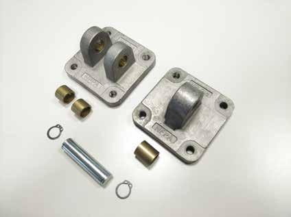
The FlangeLock™ Tool is the ultimate contamination control tool for protecting your hydraulic systems. It allows for the simple sealing of open SAE code 61, 62 & CAT-Style hydraulic flanges without tools. Constructed from lightweight aluminum. Easy on, easy off. Offers a leakproof solution to hydraulic system and environmental cleanliness. FlangeLock™ Tools stop the mess!

Have a Purchase Order? Please email to sales@flangelock.com or fax to 203-622-1238
www.hydraulex.com
Hydraulex provides the largest offering in the industry of Remanufactured, Aftermarket, and OEM hydraulic components and parts such as pumps, motors, valves, cylinders and PTOs. We also offer complete hydraulic repair services for almost every make and brand of hydraulic component. Whatever your needs, we’re sure to be able to help.
Visit our website for more information (www.hydraulex.com), give us a call (1-800-422-4279, or email us at sales@hydraulex.com.
www.acepumps.com

Ace Pump Corporation has provided pumping solutions for the chemical application, off-highway equipment, air conditioning, and refrigeration markets since 1945. These varied applications have required Ace to successfully overcome a wide range of engineering challenges.
Ace developed a complete range of products for the agricultural and off-highway equipment markets that do not require the electrical grid for operation. The pumps are found serving a variety of functions in industry today including: crop sprayers, concrete trucks, asphalt milling machines, anti-icing trucks, turf sprayers, and more.
www.laman.com
La-Man Corporation is a leading manufacturer of compressed air filtration products. With over 30 years of experience, we truly understand the importance of protecting valuable machinery, tools, and finished products from dirty, wet, contaminated air. La-Man’s line of products include the patented Extractor Dryer, .01 micron filter, as well as, LA-MAN-Air Breathing Systems™, SuperStar™ Membrane Dryers, and the Refrigerated Extractor/Dryer.
PO BOX 328 • Mazeppa, MN 55956 800-348-2463

www.mainmanufacturing.com
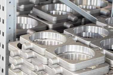
Main's website provides quick access to the 120 page catalog that includes popular styles of MAIN Manufacturing’s extensive offering of carbon and stainless Hydraulic Flanges and Components – ready for immediate shipment. Metric ordering information, weld specs, and dimensional information included. The “Quick Reference Guide” helps specify less popular items often stocked or quickly manufactured (generally 3-4 days) at our US plant. “Create-AFlange” offers more parts than the catalog — by picture. If it’s not here, or for questions, E-mails may be sent to get your answer quickly.
1-800-521-7918 info@mainmfg.com
www.oilrite.com
Oil-Rite manufactures 303 stainless steel flow sights which permit visual observation of liquid flow, clarity, and condition in lowpressure oil lines. Stainless steel is becoming a preferred material in industrial settings because of its corrosive resistant properties. They are available with or without a nylon ball for gauging the direction of fluid movement. Consult Oil-Rite’s online product catalog.
P.O. Box 1207 Manitowoc WI 54221-1207 (920)-682-6173 sales@oilrite.com
www.youngpowertech.com

Young Powertech Inc. is a manufacturer and distributor of complete lines of Mechanical and Hydraulic components. Our strength is delivery of solutions packages to fit most applications using Gear reducers, Helical Rotary Actuators, Radial, Axial, Bent Axis motors and Piston pumps and Gear pumps, Wheel and Track Drives, and complete Electric Drives Systems for mobile equipment. With decades of experience and most advance production in suppliers' factories, Young Powertech delivers more solutions than most.
Visit our website for more information.
2021 Electric Utility Fleet Managers Conference
June 8-9 & 15-16 | Virtual Event
Essential Tools For Fleet Excellence
Join fleet professionals from investor-owned electric utilities, electric cooperatives and electrical contractors from across the U.S. and Canada and the industry’s leading manufacturers and service providers for a virtual experience unlike any other.
Buy One, Get Two registrations & discounted rates
Valuable information for your fleet management team at a lower cost.
Register at EUFMC.com
L Trick of the IGHT

Unmasking Phantom Particles
By Robert Ihrig, CPM, CFPHS, Applications Engineer, Filter Systems and Diagnostics (IoT), Schroeder Industries
IMAGINE THIS: You have been filtering 30 gallons of hydraulic fluid in off-line filtration with staged 5- and 1-micron filter elements at a processing rate of 5 gallons per minute (300 gallons per hour). You have been using a light-blockage method (LBM) automatic particle counter to verify the fluid cleanliness. The starting cleanliness per ISO 4406:2017 was 25/22/15. After eight hours, the cleanliness has only dropped to 22/20/13. You’ve checked that the filter element is not clogged and not in bypass. You even went through the trouble of making sure there was an element actually in the filter. How is this possible? What you’re likely experiencing is a classic case of “phantom” particle counting.
Ç Demystifying phantom particles
Phantom particle counting is a documented problem with laser particle counters that use LBM to verify the cleanliness of petroleum-based fluids containing certain insoluble additives. Silicone-based antifoam agents are common interferents. Fluids used in mobile fluid power systems are typically formulated to contain high antifoam concentrations. Research has suggested that through differential surface tension, the silicone antifoam additive agents adhere to the inner wall of microscopic entrained air bubbles, resulting in micelle-like encapsulations of the additive agents that then take on the apparent shape characteristics of a water droplet. The micelle-like antifoam agent encapsulations typically range from 4μm to10μm in size. Once the encapsulations rise to the fluid surface, the agents quickly pierce the air bubble and return back into the fluid. In a related study of the effects of a variety of nonsolid contaminants and additives on LBM particle-counting accuracy, it was found that a base stock mixture containing 0.02% (by weight) of a silicone antifoam agent increased the particle count by a minimum factor of three. The erroneous particle accounts were particularly evident in the 4μm and 6μm channels of the ISO 4406 cleanliness standard.
Ç Limitations of LBM
LBM particle counters are useful in many applications, and the principle of the method is fundamentally simple. Fluid flows through a measurement cell containing a light source on one side of the measurement cell and a receiver (photodetector) on the opposite side. The light source becomes partially blocked as particles pass through the measurement cell, creating a light radiation differential, that is, a shadow, corresponding to the circular cross-sectional size of the passing particles.
Because of this fundamental operating principle, LBM particle counters suffer from a key drawback: the inability to discern solid contaminates from other contaminates like water, air bubbles, phantom particles, and so on. So how can the phantom particles be overcome using automatic particle-counting technology? There is an alternative solution.
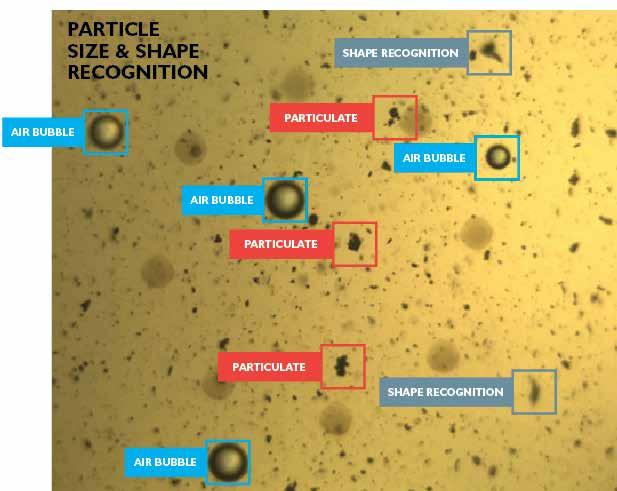
Ç Direct digital imaging method
Direct digital imaging particle counting uses size and shape-recognition technology based on advanced algorithms to distinguish contaminates. For example, a direct digital imaging particle counter can distinguish contaminates into fatigue, cutting and sliding wear, and fiber and air bubble categories based on shape characteristics. It can also recognize water droplets (though water droplets are typically not recorded). The distinction of contaminates allows for more accurate particle counting by negating nonsolid contaminates like entrained air bubbles and water droplets. Therefore, direct digital imaging particle-counting technology can negate the micelle-like antifoaming additive encapsulations as water droplets – phantom particles – allowing users to understand the condition of their fluids with greater confidence. Two case studies demonstrate how the Schroeder Pro: Total Fluid Health (TFH), a fluid-condition monitoring solution with direct digital imaging particle-counting technology, can overcome phantom particle counting.

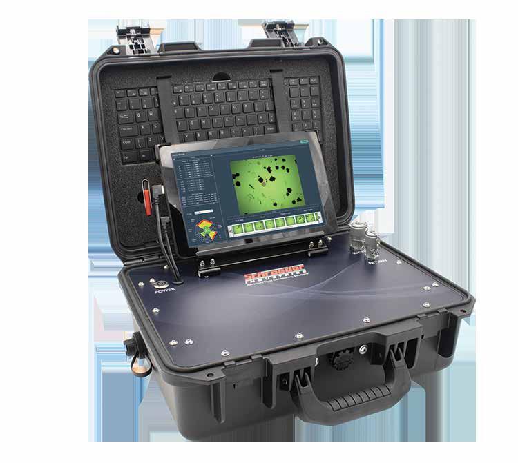
Ç Schroeder’s TFH
It’s no secret that understanding fluid cleanliness is imperative for strategically maintaining fluid-powered and lubricated machines. Automatic particle counters using LBM are generally considered reliable solutions for fluid-condition monitoring. However, LBM particle counters can yield inaccurate measurements while processing fluids that are contaminated by water, entrained air, or high levels of certain additives. Silicone-based antifoaming agents are common, well-documented additive interferents that become encapsulated within entrained air bubbles and lead to phantom particles, which are indiscernible by LBM particle counters due to their fundamental principle of operation. Research suggests that phantom particles can lead to LBM particle-counter measurements three classes higher than the true cleanliness per ISO 4406. While they can be filtered out, the additives that can lead to phantom particles serve important, specific functions and should not be removed or sacrificed. An alternative solution to LBM automatic particle counting, the direct digital imaging method uses size- and shape-recognition technology in tandem with advanced data-driven algorithms to distinguish solid contaminates from nonsolid contaminants like water droplets and air bubbles. Because of the apparent water droplet-like shape characteristics of the antifoam encapsulations, direct digital imaging solutions such as the TFH can indirectly negate the phantom particle counts and provide more accurate fluid cleanliness measurements. CASE STUDY 1
An OEM of large off-highway equipment was experiencing continuous particle-counter inaccuracies at a verification stage of assembly. The rejections due to fluid condition were mounting, causing delayed shipments and significant related costs. The average holding time delay due to rejection was seven days and incurred a holding cost of $1,500 a day per unit. At the consultation phase of the case study, eight units had been delayed.
The diagnosis was in: the existing light blockage-type particle counters were providing inconsistently high and erroneous particle counts. The ISO 4406 cleanliness would frequently measure 23/22/19, despite a strong fluid-maintenance and conditioning regime. Third-party fluid analysis reports and fluid datasheets suggested that the synthetic hydraulic fluid contained a high concentration of a siloxane (silicone derivative) antifoaming additive known to cause phantom particle measurements in LBM automatic particle counters.
Schroeder Industries provided an extensive on-site demonstration that proved the advanced direct digital imaging technology of the TFH portable fluid-contamination monitoring solution, which measured an average ISO fluid cleanliness of 15/14/10, allowed the customer to successfully process the fluid and pass six units during the first day of demonstration. The two remaining backlogged units passed early on the second day of demonstration. The realizable savings evidenced by the demonstration equated to approximately 35% in cost savings and an 81% reduction in holding time.
CASE STUDY 2
Similar to case study 1, an OEM of mobile equipment was measuring unusually high particle counts with an LBM particle counter after switching to a new hydraulic fluid type with a higher concentration of an antifoaming additive. Coincidentally, the fluid type was nearly equivalent to that used by the off-highway equipment OEM. According to the customer, the average particle count of four samples of fluid collected from the customer’s well-conditioned bulk fluid storage measured 25/23/20, as shown in table 1.
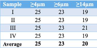
Table 1: Sample cleanliness results of fluid containing a high concentration of antifoaming additives according to ISO 4406.
After consulting the customer of the phantom particle-counting issue, Schroeder Industries offered to process fluid samples using a third-party LBM particle counter and the TFH portable fluid-contamination monitoring solution to determine if there was evidence of the phenomenon. Because of the tell-tale symptoms of particle-counting inaccuracies due to phantom particle counting, the results of the tests shown in table 2 are not surprising; the test results are consistent with typical cleanliness discrepancies produced by phantom particles.
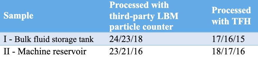
Table 2: Comparative sample cleanliness results of fluid containing a high concentration of antifoaming additives according to ISO 4406.
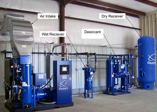
TYPES AND APPLICATIONS OF COMPRESSORS
The generic term “supply side” is often used to refer to the complete package that includes the compressor, drive motor and associated hardware, as well as the filters and coolers used to remove the contaminants and water resulting from the compression process. Also included will be items such as the receiver and capacity control devices, like a pressure switch to cycle the compressor on and off or the more complicated inlet control devices that restrict the air flow while the compressor continues to run. In addition to selecting the size and type of compressor to be used, the following items need to be considered in the flow path as the air is transported from free air at the compressor inlet to the receiver prior to being dispersed to the points of use.
Location of the compressor: The foundation that the compressor will be mounted on needs to be substantial enough to provide support and also be able to absorb any vibration produced by the compressor. The base should permit the compressor to be mounted level and not subject to any deflection in the drive. In very large systems the subsoil characteristics should be verified to insure they can withstand the dynamic loads imparted by the compressors. The compressor room should also have the means to dissipate the heat generated by the compressors. Compressor inlet location: The inlet temperature of the compressor can affect the delivery by almost 20%. Based on a normal intake temperature of 60°F, the compressor delivery will increase to 118% for an inlet temperature of -20°F and be reduced to 83.8% at an inlet air temperature of 160°F. Ideally the compressor inlet should be mounted outdoors at least 6 ft. above the ground. It should be screened and protected from direct ingestion of rain, snow, and blowing dust or debris, as well as exposure to vermin. The intake should not be mounted directly adjacent to a wall or in a confined area to minimize vibrations caused by the intake pulsations. The intake piping should be adequately sized for the airflow and have minimal bends; any bends should be comprised of large radius elbows. The inlet filter should be mounted as close to the compressor as possible. The inlet filter protects the compressor from particles larger than 20 to 80 microns that may cause wear to rings and other close fitting parts. Compressor discharge filtration: The compressor inlet filter is sized to eliminate contaminants that could damage the compressor. During compression the remaining particles have been concentrated as a function of the compression ratio. The compressor also introduces wear particles into the airstream and residual lubricating oil. Compressors that utilize oil as a cooling and sealing media will have a sump and separator to recover the compressor oil. Additional filtration will be used to further remove contaminants including particulates and residual compressor oils, after the air is cooled and the water removed.
Cooling: During compression, air molecules become compressed and generate heat, which in turn reduces the volumetric efficiency of the compressor. Losses are kept to a minimum by dissipating the heat through fins on the compressor for air-cooled compressors or into the coolant for liquid-cooled compressors. The compressed gas also cools in the receiver.
Intercooler
First stage cylinder Second stage cylinder In a typical two-stage reciprocating piston compressor, a large firststage piston feeds compressed air into a smaller second-stage piston. To improve volumetric efficiency, an intercooler cools the compressed air between stages. The intercooler often consists of a finned tube cooled by the flywheel fan. The heat of compression is transferred from the hot air to the core tube, to the fins, and then to atmosphere. Cooling is aided by the flywheel fan, which also cools the case, cylinder, and head of the compressor.
Compressor isolation: If a shutoff valve is installed in the discharge line to permit maintenance of the compressor without bleeding down the entire air system, an overpressure safety valve constructed to ASME standards must be installed upstream of the shutoff valve. A bleed-off valve should be installed to permit any residual pressure to be released prior to beginning maintenance. Proper lock-out tag-out procedures should be followed to insure the compressor is not able to start inadvertently due to the normal air demand control sequence.
Water removal: Water vapor, which is held naturally in air, is compressed with the air and will precipitate out during the compression process. If unconditioned compressed air is sent downstream it will contaminate the piping system along the way with liquid water that drops out of suspension and enters air tools and machinery. For this reason the water must be removed. An aftercooler attached to the compressor outlet will

remove most of the water before it gets into the piping system. In practice, aftercoolers placed immediately downstream of a compressor can remove approximately 85% of the moisture that passes through the compressor. For example, 1,000 cu-ft. of saturated air at 14.7 psia and 80°F contains about 1.58 lb. of water. Compressing that air to 100 psig and then cooling it back to 80°F will reduce the moisture content by about 90% to about 0.2 lb.
The receiver conditions air the same way. As air cools in the receiver, water condenses, and falls to the bottom of the receiver, where it is drained off. Other methods used to further reduce the water content in compressed air include refrigeration or desiccants such as activated alumina. Sumps that collect the condensate must be designed so the drained fluid can be captured for proper disposal.
Compressor Types
Air compressors commonly used for power and control functions are reciprocating piston, vane, rotary screw, rotary lobe, scroll, and centrifugal types. A vacuum pump is treated as a compressor that works at less than atmospheric conditions. Within each of these types of compressors, additional distinction can be drawn for single-stage, dual- or multiple-stage, and oil-injected or oil-less. In single-stage compressors the air passes through a single compression stage. The effective maximum compression ratio is 11:1, limiting effective outlet pressures to 1,030 kPa (150 psig.) In dual- or multistage compressors the air is passed into an additional compressor and further elevates the pressure. The air passes through an intercooler to reject some of the heat of compression to improve compressor efficiency. When discharge pressures of 1,750-2,400 kPa (250-350 psig) are required, two- or threestage compressors are preferred. For extremely high pressures above 4 MPa (600 psig), four- or five-stage compressors will be used.
Dryer
Compressor mounted on receiver.
Rotary screw compressor.
Vane compressor.
Reciprocating piston: The reciprocating piston compressor is similar in design to an internal combustion engine with a piston connected to the crankshaft by some form of connecting rod. The compressor can have multiple pistons and may be either single acting or double acting, resulting in compression strokes in both directions of the piston. Multistage compressors will connect the discharge from one cylinder though an intercooler to another cylinder of a smaller size to increase the compression ratio. Lubrication of the crank mechanism and pistons varies based on the design. For applications where trace amounts of oil are tolerated, the lubrication is similar to conventional internal combustion engines, using positive lubrication or the splash type commonly found on small engines. For oil-less or oil-free compressors the bearings will be prelubricated and sealed, the piston seals will be made of a low-friction material that is self-lubricating and heat resistant. Valves identified as reed, disc, or strip are check valves that open with a very low differential pressure. Larger compressors may use an automotive-style valve system driven off the crankshaft. Air cooling is the most common method, with liquid cooling limited to large compressors or those with high duty cycles.
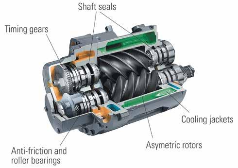
Rotary screw: According to the Compressed Air and Gas Institute, the oil-injected rotary screw compressor has become the dominant type of compressor for a wide variety of industrial and mining applications. The rotary screw compressor is a positive displacement device that utilizes two intermeshing helical rotors in a stator housing. The main rotor consists of a series of helical lobes that mesh precisely with the corresponding grooves in the secondary rotor. As the rotors turn, air that enters the inlet is transported progressively along the rotors away from the inlet to the discharge port. Oil is injected into the compression chamber to provide sealing, lubrication, and cooling. The oil used is typically a synthetic lubricant to provide long life at high compressor operating temperatures. The air-oil mixture leaving the compressor is then passed into a sump/separator to recover the oil, which is then filtered, cooled, and reinjected into the compression chamber. Oil-free rotary screw compressors utilize external gears to prevent the intermeshing rotors from making physical contact. The lack of oil for the sealing and cooling requires higher rotor speeds, and single-stage versions produce less air volume since none of the heat of compression is removed from the air during the process.
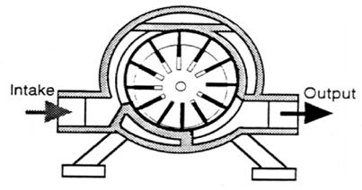
Vane: Sliding vane devices can be designed to operate as an air compressor or vacuum pump. Sliding vane compressors consist of a cylindrical stator with a smaller diameter rotor mounted eccentrically inside. The stator chamber is the same width as the rotor. The diameter difference of the rotor (Continued on page 18)
(Continued from page 17) and stator and the thickness of the chamber will determine the amount of air produced with each revolution of the rotor. The rotor has a number of slots fitted with vanes that are free to slide in and out. Driving the rotor causes the vanes to extend due to centrifugal force. The vanes form a seal against the inside diameter of the stator, the rotor, and the ends of the cylindrical stator. The inlet port allows air to be drawn in on the increasing volume side of the eccentric, where the vanes slide out of the rotor. As the chamber formed by two vanes, the rotor and the inside edge of the stator reaches the major diameter, the inlet port is blocked and the discharge port is then opened as the chamber now passes to the decreasing volume area caused by the eccentric. The vanes are forced back into the rotor and the air is forced into the discharge port by the reduced volume. Oil is typically injected into the airstream to provide lubrication, cooling, and sealing of the moving parts.
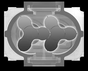
Lobe: The twin lobe compressor uses gears to synchronize two intermeshing lobe-shaped rotors. The air is transported around the outside of the housing from the inlet to the outlet. The meshing of the rotor lobes forces the air out on the discharge side while the separating of the
Lobe compressor.
Scroll compressor.
Centrifugal compressor. lobes on the inlet side draws air into the pumping chamber. These compressors are typically used for large volumes of low-pressure air, or in transporting process gasses for scrubbers and similar applications.
Scroll: The scroll compressor utilizes an oscillating spiral that fits inside a mating fixed spiral or scroll. The orbiting movement of the oscillating spiral creates a flow path that progressively moves from the inlet to the outlet. The precise shape and fit of the two scrolls provides a tight seal without actual metal-to-metal contact and does not require lubrication. The result is a continuous discharge of oil-free air with no pulsations and very low noise. Currently they are limited to 3.75 kW (5 hp).
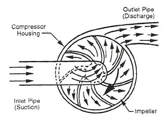
Centrifugal: A centrifugal compressor is usually used in large horsepower applications, typically above 300 hp. It is a nonpositive displacement compressor technically defined as a dynamic compressor. The air is accelerated and compressed as a result of impacting the rotating vanes or impellers. Stationary guide vanes are used to direct the airflow within the compressor. Multistage compressors may be in-line on a single shaft with intercoolers located between the stages, or integrally geared consisting of a set of separate impellers and housings connected by a common drive gear. Performance of the centrifugal compressor is significantly affected by the discharge pressure and the rotational speed of the compressor.
TEST YOUR SKILLS
1Which of the following is the preferred location for the compressor inlet? a. Inside the compressor room. b. Inside the building close to the main demand location. c. Outdoors at least 6ft. (2m) off the ground. d. Outdoors close to a wall and an adjacent corner. e. Indoors under a stairwell.
2Which compressor type is defined as a dynamic compressor? a. Centrifugal. b. Reciprocating piston. c. Rotary screw. d. Vane. e. Lobe.
See page 31 for the solutions.


