

NOVEMBER 2022 fluidpowerjournal.com Avoiding Hydraulic Hose Disasters Circular Sustainability for Fluid Power All About Vacuum NFPA Shipments Report KEEPING PACE WITH MATERIAL HANDLING Nonprofit Organization USPostage PAID Bolingbrook,IL Permit#323 Innovative Designs & Publishing • 3245 Freemansburg Avenue • Palmer, PA 18045-7118
CONNECT WITH TOP MANUFACTURES
International Fluid Power Exposition
the place where engineers meet to:
new ideas
solutions
unique
new partners
suppliers

other
KEN ROSENBECKER SALES MANAGER NORTH AMERICA

happens
20% OFF REGISTRATION

WIPRO INFRASTRUCTURE ENGINEERING

INTERNATIONAL FLUID POWER EXPO MARCH 14-18, 2023 LAS VEGAS, NV, USA The
(IFPE) is
“ There’s no
show in the world I think that brings the OEM machine manufacturers and the suppliers as close together as this show. It’s a good place to meet and learn about what’s going on. In the Americas, in the Western Hemisphere, this is the show for fluid power.”
|
IFPE only
once every three years! SAVE
Register now at IFPE.com and type AD20 in the Promo Code box Discover
current
can offer to your
challenges. Find
among suppliers pushing the envelope on what fluid power can do.
CO-LOCATED WITH CONEXPO-CON/AGG (two shows, one price) Including Bosch Rexroth , Danfoss Power Solutions , Poclain , IFM Efector , Hawe Hydraulik , Husco , and 375+ more! Join your peers from these OEMs: ∙ Caterpillar Inc ∙ Volvo Construction Equipment ∙ Liebherr ∙ CASE Construction Equipment ∙ Komatsu ∙ John Deere Construction ∙ Doosan Bobcat ∙ KOBELCO Construction Machinery USA ∙ LBX Company Spark
with in-depth technical conversations with other engineers. The #1 Trade Show & Conference for Fluid Power, Power Transmission, and Motion Control IFPE20_210x285+3x4.5mm_Bleed_Registration_Ad_062722.indd 1 6/27/22 7:09 PM



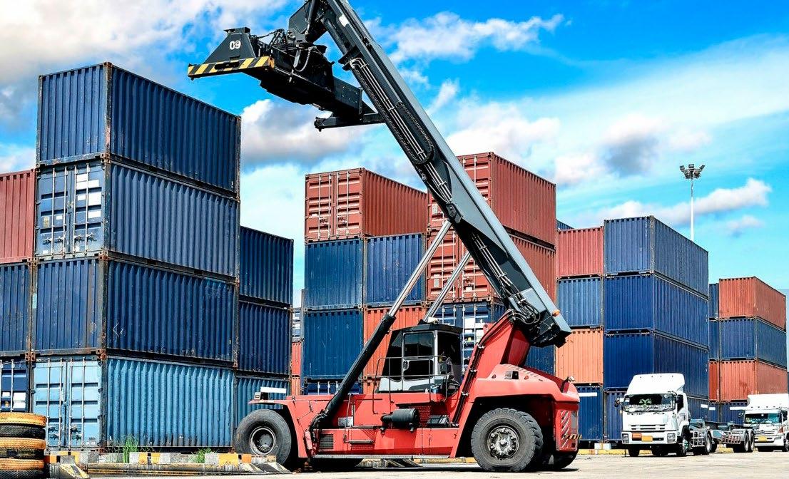

Features 6 Cover Story Carry On: Fluid Power Keeps Pace with Material Handling Fluid power systems in advanced material handling applications with complex motion control. 10 Test Your Skills Sizing and Selecting Vacuum Pads 18 All Around the World: Circular Sustainability for Fluid Power Seeing manufacturing not as a linear process that ends in a landfill, but as a continuous cycle. 24 Checked: Avoiding Hydraulic Hose Disasters Some best practices to care for a crucial component to most systems. 28 Without Skilled Tradespeople, Who Builds It? Can fluid power lure young people to careers offering financial stability and job satisfaction? IN THIS ISSUE Publisher’s Note: The information provided in this publication is for informational purposes only. While all efforts have been taken to ensure the technical accuracy of the material enclosed, Fluid Power Journal is not responsible for the availability, accuracy, currency, or reliability of any information, statement, opinion, or advice contained in a third party’s material. Fluid Power Journal will not be liable for any loss or damage caused by reliance on information obtained in this publication. NOVEMBER 2022 VOLUME 29 • ISSUE 11 20 6 Departments 4 Notable Words 5 Figure It Out 12 NFPA Update 13 IFPS Update 20 Product Spotlight 22 Web Marketplace 23 Component Showcase 26 All About Vacuum 31 Classifieds Cer tification Empowers Opportunity. 18
ZF SERIES HYDRAULIC FLUIDS ECO



BIO-BASED GREEN SERIES
MARINE SAFE SERIES
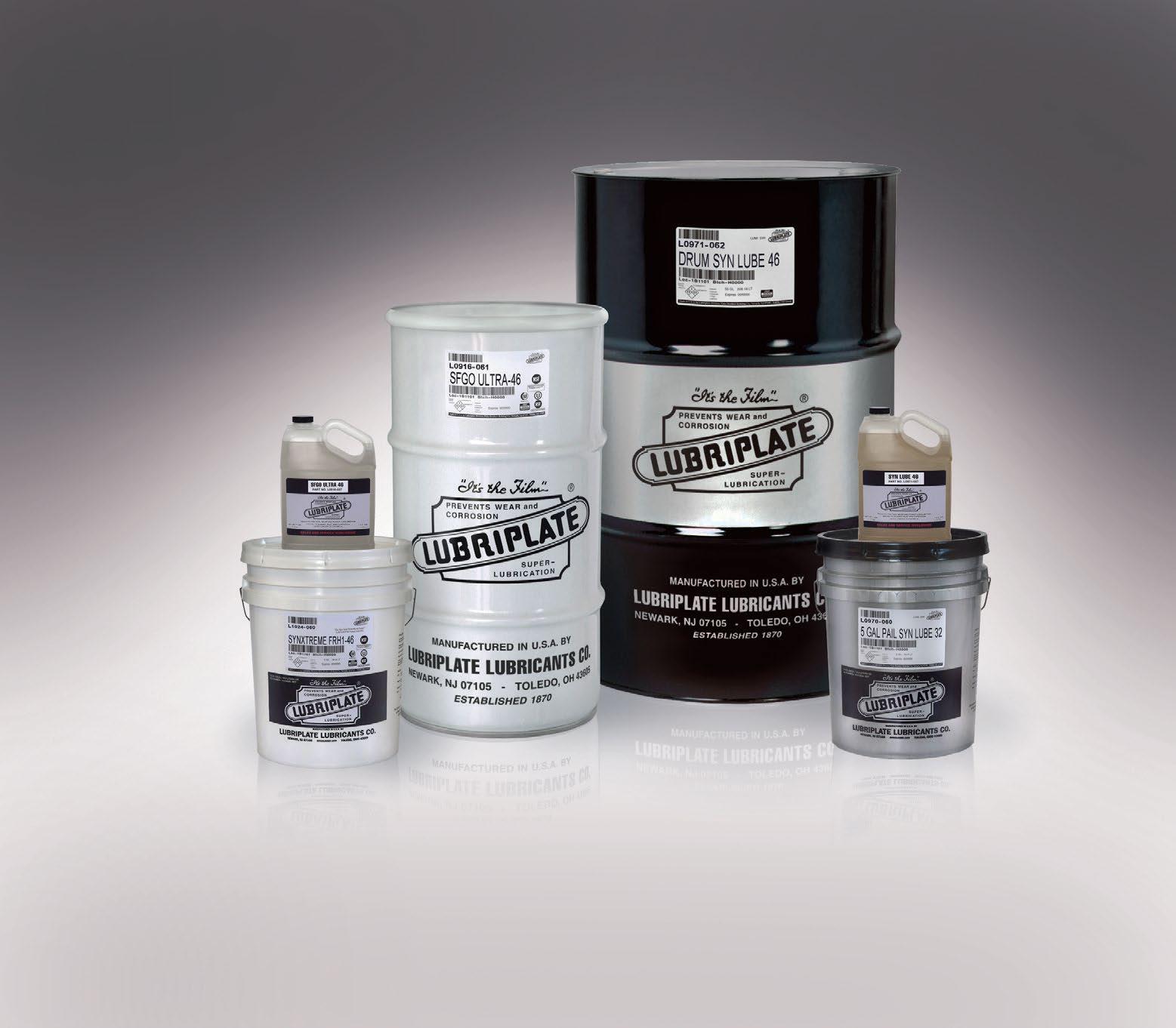

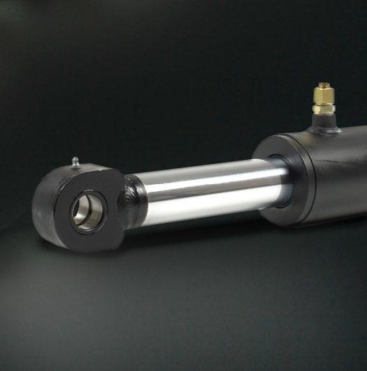
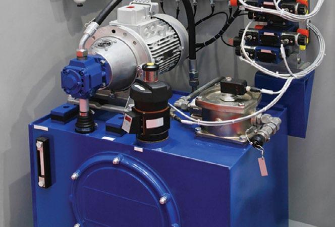
Newark, NJ 07105 / Toledo, OH 43605 / 800-733-4755 To learn more visit us at: www.lubriplate.com INCLUDED AT NO ADDITIONAL CHARGE ES P Lubriplate’s Complimentary Extra Services Package COLOR CODED LUBE CHARTS & MACHINERY TAGS PLANT SURVEYS / TECH SUPPORT / TRAINING LUBRICATION SOFTWARE / FOLLOW-UP OIL ANALYSIS LUBRICANTS HYDRAULIC FLUIDS WITH THE POWER TO PROTECT VGP COMPLIANCE STATEMENT - LUBRIPLATE BIO-SYNXTREME HF Series Hydraulic Fluids are Environmentally Acceptable Lubricants (EALs) according to the definitions and requirements of the US EPA 2013 Vessel General Permit, as described in VGP Section 2.2.9 SYN LUBE SERIES 32-68 100% • High-Performance, 100% Synthetic, Polyalphaolefin (PAO)-Based Fluids. • Provides extended drain intervals and excellent compatibility with seals. • Available in ISO Viscosity Grades 32, 46 and 68. HO SERIES HYDRAULIC OILS PETROLEUM • Premium-Quality, Petroleum-Based Hydraulic Oils (ISO Grades 32-100). • Anti-wear fortified to protect hydraulic system components. • High aniline points ensure long seal life with fewer leaks. SFGO ULTRA SERIES 7-68 NSF H1 • NSF H1 Registered and NSF ISO 21469 Certified - Food Machinery Grade. • High Performance, 100% Synthetic Food Machinery Grade Fluids. • Available in ISO Viscosity Grades 7, 15, 22, 32, 46 and 68. • Fortified with Lubriplate’s proprietary anti-wear additive SYNXTREME FRH1-46 • High-Performance, FM Approved, Fire Resistant Hydraulic Fluid. • NSF H1 Registered and NSF ISO 21469 Certified - Food Machinery Grade. • ECO-Friendly, Readily Biodegradable (OECD 301F). • Fortified with Lubriplate’s proprietary anti-wear additive .
• Heavy-Duty, High-Performance, Extended Life, Hydraulic Fluids. • ECO-Friendly - Free of zinc or silicone compounds. • Provides long service life and extended fluid change intervals.
ECO • Vegetable-Based Oils for use in environmentally sensitive applications. • ECO-Friendly - Ultimately Biodegradable (Pw1). • Zinc-free additives provide exceptional anti-wear and anti-rust protection.
ECO • For equipment operating in environmentally sensitive locations. • Zinc-free and non-toxic to aquatic life. • Exceeds U.S. EPA LC50 and US Fish and Wildlife requirements. • Meets or exceeds the requirements of most hydraulic equipment BIO-SYNXTREME HF SERIES ECO • Advanced Synthetic Polyalkylene Glycol (PAG)-based hydraulic fluids. • Designed for environmentally sensitive industrial and marine applications. • Meets U.S. EPA Vessel General Permit (VGP) Requirements. Readily biodegradable. • Does not leave a sheen on the water. FM APPROVED FIRE RESISTANT NSF H1 REGISTERED FOOD GRADE SYNTHETIC PAO-BASED OILBASED REGISTERED FOOD GRADE ZINC-FREE FRIENDLY BIO-BASED FRIENDLY, NON-TOXIC TO AQUATIC LIFE (LC-50) FRIENDLY - MEETS VGP REQUIREMENTS Lubriplate’s complete line of ultra high-performance, hydraulic fluids has been designed to provide a wide range of benefits including: extended fluid change intervals, cooler operating temperatures, reduced friction and reduced downtime. Products include...
Fluid Power Rides a Wave of Change
By Kevin P. Vanderslice, Director of Mobile Sales, ifm efector

» THE LAST 18 MONTHS have been a challenge for everyone, as we deal with supply chain issues, the lingering effects of the COVID shutdown, and the inflationary prices of core commodities. In an ideal world, there are checks and balances to prepare, but these are unprecedented times we are dealing with. The world in fluid power started changing before 2020. Each of us is on a journey to digital transformation, and each of us is in a different phase in that journey.
In most of these conversations we do not discuss the why: Why is data important? Why are we using smart sensors?
As an example, let us look at telematics. Today we address a lot of the how and what commodities. Metrics, such as vehicle tracking, are used by 85% of fleet owners. This tells you where the vehicle is always located. However, it does not tell you how efficient the driver may be at planning the route. The car broadcasts data such as machine speed, fuel consumption, and temperature from the engine. It may also record additional inputs such as hydraulic oil, level, pressure, and humidity. This broadcast data is useful, but it does not tell you about impending maintenance issues. Finally, if we look at driver-performance monitoring, it is normally represented in data tracking accelerating or braking styles and how efficiently the driver followed the planned route. It does not explore the possibility of the driver looking down at his or her cell phone.
There is a shift in business models with this digital transformation, and each of us are in a different stage. For the past number of decades, most of us have navigated the waters of Wave 1. This is the classic ownership model, in which you pay a one-time price for a machine or after-sales service. An OEM provides a warranty for a limited time, and any service work beyond that follows the classic model of sending a technician or bringing the machine in for repairs. Wave 2 is the usage-based model, in which a customer pays for the actual usage of the machine but does not own it. In Wave 2, uptime becomes critical. If your machine is not performing at 100%, you may not get paid. Now you need more insights into the machine operation to detect wear and tear. With this information, you can schedule downtime for maintenance and repairs.
The term “digital transformation” is certainly buzzy these days. But how should fluid power companies manage this transformation? The manufacturing industry generates more data than any other sector of the economy, and because all this data is generated, companies are making data and analytics a priority. In a recent General Electric survey, 42% of manufacturers have said “big data” is a top priority. In the same survey, another 45% said that it is one of their three highest priorities. Today we talk a lot about the what and the how. What are big data, IIoT, and Industry 4.0? How are smart sensors, software, machine learning, and artificial intelligence connected?
Lastly is the final stage, Wave 3, the outcome-based model. The cus tomer only pays for the finished product and does not care which machine achieves it. However, you are responsible for the final product, and having a full understanding of the machine health and product quality is critical. The classic consumer example of Wave 3 is Uber.
As we mitigate these in the times in which we live, the digital trans formation movement is ongoing. We need to determine which wave we are in and which one our clients expect from us in the future. This could take a few months or many years. The main point is – we need to prepare ourselves for this change. •
4 NOVEMBER 2022 WWW.FLUIDPOWERJOURNAL.COM • WWW.IFPS.ORG NOTABLE WORDS
PUBLISHER
Innovative Designs & Publishing, Inc.
3245 Freemansburg Avenue, Palmer, PA 18045-7118
Tel: 800-730-5904 or 610-923-0380
Fax: 610-923-0390 • Email: Art@FluidPowerJournal.com www.FluidPowerJournal.com
Founders: Paul and Lisa Prass
Associate Publisher: Bob McKinney
Editor: Michael Degan
Technical Editor: Dan Helgerson, CFPAI/AJPP, CFPS, CFPECS, CFPSD, CFPMT, CFPCC
Director of Creative Services: Erica Montes
Graphic Designer: Nicholas Reeder
Account Executive: Kristy O'Brien
Accounting: Donna Bachman, Sarah Varano
Circulation Manager: Andrea Karges
INTERNATIONAL FLUID POWER SOCIETY
1930 East Marlton Pike, Suite A-2, Cherry Hill, NJ 08003-2141
Tel: 856-489-8983 • Fax: 856-424-9248 Email: AskUs@ifps.org • Web: www.ifps.org
2020 BOARD OF DIRECTORS
President: Denis Poirier Jr., CFPAI/AJPP, CFPHS, CFPIHM, CFPCCDanfoss Power Solutions
Immediate Past President: Rocky Phoenix, CFPMMHOpen Loop Energy
First Vice President: Scott Sardina, PE, CFPAI, CFPHS, CFPECS - Waterclock Engineering
Treasurer: Jeff Hodges, CFPAI/AJPP, CFPMHM - Altec Industries
Vice President Certification: James O’Halek, CFPAI/AJPP, CFPMIP, CMPMM - The Boeing Company
Vice President Marketing: Chauntelle Baughman, CFPHSOneHydraulics
Vice President Education: Randy Bobbitt, CFPAI, CFPHSDanfoss Power Solutions
Vice President Membership: Garrett Hoisington, CFPAI/AJPP, CFPS, CFPMHM - Open Loop Energy
DIRECTORS-AT-LARGE
Stephen Blazer, CFPE, CFPS, CFPMHM, CFPIHT, CFPMHT - Altec Industries
Steve Bogush, CFPAI/AJPP, CFPHS, CFPIHM - Poclain Hydraulics
Cary Boozer, PE, CFPE - Motion Industries
Lisa DeBenedetto, CFPS - GS Global Resources
Daniel Fernandes, CFPECS, CFPS - Sun Hydraulics
Brian Kenoyer, CFPHS - CemenTech
Jon Rhodes, CFPAI, CFPS, CFPECS - CFC Industrial Training
Mohaned Shahin, CFPS Parker Hannifin
Randy Smith, CFPHS - Northrop Grumman
Ethan Stuart, CFPS, CFPECS - Wainbee Limited
Brian Wheeler, CFPAI/AJPP, CFPMM, CFPMIPThe Boeing Company
HONORARY DIRECTORS-AT-LARGE AND EX OFFICIO
Donna Pollander, ACA Paul Prass, Fluid Power Journal
Liz Rehfus, CFPE, CFPS
Robert Sheaf, CFPAI/AJPP - CFC Industrial Training
IFPS STAFF
Chief Executive Officer: Donna Pollander, ACA
Technical Director: Thomas Blansett, CFPS, CFPAI Certification Logistics Manager: Kyle Pollander Communications Coordinator: Victoria Piro
Layout/Graphics Designer: Chalie Clair
Assistant Director: Jenna Mort Bookkeeper: Diane McMahon Administrative Assistant: Beth Borodziuk
Fluid Power Journal (ISSN# 1073-7898) is the official publication of the International Fluid Power Society published monthly with four supplemental issues, including a Systems
New Problem Relocating HPU Causes Start-up Problem
By Robert Sheaf, CFPAI/AJPP, CFPE, CFPS, CFPECS, CFPMT, CFPMIP, CFPMMH, CFPMIH, CFPMM, CFC Industrial Training
» A CUSTOMER WAS rearranging his shop floor to accommodate a new assembly line. They moved a clamp and grind machine to a location where there was too little room to place the HPU close to the machine. The existing hoses connecting the two were 30 feet long and routed through a hole in a wall to the unit.
The company realized that the longer hoses needed their size increased to account for the pressure drop caused by their new length.
But they encountered a problem during start-up. The cylinder wasn’t responding as in the past. It could not reach max speed extending, and there seemed to be little con trol of the retract speed. The counterbalance valve was mounted close to the cylinder.
They installed a new counterbalance valve, but there was no change. Even a new proportional valve didn’t help.
What could be the problem?
Solution to the October 2022 problem: Compactor Loses Pressure to All Circuits
After checking most of the normal causes for lack of pressure, I thought that the pilot orifice in the main pilot operated directional valve was plugged. When I removed the main stage of the directional valve, I found it had a check valve insert in the pressure port. This creates enough pilot pressure to shift the main spool and requires about 75 psi minimum. A piece of plastic was holding the check valve fully open. Removing the obstacle solved the lack of main system pressure. Further inspection then found that the bypass check in the pressure filter had failed and generated the plastic piece. We installed a new filter housing.
WWW.IFPS.ORG • WWW.FLUIDPOWERJOURNAL.COM NOVEMBER 2022 5
Integrator Directory, Off-Highway Suppliers Directory, Tech Directory, and Manufacturers Directory, by Innovative Designs & Publishing, Inc., 3245 Freemansburg Avenue, Palmer, PA 18045-7118. All Rights Reserved. Reproduction in whole or in part of any material in this publication is acceptable with credit. Publishers assume no liability for any information published. We reserve the right to accept or reject all advertising material and will not guarantee the return or safety of unsolicited art, photographs, or manuscripts. FIGURE IT OUT
15 H2O 3 MICRON 50 PSI BY-PASS CHECK 65 PSI CHECK SET @ 3500 PSI 5" B x 3.5" ROD x 36" LONG
CARRY ON Fluid Power Keeps Pacewith Material Handling
By Wendy Wu, Product Manager Hydraulic Hose & Couplings, Industrial Europe, Gates
Material handling takes place at every stage of the supply chain. It involves the movement, storage, protection, and control of raw materials and finished goods. Fluid power is a close partner with material handling. Fluid power systems are often used for advanced handling applications involving complex sequences of motion control. That control allows for mechanical tasks such as rotations, lifts, turns, and conveyer operations, or extremely difficult tasks, like tunnel excavation.
Optimizing material handling and improving supply chain efficiency have been constant challenges, but their scope is shifting considerably. Acceleration of e-commerce adoption on a larger scale, increased cus tomer expectations, the urgency of a green transition, and unexpected disruption of the supply chain ecosystem put additional pressure on both suppliers and buyers. Innovation is more critical than ever in supply chain management – and by extension, materials handling – for building resilience, tackling long-term challenges, and contributing to global CO2 emissions reduction targets.
Historically, material handling was not an industry that came to mind when people thought of the disruption or adoption of technologies. Now it’s a very dynamic field.
What are the focus areas and priorities for keeping up with the changing technology of the material handling industry and contributing to its future development? The answer is key for fluid power companies mapping their own innovation journey, as well as for equipment manufacturers choosing the right supplier. This article discusses major success factors of companies taking on challenges, grabbing opportunities, and thriving in this new era of material handling.
Material handling automation

The speed of the material handling industry’s embrace of automa tion and emerging technologies in recent years has been astonishing, although it varies among subsegments. Automation technology is advancing fast and creating disruptive change in material handling for product manufacturers, retail businesses, e-commerce players, and end customers. With automated conveyors, guided vehicles, and storage and retrieval systems, along with tools like warehouse cranes, goods movement can be almost entirely automated. Furthermore, artificial intelligence and the Internet of Things have paved the way for a new era of robotic material handling.
Industrial automation is not a new concept, and fluid power has several features that help automate manufacturing operations. Fluid power equipment can maintain constant and steady pressure, avoiding the overheating or failure of electric motors when exerting continuous force. This steady pressure permits the smooth motion of mechanical arms for functions such as lifting and holding heavy objects or gripping an object with a controllable force. Besides meeting technical requirements, fluid power is the preferred solution in many automation applications, especially when it is more economical than electrical power.
Digital transformation means more than adding automation. Mate rial handling is linked with advanced technologies such as self-driving, blockchain, and AI. Digital technologies are reinventing equipment, elevating it to the next level of user experience, safety, and efficiency.
The industry-first Gates GC20 crimper, for example, is supported by the Gates Cortex Intelligence automation platform. It offers real-time
6 NOVEMBER 2022 WWW.FLUIDPOWERJOURNAL.COM • WWW.IFPS.ORG COVER STORY
cloud connectivity and system integration, allowing operators of any skill level to intuitively crimp assemblies safely and error-free.

Regardless of debates about the negative effects of digitalization, we are in a digitized economy and business environment. Dig ital transformation is of strategic importance to leading fluid power manufacturers and players diving into new segments.
A ‘culture of innovation’
The remarkable shift toward increased automation and digitiza tion of material handling requires an accelerated adoption of tech nologies and adaptation to the trend. Introducing, implementing, and absorbing rapid changes in technologies can be challenging and complex. During the innovation journey, companies can fall behind simply because they do not fully understand the trend, they are reluctant to move, or they lack a system to support creativity.
The driving force is a culture of innovation. It encourages creative solutions for meeting customer needs and secures the continuous inno vation of products, processes, and services.
For example, Gates Corporation has historically been first-to-market with innovations, including the M3K constant-pressure hydraulic hose and Quick-Lok threadless snap-in hydraulic couplings. This type of inno vation culture leads people to challenge the limits, proved by the recent X-Series hydraulic innovations from Gates, featuring the MXT and MXG lines. In a disruptive age, every company needs to be a truly innovative solution provider. This is essential not only for business growth but also for surviving the transformation.
Material handling capability is a focal point for operations efficiency, supply chain optimization, and manufacturing productivity. Highly auto mated material handling systems significantly improve process efficiency. Major benefits also lie in their scalability and accuracy. They can be pro grammed to handle multiple tasks simultaneously, mitigating human mistakes and errors. However, system reliability is crucial to fully realize those benefits. Automated systems, in turn, have the ability to collect accurate data of operations and working conditions. This benefits new process and model implementation to improve system reliability, such as proactive maintenance service, which largely depends on condition-based issue prediction and data-driven activity.
Efficiency and reliability are inseparable because one requires the other for companies to increase profit and improve productivity. For components suppliers or producers of fluid power equipment, both effi ciency and reliability need to be considered when it comes to equipment development and optimization. Innovation must be compatible with reliability, helping to eliminate or greatly reduce any risk for customers who are early users of innovative practices.
Fluid power applications can impact efficiency and reliability in several ways. To illustrate, consider how the Gates MXG 5K hose contributes to system competency and dependability. It is 25% more flexible than
legacy hydraulic hoses. A more flexible hose makes it easier to get a flush mount at the manifold during installation, which reduces the risk of hydraulic fluid leaks. In dynamic applications, more flexibility means less power goes into moving the hose, so more power can be used for actual work. Tested to 1 million impulse cycles, the MXG 5K comes with an XtraTuff Plus cover that is both abrasion- and ozone-resistant, delivering long-lasting performance and reliability on the inside and the outside.
Most original equipment manufacturers find a simple solution to reduce downtime, mitigate risks, and tackle future uncertainty to increase the strength and longevity of the system. Premium-quality materials often equate to long-term durability and life. Selecting premium products is an effective way to attain product reliability and eliminate downtime in the field. High quality doesn’t mean high cost. Companies need to carefully evaluate the total cost of ownership, factoring in the original purchase price of the component, the installation time and effort, plus any maintenance costs during the operational life.
Long-term value
Mechanical reliability relies heavily on materials science and engi neering, plus operating conditions and environment. When fluid power components – fittings, hose, and tubing for hydraulic or pneumatic systems – all come from the same manufacturer, it hedges against the risk of shutdown caused by incompatible components. The Gates MXT wire braid hose and Gates MegaCrimp couplings are qualified to work together as matched systems. When assembled per Gates specifications, they are warrantied to exceed 600,000 impulse cycles, which is more than three times the industry standard. A Gates customer in Malaysia faced a leaking problem in its logistics operations every two months due to mix-and-match hose and couplings. The company resolved the issue by selecting and using the Gates MXT series and validated couplings. The Gates engineering process pays strict attention to minimizing the number of components, which reduces the number of leak paths and offers optimal longevity, efficiency, and reliability.
While efficiency and reliability improvements are primary focuses for business growth, to increase long-term business value sustainability is unignorable. It is of special concern today. In the context of business uncertainty, it raises new challenges. Every market has experienced a
WWW.IFPS.ORG • WWW.FLUIDPOWERJOURNAL.COM NOVEMBER 2022 7 Continued to Page 8
Gates’ GC20 crimper offers real-time cloud connectivity.
Continued from page 7
surge in energy prices due to rebounding demand after the COVID-19 pandemic. Global supply chains are expected to struggle amid constant volatility, and it is hard to predict when the backlog will end. Invest ment for establishing green supply chain or material handling systems undoubtedly creates value in the long term.
Material handling systems consume substantial amounts of energy over time. Electric consumption due to direct movements of products or materials by material handling is a macro-category in logistics chains. Obtaining and transporting energy is increasingly expensive. Energy savings are a strategic factor for many businesses, so the features of automated and robotic equipment they desire include energy efficiency and compact size.
Sustainability dynamics
Smart material handling enables automated procedures that employ less energy, provide real-time operational visibility, and turn data into actionable insights. There is no denying that using renewable energy in industry and power generation is a trend, but this transition will likely take some time. So the quickest way to tackle an energy crisis is with energy savings, where the adoption of lighter components of equipment can play a big role. Forklifts are one of the most widely used pieces of equipment for moving and managing materials in a warehouse and are typically outfitted with over 10 meters (32 feet) of hoses. Large scissor lifts can have hundreds of meters of hydraulic lines on one application. Weight reduction brings considerable energy-saving potential and is important for building energy-efficient hydraulic systems.

Fluid power is the preferred solution in many automation applications, especially when it is more economical than electrical power.
Every industry’s sustainable development relies on ecological sus tainability. Fluid power is no different. There is still a lot to be done to accelerate the transition toward sustainability dynamics. Steps in that direction include the formation of standards and principles in the design of green fluid power systems and advocating for environmentally safe fluids. Players with far-reaching vision have invested more in products that lessen environmental impacts, mainly by reducing noise emissions, heat generation, and oil leaks and spills from fluid power applications.
A human-robot interaction environment requires new health and safety measures.
In terms of energy conversion, pneumatics and hydraulics are effi cient solutions for a number of applications. Converting the energy of compressed air into motion, pneumatic actuators are highly efficient sources of motion control. Pneumatic control systems are economical and can be advantageously applied to other forms of power. In hydrau lics systems, pressurized fluids are transmitted over long distances and through complex machine configurations with little loss in power. An important contributor to sustainability improvement is an increased system life, reducing the impact of production and decommissioning.
The leading trend in fluid power machinery is continuous improve ment in product flexibility, compactness, and weight. Hydraulic hoses are a shining example; high flexibility helps achieve high efficiency, allowing for shorter assembly time and easier routing during installation. As examples, Gates MXT hoses (with braided high-tensile steel wire reinforcement) and the recently launched Gates MXG series hoses (with patented Xpiral woven spiral technology) are remarkably more light weight – for improved fuel economy and longer time in the field before refilling – extremely more flexible, and much more compact compared to their premium legacy equivalents.
Gates was an early adopter of environmentally friendly materials in products. In 2003, Gates launched the EFG hose series. “EF” stands for EnviroFluid, indicating the product is compatible with even the most aggressive biodegradable hydraulic fluids, such as synthetic esters, poly glycols, and vegetable oils. Key players in fluid power go beyond product designs to implement energy-saving manufacturing practices that reduce their ecological footprint. Gates facilities in Belgium and Thailand employ solar energy to lower carbon footprints. The Belgium facility is 100% solar powered and generates up to 739 kilowatts peak. The Thailand facility achieved an energy savings of 24,336 kilowatt hours per year.
Last but not least, don’t forget about people. As companies progress to an era of highly automated manufacturing and distribution, the journey can be sustainable only when we prioritize people every step along the way. The design of fluid power systems, whether in manual or automated form, must consider improved ergonomics and mitigate new health and safety risks for people who interact with robots in so-called cobotic envi ronments. Highlighting attention paid to ergonomics during the design process, Gates fluid power products are lighter weight and more flexible for ease of installation and to help reduce stress and strain when handling.
Fluid power, material handling, and supply chain share key benchmarks: efficiency, reliability, and sustainability. Driven by components manufac turers, equipment and machinery OEMs, and industry organizations, fluid power innovation is essential for companies to cope with supply chain issues and win in the new reality. Advancements in material handling offer opportunities for fluid power to make a positive impact. Along with emerging technologies reshaping virtually every industry, material han dling has fast become the objective for a steady, nonstop flow of goods, which prompts fluid power to accelerate along its road to innovation.
Innovation is a journey, not a guarantee for success. A truly innovative culture leads to sound strategy and a well-developed actions frame work. Companies must identify their focus areas, coordinate efforts, and leverage sources to hurdle current obstacles and be ready to respond to future challenges.
8 NOVEMBER 2022 WWW.FLUIDPOWERJOURNAL.COM • WWW.IFPS.ORG
•


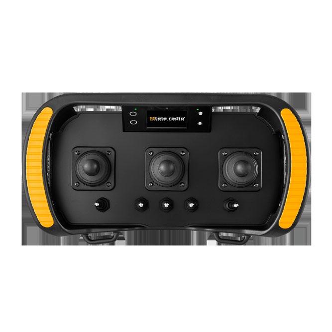




















NOVEMBER 2022 9 +1 305 459 0763 www.teleradio.com sales@teleradio.com AN COMPANY Tele Radio America, LLC REMOTE CONTROL FOR HYDRAULIC APPLICATIONS SAFE SMART STRONG SCAN FOR INFO
SIZING AND SELECTING VACUUM PADS
Vacuum pads are primarily used for handling smooth-surfaced mate rial but can be used with textured or irregularly shaped material as well. Because sheet glass and other products that have a smooth surface generally have few to no places for attaching mechanical hooks and grippers, vacuum pad technology enables the material to be efficiently and safely moved.
Because of the many applications for using vacuum pad lifting tech nology, and the many possibilities of surfaces and working environments encountered, vacuum pads come in various shapes, sizes, and materials to allow a wide selection range.
The principle behind vacuum pad technology is simple. The area of the pad multiplied by the pressure applied results in a holding force. The pressure within the pad is less than atmospheric (vacuum). The differential pressure between atmospheric and the vacuum level within the pad is the effective pressure against the area of the pad contacting the surface of the material. This results in a force holding the material to the pad. The pad is attached by placing it against the surface and then drawing a vacuum. The force required to pull the cup away from the surface is proportional to the vacuum and size of the pad. The higher the vacuum, or larger the vacuum pad, the stronger the pull force required to detach the vacuum pad.
If the vacuum is provided in units of negative pressure (-psi or -kPa) then the calculation is the standard formula for force. If the vacuum is provided in a different unit of measure, the simplest solution is to convert the units to the equivalent negative pressure first.
Proper selection of vacuum pads is much more involved than the simple pressure-times-area calculations. The effective force used in the calcula tion must include the acceleration forces in all directions in addition to the weight of the workpiece. The interface between the vacuum pad and the workpiece is not a 100% seal. The accepted practice is to add a safety factor to the load based on the orientation and direction of movement. For applications that include only static holding, a safety factor of 2:1 is
acceptable. Vertical lifting and horizontal movement (which are shear forces) should use a minimum safety factor of 4:1. If the vacuum pads are positioned horizontally with the workpiece positioned vertically a minimum safety factor of 8:1 is recommended.
Example 1: The combined force for lifting and moving a workpiece is 24 pounds.
The vacuum is 7.8 in-Hg absolute (200 torr).
The oval-shaped pad has dimensions of 3 inches x 1 inch.
Using a minimum safety factor of 4:1, how many pads should be used?
Use atmospheric pressure of 14.7 psia.
Solution
Calculate pressure difference between atmospheric conditions and the vacuum:
1 in-Hg = 0.491 psi
7.8 • 0.491 = 3.83 psia
Pressure differential = 14.7 – 3.83 = 10.87 psi differential.
Calculate the area of the vacuum pad. The area of an oval pad is found by multiplying the major radius by the minor radius then multiplying by pi (π):
The oval pad has dimensions of 3 x 1 inch.
The major radius is 1.5 inches and the minor radius is 0.5 inches.
Area = 1.5 • 0.5 • π (3.14)
Area = 2.36 inches
Calculate the force of one vacuum pad:
F = p • a = 10.87 • 2.36 = 25.65 lb per pad.
Total force (required including safety factor) = 96 lb
Number of pads = 96 lb / 25.65 lb per pad = 3.74 pads.
Number of pads required = 4.
Example 2: What is the lifting capacity of a quantity of 10 vacuum pads, each with an effective diameter of 30 mm using a vacuum of -55 kPa? The recommended safety factor is 8:1.
Solution
Calculate the total area of the pads.
Each pad = 30² • 0.7854 = 707 mm².
Total area = 10 • 707 = 7,070 mm².
Calculate the theoretical lifting force.
(55 • 7,070) / 1,000 = 388.85 N.
Determine lifting capacity including safety factor. 388.85 / 8 = 48.61 N.
10 NOVEMBER 2022 WWW.FLUIDPOWERJOURNAL.COM • WWW.IFPS.ORG
TEST YOUR SKILLS
TORR (MM MERCURY) PSIA, (LB/IN ²) ABSOLUTE INCHES MERCURY ABSOLUTE INCHES MERCURY VACUUM GAUGE KPA ABSOLUTE 760 14.7 29.92 0 101.4 700 13.5 27.6 2.32 93.5 600 11.6 23.6 6.32 79.9 500 9.7 19.7 10.22 66.7 400 7.7 15.7 14.22 53.2 300 5.8 11.8 18.12 40 200 3.9 7.85 22.07 26.6 100 1.93 3.94 25.98 13.3 50 0.97 1.97 27.95 6.7 1 0.01934 0.03937 29.88 0.13 0 0 0 29.92 0 Note: Chart is referenced to sea level.
The surface of the workpiece will affects the quantity and profile of the vacuum pads that should be used. Multiple pads distribute the force to prevent damage due to deflection. Mul tiple pads also provide an additional margin of safety in the event of a pad's failure. Pads that have a bellows or oblong shape provide for a better sealing surface on rounded or uniquely shaped parts. The surface of the workpiece influ ences the pad's material. Softer materials form a better seal to reduce the amount of leakage, but they are subject to more wear. Residue of the workpiece manufacturing process and tempera ture also influence the material selection. Other considerations that should not be overlooked are nonmarking and antistatic requirements. Using pivoting ball mounts at the interface between the vacuum pad and the tooling, the vacuum pad can be positioned perpendicular to an oddly shaped workpiece. Nonrotating mounts ensure that oval-shaped pads maintain proper orientation. Mounts with springs permit greater positioning flexibility. An example would be a transfer line that removes product from a
Safety tip: Regular inspection of vacuum pads is necessary for continued safe performance. Any damaged pad should be replaced immediately to maintain proper safety margin.
TEST YOUR SKILLS
1. 2.


With a flat piece of sheet metal that weighs 100 lb and with atmospheric pressure at sea level – using 4 circular vacuum pads that each have a diameter of 4 in. What is the minimum required vacuum needed for static holding, with standard safety factor of 2:1, on each cup?
a. 10.2 in-Hg gauge. b. 26 in-Hg absolute. c. 8.1 in-Hg gauge. d. 14.7 psia. e. 700 torr.
What is the equivalent pressure of 300 torr in kPa (a) absolute?
a. 40.0 kPa (a).
b. -45.3 kPa (a).
c. 56.0 kPa (a). d. -56.0 kPa (a).

stack. As the stack height is reduced, the spring takes up the movement, rather than adding an actuator to sequentially lift the stack, or a com plicated control that either monitors the height of the stack or the number of parts transferred, to reposition the height of the pad.
A vacuum check is a simple solution to ensure that a momentary loss of vacuum will not cause the part to drop. However, it may hinder the release of the vacuum once the pro cess completes. Additional circuitry may be
required, including redundant systems apply ing vacuum from separate vacuum generators to multiple pads.
The actual application of the vacuum pad has many other unknowns that cannot be easily identified. Excessive dust or inconsistent surface finishes affect leakage that adversely impacts the vacuum level. Before approving the final design, the fixture must be extensively tested with several different workpieces to ensure proper long-term operation. •
WWW.IFPS.ORG • WWW.FLUIDPOWERJOURNAL.COM NOVEMBER 2022 11
See page 31 for the solutions.
Shipments Up in August Rebound
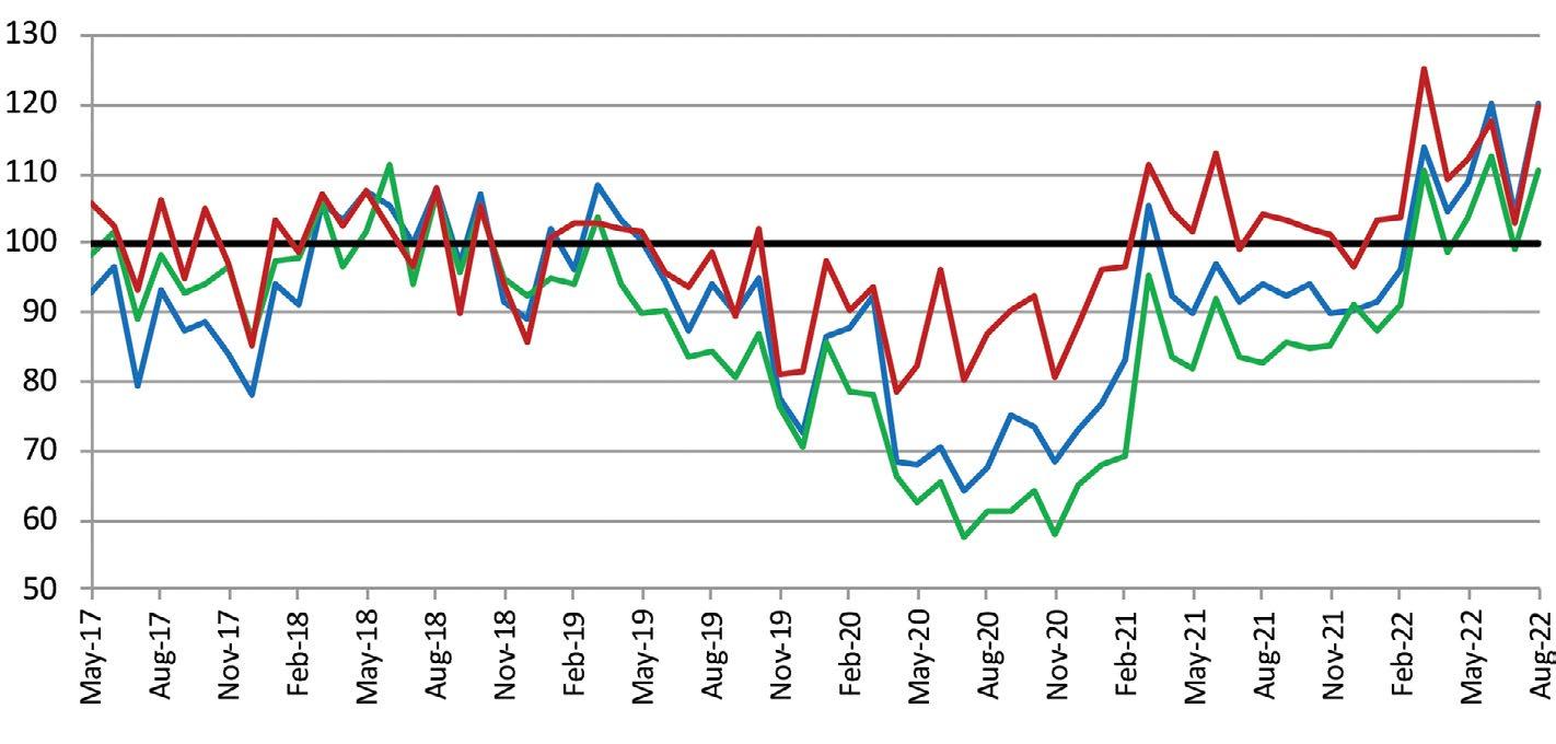
After dropping slightly in July, shipments of fluid power products increased in August, according to data from the National Fluid Power Association. NFPA’s raw index data shows pneumatic, mobile hydraulic, and industrial hydraulic shipments all grew in August when compared to July. The year-to-date change for total fluid power shipments in August was 16.4%. The 12-month moving average of shipments for pneumatics, hydraulics, and total fluid power continues to grow. The data is from fluid power manufacturers in NFPA’s Confidential Shipment Statistics (CSS) program.

Hydraulic and Pneumatic Shipments
Raw Index Data, Index: 2018=100
This graph of raw index data is generated by the total dollar volume reported to NFPA by CSS participants and compared to the average monthly dollar volume in 2018. For example, the August 2022 total dollar volume for pneumatic shipments is 119.8% of the average monthly dollar volume in 2018. (Base Year 2018 = 100)
SHIPMENTS
MONTH TOTAL FLUID POWER TOTAL HYD. TOTAL PNEU.
Jun 2022 15.5 18.1 7.6
Jul 2022 15.2 17.8 7.1
Aug 2022* 16.4 19.0 8.1
*Preliminary data subject to revision.
Shipments – Cumulative year‐to‐date % change (2022 vs. 2021)
The table above is expressed in terms of cumulative percent changes. These changes refer to the percent difference between the relevant cumulative total for 2022 and the total for the same months in 2021. For example, August 2022 pneumatic shipments figure of 8.1 means that for the calendar year through August 2022, pneumatic shipments increased 8.1% compared to the same time-period in 2021.
Pneumatic, Mobile and Industrial Hydraulic Orders 12/12 Ratio
Each point on this graph represents the most recent 12 months of orders compared to the previous 12 months of orders. Each point can be read as a percentage. For example, 125.0 (the August 2022 level of the industrial hydraulic series) indicates that industrial hydraulic orders received from September 2021 to August 2022 were 125.0 % of the orders received from September 2020 to August 2021. (Base Year 2018 =100)
Total ‐ Hydraulic and Pneumatic Shipments 12 Month Moving Average
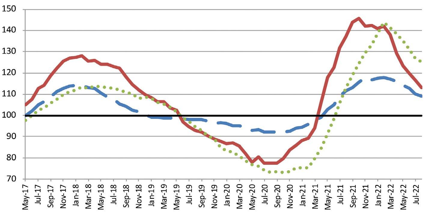
This graph of 12-month moving averages shows that in August 2022, total fluid power, total pneumatic, and total hydraulic all increased. (Base Year 2018 = 100)
12 NOVEMBER 2022 WWW.FLUIDPOWERJOURNAL.COM • WWW.IFPS.ORG
NFPA UPDATE
Newly Certified Professionals
August 2022
ACCREDITED INSTRUCTORS
David Rowe, Altec Industries
Seth Davis, Pueblo Community College
Kevin Lynk
CONNECTOR AND CONDUCTOR


Travis Barthalow, Manitowoc Crane Group
Joe Hege, Manitowoc Cranes
ELECTRONIC CONTROLS SPECIALIST




Andrew Patience
Evan Dimmerling
Erick Garza, HydraForce
Quinn Schmidt, HydraForce
Cole Yungerman, HydraForce
Orlando Arvelo
HYDRAULIC SPECIALIST
Andrew Blackstock
William Kapherr, Altec Industries
Tyler Miller
Jason Stewart
David Wyandt, Motion Industries Andrew Duncan, Altec Industries
MOBILE HYDRAULIC MECHANIC
Trevor Swanson, Altec Industries
Matt Barnes, Ameren Corporation
Jacob Cook, Ameren Corporation
Dale Hendricks, Ameren Corporation
Caleb Krotz, Ameren Corporation
Stephen Lindewirth, Ameren Corporation
Aaron Stengel, Ameren Corporation
Rolando Casas, AEP
William Bower Jr., Southern California Edison
Kyle Kemper, Altec Industries
Kyle Rush, Motion & Flow Control Products
Tyler Coots, Altec Industries
Matt Moreman, Altec Industries John Ronkainen, Altec Industries
Nicolas Heredia, Altec Industries
Juan Vega, Altec Industries
Bryce Trone, Altec Industries
PNEUMATIC SPECIALIST
Alana Torres Vidal, Norgren
Ryan Bumgarner, SMC Corporation of America
Gloriana Urdaneta Azuaje, IMI Precision Engineering
Bradley Wagner, Manitowoc Crane Group
Matthew Eckert, Gulf Controls Company
Joshua Pilkin, IMI-Norgren LLC
SPECIALIST
Holds HS and PS Certifications
Bradley Wagner, Manitowoc Crane Group Matthew Eckert, Gulf Controls Company
Mark Your Calendar
WEB SEMINAR: THE CONSTRUCTION, OPERATION, SIZING, AND APPLICATIONS OF USING ACCUMULATORS

Dec. 21, 12-1 p.m. ET
Presented by Medhat Khalil, CFPAI, CPFHS
IFPS SPRING MEETING
Feb. 27-March 2, 2023, New Orleans
IFPS ANNUAL MEETING AND HALL OF FAME AWARDS CEREMONY

Sept. 25-28, 2023, Milwaukee
For more information, visit www.ifps.org.
INTERNATIONAL FLUID POWER EXPOSITION
March 14-18, 2023, Las Vegas (Visit us at booth SL80126!)


IFPS SPRING 2024 MEETING
March 11-14, 2024, San Antonio, Texas
TRAINING
UPSKILL YOUR WORKFORCE!
direct, Industry
Hands-On Training
turnkey
WWW.IFPS.ORG • WWW.FLUIDPOWERJOURNAL.COM NOVEMBER 2022 13 CFCINDUSTRIALTRAINING.com 7042 Fairfield Business Drive Fairfield, Ohio 45014 +1 513.874.3225 info@cfcindustrialtraining.com
ONSITE
CFC provides
and/or Machine specific training to companies the world over. Electrical Techs & Engineers Hydraulic Techs & Engineers Pneumatic Techs & Engineers Our
Equipment is mobilized directly to your facility with Certified Instructors traveling on site. This
approach includes all books, materials, equipment, and travel arrangements. We have the capability to upskill your entire workforce NOW! Multicraft Techs & Engineers
IFPS UPDATE
IFPS Online Training Opportunities
IFPS has a range of online resources for professional study and training.
Interactive Hydraulic Specialist Study Manuals
Whether studying for the hydraulic specialist certification test, or you simply want to enhance your existing hydraulic skills in a convenient and flexible environment, the new interactive Hydraulic Specialist Study Manual can help. The cost is $349. Visit https://www.ifps.org/online-training to order.
Animated Hydraulic Circuits
Visually seeing a circuit perform along with a description of operation can increase the comprehension of a particular component’s operation and its function within the circuit.
These animated presentations can be used by:
• Anyone interested learning component function and circuit operation.
• Instructors to assist in hydraulic specialist certification review training.
• Individuals to enhance their preparation to take the hydraulic specialist certification test.
Online Hydraulic Safety Awareness Training
IFPS offers online self-paced hydraulic safety awareness training courses. They provide an awareness of hydraulic hazards in the workplace,
in-depth reviews of potential exposures to injury from hydraulic systems, and ways to reduce risk and eliminate hazards for workers, equipment, companies, and the environment.
IFPS offers four online hydraulic safety awareness training courses:
• Exposure Level
• High Risk Maintenance Level
• Hydraulic Safety in Construction
• Fluid Injection Awareness
Online Training
Each self-paced course delivers a broad-based understanding of the most important fluid power subject matter concepts. Courses begin with the basics: physics laws, systems basics and design, basic analysis, and basic components. The courses demonstrate how these systems apply to fluid power and how they interact with each other.
Each training course features 12 to 16 hours of trade-specific e-training that uses simulations, assessments, quizzes, tests, learning labs, and more.
Completing online training courses does not result in IFPS certification. However, completing courses better prepares you for certification tests.
Available online courses include:
• Mobile Hydraulics Course*
• Industrial Hydraulics Course **
• Industrial Mechanical Course *
• Mobile Electrical Course *
• Industrial Pneumatics Course *
• Industrial Electrical Course *
Air Compressors
Clean Dry Air Improves Performance...
Clean, Dry Compressed Air Starts with The Extractor/Dryer® Manufactured by LA-MAn Corporation

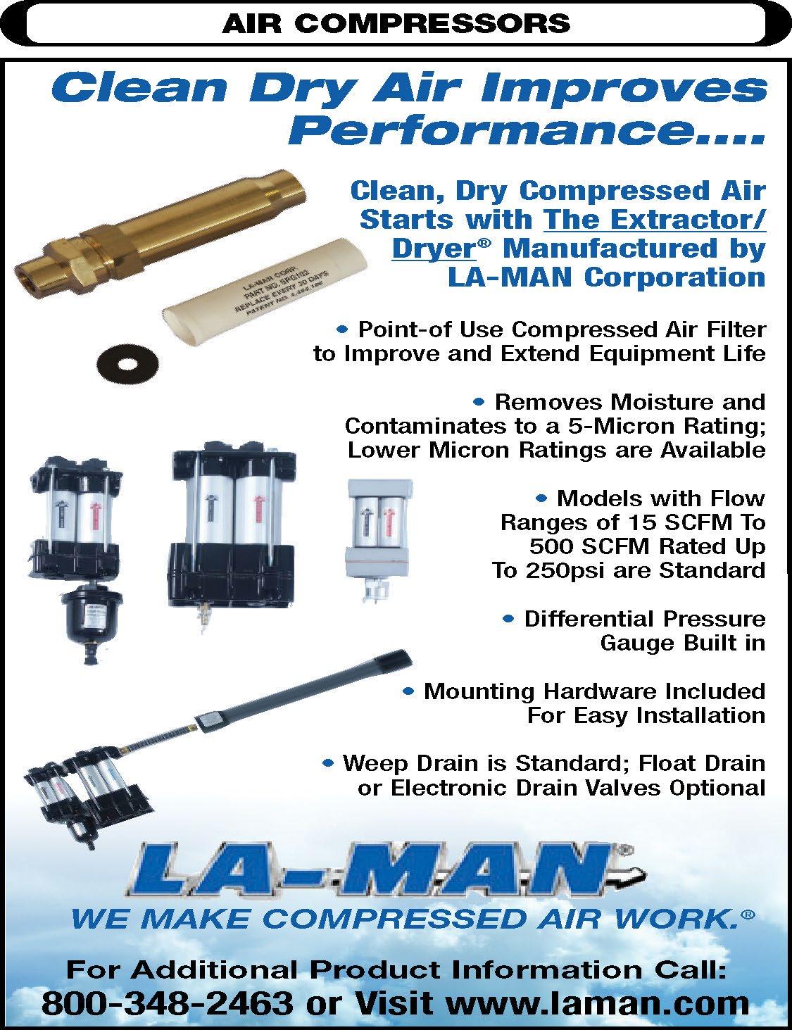


Point of Use Compressed Air Filter to Improve and Extend Equipment Life
Removes Moisture and Contaminates to a 5-Micron Rating: Lower Micron Ratings are Available

Models with Flow Ranges of 15 SCFM
500 SCFM Rated Up To 250psi are Standard
Differential Pressure Gauge Built in
• Electrical Theory *
• AC/DC Motors and Drives *
• Diesel Engines *
• PLC Fundamentals + *available in metric, ** available in metric, Span ish, and Spanish (metric), + available in Spanish
Online Certification Review Training
Here’s an excellent tool to prepare for IFPS certification at your own pace and from your own computer. You can enroll for this self-paced online certification review training through CFC Industrial Training’s Learning Management System. IFPS members receive a discount. Training is available for these certifications:
• Job Performance (for mechanic and technician certifications)
• Mobile Hydraulic Mechanic (writ ten test review)
Hardware
for Easy Installation
Drain is Standard; Float Drain
Electronic Drain
• Mobile Hydraulic Mechanic written and Job Performance (as a bundle)
• Connector and Conductor
Online Web Seminars
IFPS holds web seminars every month. View a list of archived webinars at www.ifps.org.
14 WWW.FLUIDPOWERJOURNAL.COM • WWW.IFPS.ORG
Cer tification Empowers Opportunity. IFPS UPDATE
•
•
•
to
•
• Mounting
Included
• Weep
or
Valves Optional
Revised Handbook Now Available
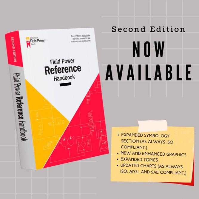
» A SECOND EDITION of the Fluid Power Reference Handbook is now available. Highlights of the second edition include:
• An expanded symbology section ISO 1219 compliant.
• New and enhanced graphics.
• Expanded topics.
• Updated charts that are ISO, ANSI, and SAE compliant.
The 388-page Fluid Power Reference Handbook is the gold standard on-the-job reference tool of choice for any fluid power professional. IFPS has sold over 2,000 copies since its first publication in 2020.
Soft-cover: Members - $74.95 | Retail - $125.95
Hard-cover: Members - $149.99 |Retail - $165.99
For more information and to purchase, visit www.ifps.org/training-resources-handbook.
IFPS Seeking Web Presenters
IFPS is looking for web presenters to conduct hour-long online presentations.
IFPS Names Pollander CEO
Donna Pollander, executive director of the International Fluid Power Society, has been promoted to CEO of the organization.
IFPS’s board of directors approved the move during its annual meeting in September. According to an IFPS press release, Pollander will continue to serve as key liaison to the board of directors and be responsible for dayto-day operations. She will continue to ensure the consistent achievement of IFPS’s mission and financial objectives, provide leadership in developing certification programs and other educational opportunities, and execute orga nizational and financial plans with the board of directors and staff.
Some of the advantages of participating include:
• You’ll receive recertification points.
• You’ll receive a free thank-you golf shirt.
• It's a great promotion for you and for your company.
• IFPS provides a template to use.
• You’ll be able to rehearse before going live.
If you are interested or would like more information, contact vpiro@ifps.org.
“IFPS is part of the fiber of who I am, and I am proud to see it flourishing,” Pollander said in the press release. “IFPS’s future is bright, and I am very excited to be at the helm of such an integral part of the fluid power industry!”
IFPS is a nonprofit 501(c)(3) professional organization of individuals dedicated to enhancing the quality of certifications, educational opportunities, technology evolution, and professionalism within the fluid power industry. IFPS was founded in Detroit in 1960 by a group of 30 profession als interested in supporting the future of the fluid power industry and the ever-chang ing technologies involved. Beginning with the first Fluid Power Hydraulic Specialist Certification in 1980, IFPS has become the recognized industry leader in fluid power and motion control certifications. Fifteen
“Donna was in reality performing the duties as CEO for quite a while,” Denis Poirier, IFPS board president, said in the press release. “So the board felt it was time to acknowledge her efforts.”
Pollander started her career in fluid power in 1995, working part time with the company that managed the Fluid Power Distributors Associ ation. She’s held various positions in the management company until her promotion to IFPS executive director in 2003. IFPS decided to hire the staff in 2014.

different certifications are currently offered, and two are in development. The certifications cover diverse job descriptions, including mechanic, technician, specialist, system designer, and engineer. To date, IFPS has issued over 34,000 certifications.
For more information, visit www.ifps.org.
WWW.IFPS.ORG • WWW.FLUIDPOWERJOURNAL.COM NOVEMBER 2022 15
IFPS UPDATE
Written Certification Test Locations
ALABAMA
Auburn, AL Birmingham, AL
Individuals wishing to take any IFPS written certification tests can select from convenient locations across the United States and Canada. IFPS is able to offer these locations through its affiliation with the Consortium of College Testing Centers provided by National College Testing Association.
Contact headquarters if you do not see a location near you. Every effort will be made to accommodate your needs.
If your test was postponed due to the pandemic, please contact headquarters so that we may reschedule.
Calera, AL Decatur, AL Huntsville, AL Jacksonville, AL Mobile, AL Montgomery, AL Normal, AL Tuscaloosa, AL
ALASKA Anchorage, AK Fairbanks, AK
ARIZONA
Flagstaff, AZ Glendale, AZ Mesa, AZ Phoenix, AZ Prescott, AZ Scottsdale, AZ Sierra Vista, AZ Tempe, AZ Thatcher, AZ Tucson, AZ Yuma, AZ
ARKANSAS
Bentonville, AR Hot Springs, AR Little Rock, AR
CALIFORNIA
Aptos, CA Arcata, CA Bakersfield, CA Dixon, CA Encinitas, CA Fresno, CA Irvine, CA Marysville, CA Riverside, CA Salinas, CA San Diego, CA San Jose, CA San Luis Obispo, CA Santa Ana, CA Santa Maria, CA Santa Rosa, CA Tustin, CA Yucaipa, CA
COLORADO Aurora, CO Boulder, CO Springs, CO Denver, CO Durango, CO Ft. Collins, CO Greeley, CO Lakewood, CO Littleton, CO Pueblo, CO
DELAWARE Dover, DE Georgetown, DE Newark, DE
Tallahassee, FL Tampa, FL West Palm Beach, FL Wildwood, FL Winter Haven, FL
GEORGIA
Albany, GA Athens, GA Atlanta, GA Carrollton, GA Columbus, GA Dahlonega, GA Dublin, GA Dunwoody, GA Forest Park, GA Lawrenceville, GA Morrow, GA Oakwood, GA Savannah, GA Statesboro, GA Tifton, GA Valdosta, GA
HAWAII
Laie, HI
IDAHO
Boise, ID Coeur d ‘Alene, ID Idaho Falls, ID Lewiston, ID Moscow, ID Nampa, ID Rexburg, ID Twin Falls, ID
ILLINOIS
Carbondale, IL Carterville, IL Champaign, IL Decatur, IL Edwardsville, IL Glen Ellyn, IL Joliet, IL Malta, IL Normal, IL Peoria, IL Schaumburg, IL Springfield, IL University Park, IL
INDIANA
Bloomington, IN Columbus, IN Evansville, IN Fort Wayne, IN Gary, IN Indianapolis, IN Kokomo, IN Lafayette, IN Lawrenceburg, IN Madison, IN Muncie, IN New Albany, IN Richmond, IN Sellersburg, IN South Bend, IN Terre Haute, IN
LOUISIANA
Bossier City, LA Lafayette, LA
Monroe, LA
Natchitoches, LA New Orleans, LA Shreveport, LA Thibodaux, LA
MARYLAND
Arnold, MD
Bel Air, MD
College Park, MD Frederick, MD Hagerstown, MD La Plata, MD Westminster, MD Woodlawn, MD Wye Mills, MD
MASSACHUSETTS
Boston, MA
Bridgewater, MA Danvers, MA Haverhill, MA Holyoke, MA Shrewsbury, MA
MICHIGAN
Ann Arbor, MI Big Rapids, MI Chesterfield, MI Dearborn, MI Dowagiac, MI East Lansing, MI Flint, MI
Grand Rapids, MI Kalamazoo, MI Lansing, MI Livonia, MI Mount Pleasant, MI Sault Ste. Marie, M Troy, MI University Center, MI Warren, MI
MINNESOTA Alexandria, MN Brooklyn Park, MN Duluth, MN Eden Prairie, MN Granite Falls, MN Mankato, MN
MISSISSIPPI Goodman, MS Jackson, MS Mississippi State, MS Raymond, MS University, MS
MISSOURI
NEW JERSEY

Branchburg, NJ Cherry Hill, NJ Lincroft, NJ Sewell, NJ Toms River, NJ West Windsor, NJ
NEW MEXICO
Albuquerque, NM Clovis, NM Farmington, NM Portales, NM Santa Fe, NM
NEW YORK Alfred, NY Brooklyn, NY Buffalo, NY Garden City, NY New York, NY Rochester, NY Syracuse, NY
NORTH CAROLINA Apex, NC Asheville, NC Boone, NC Charlotte, NC China Grove, NC Durham, NC Fayetteville, NC Greenville, NC Jamestown, NC Misenheimer, NC Mount Airy, NC Pembroke, NC Raleigh, NC Wilmington, NC
NORTH DAKOTA Bismarck, ND OHIO
Akron, OH Cincinnati, OH Cleveland, OH Columbus, OH Fairfield, OH Findlay, OH Kirtland, OH Lima, OH Maumee, OH Newark, OH North Royalton, OH Rio Grande, OH Toledo, OH Warren, OH Youngstown, OH
OKLAHOMA
SOUTH CAROLINA
Beaufort, SC Charleston, SC Columbia, SC Conway, SC
Graniteville, SC Greenville, SC Greenwood, SC Orangeburg, SC Rock Hill, SC Spartanburg, SC
TENNESSEE
Blountville, TN Clarksville, TN Collegedale, TN
Gallatin, TN Johnson City, TN Knoxville, TN Memphis, TN Morristown, TN Murfreesboro, TN Nashville, TN
TEXAS Abilene, TX Arlington, TX Austin, TX Beaumont, TX Brownsville, TX Commerce, TX Corpus Christi, TX Dallas, TX Denison, TX El Paso, TX Houston, TX Huntsville, TX Laredo, TX Lubbock, TX Lufkin, TX Mesquite, TX San Antonio, TX Victoria, TX Waxahachie, TX Weatherford, TX Wichita Falls, TX
UTAH
Cedar City, UT Kaysville, UT Logan, UT Ogden, UT Orem, UT Salt Lake City, UT
WYOMING
Casper, WY Laramie, WY Torrington, WY
CANADA
ALBERTA Calgary, AB Edmonton, AB Fort McMurray, AB Lethbridge, AB Lloydminster, AB Olds, AB Red Deer, AB
BRITISH
COLUMBIA
Abbotsford, BC Burnaby, BC Castlegar, BC Delta, BC Kamloops, BC Nanaimo, BC Prince George, BC Richmond, BC Surrey, BC Vancouver, BC Victoria, BC
MANITOBA Brandon, MB Winnipeg, MB
NEW BRUNSWICK Bathurst, NB Moncton, NB
NEWFOUNDLAND AND LABRADOR St. John’s, NL
NOVA SCOTIA Halifax, NS
ONTARIO
JOB PERFORMANCE TEST LOCATIONS
Arizona California Colorado Florida Georgia Maine Michigan Minnesota Montana New Jersey
Nova Scotia Pennsylvania Texas Washington Wyoming Western Australia
FLORIDA
Avon Park, FL Boca Raton, FL Cocoa, FL Davie, FL Daytona Beach, FL Fort Pierce, FL Ft. Myers, FL Gainesville, FL Jacksonville, FL Miami Gardens, FL Milton, FL New Port Richey, FL Ocala, FL Orlando, FL Panama City, FL Pembroke Pines, FL Pensacola, FL Plant City, FL Riviera Beach, FL Sanford, FL
IOWA
Ames, IA Cedar Rapids, IA Iowa City, IA Ottumwa, IA Sioux City, IA Waterloo, IA
KANSAS
Kansas City, KS Lawrence, KS Manhattan, KS Wichita, KS
KENTUCKY
Ashland, KY Bowling Green, KY Erlanger, KY Highland Heights, KY Louisville, KY Morehead, KY
Berkley, MO Cape Girardeau, MO Columbia, MO Cottleville, MO Joplin, MO Kansas City, MO Kirksville, MO Park Hills, MO Poplar Bluff, MO Rolla, MO Sedalia, MO Springfield, MO St. Joseph, MO St. Louis, MO Warrensburg, MO
MONTANA Bozeman, MT Missoula, MT
NEBRASKA Lincoln, NE North Platte, NE Omaha, NE
NEVADA Henderson, NV Las Vegas, NV North Las Vegas, NV Winnemucca, NV
Altus, OK Bethany, OK Edmond, OK Norman, OK Oklahoma City, OK Tonkawa, OK Tulsa, OK
OREGON Bend, OR Coos Bay, OR Eugene, OR Gresham, OR Klamath Falls, OR Medford, OR Oregon City, OR Portland, OR White City, OR
PENNSYLVANIA Bloomsburg, PA Blue Bell, PA Gettysburg, PA Harrisburg, PA Lancaster, PA Newtown, PA Philadelphia, PA Pittsburgh, PA Wilkes-Barre, PA York, PA
VIRGINIA Daleville, VA Fredericksburg, VA Lynchburg, VA Manassas, VA Norfolk, VA Roanoke, VA Salem, VA Staunton, VA Suffolk, VA Virginia Beach, VA Wytheville, VA
WASHINGTON Auburn, WA Bellingham, WA Bremerton, WA Ellensburg, WA Ephrata, WA Olympia, WA Pasco, WA Rockingham, WA Seattle, WA Shoreline, WA Spokane, WA
WEST VIRGINIA Ona, WV
WISCONSIN La Crosse, WI Milwaukee, WI Mukwonago, WI
Brockville, ON Hamilton, ON London, ON Milton, ON Mississauga, ON Niagara-on-the-Lake, ON North Bay, ON North York, ON Ottawa, ON Toronto, ON Welland, ON Windsor, ON
QUEBEC
Côte Saint-Luc, QB Montreal, QB
SASKATCHEWAN Melfort, SK Moose Jaw, SK Nipawin, SK Prince Albert, SK Saskatoon, SK
YUKON TERRITORY Whitehorse, YU
UNITED KINGDOM Elgin, UK
GHAZNI Kingdom of Bahrain, GHA Thomasville, GHA EGYPT Cairo, EG
JORDAN Amman, JOR
NEW ZEALAND Taradale, NZ
16 NOVEMBER 2022 WWW.FLUIDPOWERJOURNAL.COM • WWW.IFPS.ORG IFPS UPDATE
TENTATIVE TESTING DATES FOR ALL LOCATIONS: December 2022 Tuesday 12/6 • Thursday 12/15 January 2023 Tuesday 1/10 • Thursday 1/26 February 2023 Tuesday 2/7 • Thursday 2/23 March 2023 Tuesday 3/7 • Tuesday 3/28 Cer tification Empowers Opportunity.
IFPS CERTIFICATIONS
CFPAI
Certified Fluid Power Accredited Instructor
CFPAJPP
Certified Fluid Power Authorized Job Performance Proctor
CFPAJPPCC
Certified Fluid Power Authorized Job Performance Proctor Connector & Conductor
CFPE
Certified Fluid Power Engineer
CFPS
Certified Fluid Power Specialist (Must Obtain CFPHS & CFPPS)
CFPHS
Certified Fluid Power Hydraulic Specialist
CFPPS
Certified Fluid Power Pneumatic Specialist
CFPECS
Certified Fluid Power Electronic Controls Specialist
CFPMT
Certified Fluid Power Master Technician (Must Obtain CFPIHT, CFPMHT, & CFPPT)
CFPIHT
Certified Fluid Power Industrial Hydraulic Technician
CFPMHT
Certified Fluid Power Mobile Hydraulic Technician
CFPPT Certified Fluid Power Pneumatic Technician
CFPMM
Certified Fluid Power Master Mechanic (Must Obtain CFPIHM, CFPMHM, & CFPPM)
CFPIHM
Certified Fluid Power Industrial Hydraulic Mechanic
CFPMHM
Certified Fluid Power Mobile Hydraulic Mechanic
CFPPM
Certified Fluid Power Pneumatic Mechanic
CFPMIH
Certified Fluid Power Master of Industrial Hydraulics (Must Obtain CFPIHM, CFPIHT, & CFPCC)
CFPMMH
Certified Fluid Power Master of Mobile Hydraulics (Must Obtain CFPMHM, CFPMHT, & CFPCC)
CFPMIP Certified Fluid Power Master of Industrial Pneumatics (Must Obtain CFPPM, CFPPT, & CFPCC)
CFPCC
Certified Fluid Power Connector & Conductor
CFPSD
Fluid Power System Designer
CFPMEC (In Development)
Mobile Electronic Controls
CFPIEC (In Development) Industrial Electronic Controls
Tentative Certification Review Training
IFPS offers onsite review training for small groups of at least 10 persons. An IFPS accredited instructor visits your company to conduct the review. Contact kpollander@ifps.org for details of the scheduled onsite reviews listed below.
HYDRAULIC SPECIALIST
Onsite review training for small groups. Contact IFPS for details.
Nov. 28-Dec. 1, Fairfield, OH. CFC Industrial Training. Written test: Dec. 2. Contact info@cfcindustrialtraining.com for more information and to register. May 1-3, 2023, Mukwonago, WI, MSOE. Written test: May 4, 2023
PNEUMATIC SPECIALIST
Onsite review training for small groups. Contact IFPS for details. Dec. 12-16, Fairfield, OH, CFC Industrial Training. Written test: Dec. 16.
CONNECTOR & CONDUCTOR
Onsite review training for small groups. Contact IFPS for details Nov. 15-16, Fairfield, OH, CFC Industrial Training. Written and JP test: Nov. 17.
ELECTRONIC CONTROLS SPECIALIST
Onsite review training for small groups. Contact IFPS for details.
INDUSTRIAL HYDRAULIC MECHANIC
Onsite review training for small groups. Contact IFPS for details.
INDUSTRIAL HYDRAULIC TECHNICIAN
Onsite review training for small groups. Contact IFPS for details.
MOBILE HYDRAULIC TECHNICIAN
Onsite review training for small groups. Contact IFPS for details. Call CFC Industrial Training, Fairfield, OH, for dates: (513) 874-3225.
PNEUMATIC TECHNICIAN and PNEUMATIC MECHANIC Onsite review training for small groups – contact IFPS for details Call CFC Industrial Training, Fairfield, OH, for dates: (513) 874-3225.
JOB PERFORMANCE TRAINING
Online Job Performance review. CFC Industrial Training offers online JP Reviews that include stations 1-6 of the IFPS mechanic and technician job performance tests. Members may e-mail askus@IFPS. org for a 20% coupon code off the list price. Test fees are not included. For more information, contact info@cfcindustrialtraining.com.
LIVE DISTANCE LEARNING JOB PERFORMANCE STATION REVIEW
For more information, contact info@cfcindustrialtraining.com.
WWW.IFPS.ORG • WWW.FLUIDPOWERJOURNAL.COM NOVEMBER 2022 17 AVAILABLE
IFPS UPDATE
All Around the World Circular Sustainability for Fluid Power
By Michael Cook, Global Segment Director for Off-Highway & Segment Manager Fluid Power in the Americas, Trelleborg Sealing Solutions
In today’s environmental and economic landscape, it is critical for fluid power component manufacturers and seal suppliers to incorpo rate sustainable methods into design, manufacturing, and production practices through design thinking for circularity and circular products.
For a long time, our economy had been a linear concept. This meant taking the needed resources, making a product, using it, and then, at the end of its life, sending it to a landfill or to be recycled. Until recently, sustainability focused on recycling and energy usage.
At the forefront of sustainability is the concept of product circularity and a circular economy. Circularity is more than developing a product that can be recycled; it is about designing extended value into a product, for the customer, for their customer, and for the first, second, and even third users of the product. It is not a step-by-step linear process with a clear end but a continuous cycle.
The circular economy
Seal suppliers and OEMs should consider the circular economy in the design phase of their products, materials, and solutions instead of using the traditional linear economy approach to manufacturing – taking a raw material, making it into something, and at the end of its life disposing of it. Creating circular products that last longer and use less energy, can be repaired, refurbished, or recycled, and have a useful second life supports the circular economy and sustainability. In a circular economy, OEMs aim to reduce waste through the reuse, recycling, and repurposing of a product. Leading component manufacturers do this through design thinking for circularity.
CIRCULAR ECONOMY
As opposed to a disposable design that has no consideration of what happens to the product at the end of its life, design thinking for circu larity shifts the way products are developed. It is thinking about product design from the very start, with a desire to develop solutions that are part of the circular economy and designed with the environment and sustainability in mind.
Design thinking for circularity at Trelleborg Sealing Solutions is not about designing a product for recycling; it’s about designing seals that last longer, use less energy, and support easy repair and replacement.
It’s critical that seal manufacturers create high-performance seals with a long life so that customers replace them less often, resulting in less waste, reduced raw material use, and a greater return on investment.
High performance starts at the design phase. Seal manufacturers like Trelleborg model seal performance through finite element analysis and simulations across a range of application conditions and materials. This allows manufacturers to modify designs prior to testing, reducing the number of prototype loops, lowering development costs, reducing material waste, and speeding up the time to market. The extensive testing ensures seals perform as expected in an application.
Design for the environment
When possible, raw materials should come from sustainable and renewable sources. Regrinding production waste into a material blend for noncritical components such as wipers and wear rings gives this material a second life, reducing material sent to landfills.
Manufacture
Raw Material
Sustainable sourcing from renewable sources is the best-case scenario.
Recycle
Recycling is a great way to reduce dependence on raw materials. Recycled material becomes the new raw material.
Minimal Waste

Eco-friendly compostable materials.
Minimizing energy usage, minimizing waste, and maintaining quality are core to a sustainable future.
Reuse
Equipment and products are too often replaced long before the useful life has expired. Use it longer, sell it, donate it.
Remanufacture
Make it new again significantly reduces waste and carbon usage compared to making it new from scratch.
18 NOVEMBER 2022 WWW.FLUIDPOWERJOURNAL.COM • WWW.IFPS.ORG
Circular Products
By creating virtually leak-free seal designs, fluid power seal manufac turers minimize the risk of contamination to ground and water resources, protecting the environment from contaminants.
The extended product life of seals has a clear impact on sustainability. Fewer parts to replace means using fewer consumables and raw materials. The transport and logistics involved in moving parts and people to remote locations also have a massive impact on the environment. Extending product life reduces CO2 emissions in the supply chain.
When seal manufacturers provide robust lubrication management programs and technology, it reduces friction, wear, and heat generation in linear tandem sealing applications by allowing just the right amount of fluid film to reach the secondary seal and prevent dry running conditions. This reduces the energy needed to power the system and can support the downsizing of drive components, in turn reducing the overall amount of energy the equipment uses.
In rotary applications, Trelleborg uses Turcon Varilip PDR, a single-acting low friction seal with no stick-slip. The seal provides long-last ing seal efficiency and can withstand dry running conditions. When compared to a standard radial oil seal, the low friction characteristics mean the seal uses less energy and lowers the risk of environmental con tamination as a result of premature failure.
Modularity
Utilizing industry-standard design profiles and sizes ensures that designers and end users can easily specify sealing components, allowing the reuse of hardware designs. Standardization supports ease of repair, refurbishment, and reuse with readily available replacement parts, to give the hardware a second or third life.
During the design phase of a seal, seal manufacturers work with cus tomers to design solutions that can be easily disassembled to enable repair of parts. Seals that are easy to remove and replace minimize damage to equipment and reduce downtime.
The less material we put into landfills, the better. Methane gas that releases as waste decomposes in landfills creates a greenhouse gas that contributes to global warming and climate change.
When seals for fluid power applications are designed to last as long as possible, it reduces the need for replacement parts and the waste that gets placed in landfills. •
FACTS ABOUT THE CIRCULAR ECONOMY
The earth takes almost 1.5 years to regenerate what we use in a year.
After burning, 80% of waste from consumer goods goes to a landfill because of poor design or lack of end-of-life collection options.
Over 80% of a product’s environmental impact is determined at the design stage.
Currently, only 9% of our world economy is circular.
Sixty to 70% of the world’s ecosystems are degrading faster than they can recover.
We recycle less than 20% of electronic waste.
Recycling electronics uses less energy in production and conserves resources like copper and aluminum.
TRELLEBORG CIRCULAR PRODUCT DESIGNS
Here are two examples of circular product designs from Trelleborg.
Lightweight advanced composite materials. Trelleborg’s Automated Fiber Placement (AFP) technology is part of a special continuous-fiber manufacturing process that produces strong, lightweight components for a wide range of applications. This technology uses thermoplastic composite materials that are recyclable and suitable for repurposing at the end of life, unlike traditional thermoset composites.
Organically sourced materials. The development of bio-friendly materials using renewable plant-based compounds such as sugar cane and natural oils is something we are looking to explore in the future. These materials could allow Trelleborg to create sealing solutions that not only provide high-performance sealing with a long life but also use less energy and have a significantly reduced carbon footprint during manufacturing.

WWW.IFPS.ORG • WWW.FLUIDPOWERJOURNAL.COM NOVEMBER 2022 19
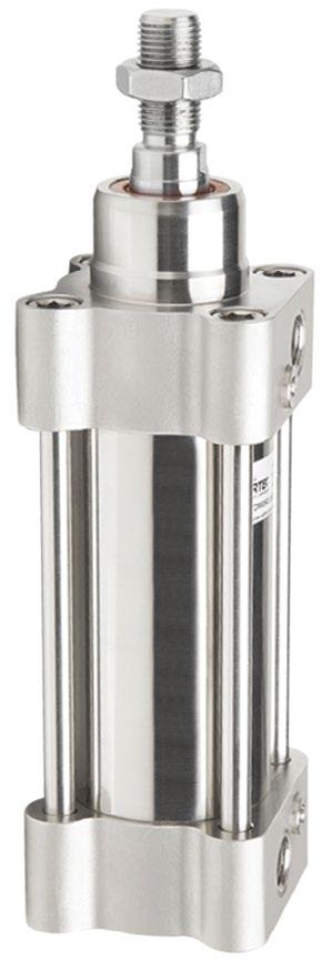
New Partnership Makes for Easier Access to ISO Pneumatic Rod Cylinders

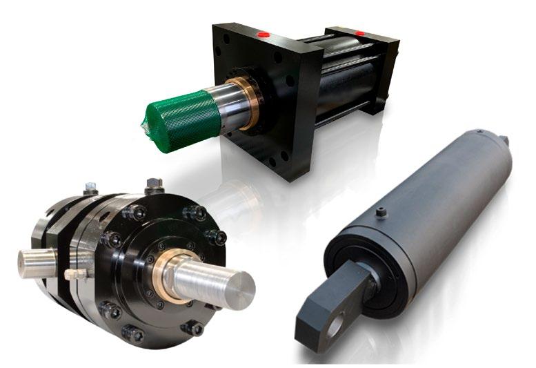
Don’t Compromise – that hydraulic flange you want maybe at MAIN
J518 Code
DIN,
flange

and
6162, ISO 6164, and specials with
butt-weld, ORB, BSPP, etc.; all geometries, flange
in carbon, stainless,
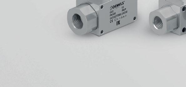
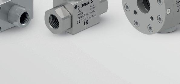
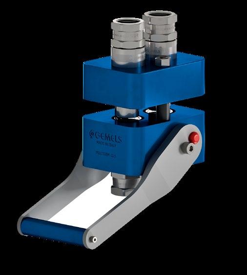
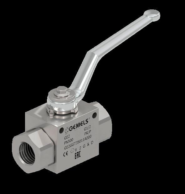
GEMELS IS THE WORLD'S LEADING

OF HIGH PRESSURE VALVES & QUICK COUPLINGS.



Contact us to showcase your products and services in the Product Spotlight. This special section is a high-profile area offering product-specific advertising. Visit www.fluidpowerjournal.com for more information or to view our media guide. SPECIAL AD SECTION WWW.IFPS.ORG • WWW.FLUIDPOWERJOURNAL.COM NOVEMBER 2022 21 Go ahead. Push me. Ordinary heavy duty not heavy enough? Heavy-Duty Mill Cylinders for: • Induction-Hardened, Chrome-Plated Rods • Heavy Wall Tubing • Replaceable Glands & Retainer Rings • High-Load Piston Design Think indestructible and call Yates. www.yatesind.com Yates Industries (HQ) 586.778.7680 Yates Cylinders Alabama 256.351.8081 Yates Cylinders Georgia 678.355.2240 Yates Cylinders Ohio 513.217.6777
MAIN stocks 10,000+ hydraulic flanges and manufactures components in 4-7 days in the USA. SAE
61
J518 Code 62, JIS,
ISO
socket-weld,
heads,
adapters;
cupro-nickel, ductile, aluminum, etc. Sixty years’ experience plus SAE and ISO technical committee experience. MAIN Manufacturing Products, Inc. 800.521.7918 https://mainmanufacturing.com/block-categories
MANUFACTURER
GEMELS NORTH AMERICA INC. northamerica@gemels.com gemels.com
W.C. Branham teams up with Artec SRL in the U.S. and Canada. Artec is a leading 40-year Italian rod cylinder manufacturer with ISO9001:2015 certification. Cylinders are their passion! 715.426.2000 AskWCB@WCBranham.com www.WCBranham.com High Quality Art On The Inside. Standard and Stainless Steel Cylinders ISO 6432 Micro Round | ISO 15552 ISO 21287 | UNITOP | Compact | Guided Compact | Short Stroke | Cartridge We at Branham Listen, Let Us Help You Today
www.flangelock.com
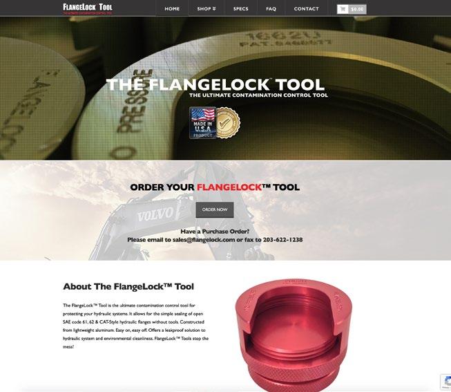
The FlangeLock™ Tool is the ultimate contamination control tool for protecting your hydraulic systems. It allows for the simple sealing of open SAE code 61, 62 & CAT-Style hydraulic flanges without tools. Constructed from lightweight aluminum. Easy on, easy off. Offers a leakproof solution to hydraulic system and environmental cleanliness. FlangeLock™ Tools stop the mess!
www.mainmanufacturing.com



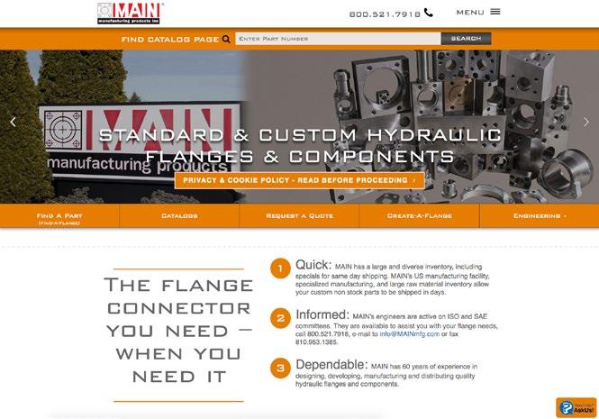
Main's website provides quick access to the 120 page catalog that includes popular styles of MAIN Manufacturing’s extensive offering of carbon and stainless Hydraulic Flanges and Components – ready for immediate shipment. Metric ordering information, weld specs, and dimensional information included. The “Quick Reference Guide” helps specify less popular items often stocked or quickly manufactured (generally 3-4 days) at our US plant. “Create-AFlange” offers more parts than the catalog — by picture. If it’s not here, or for questions, E-mails may be sent to get your answer quickly.
Have a Purchase Order? Please email to sales@flangelock.com or fax to 203-622-1238
Corporation is a leading manufacturer of compressed air filtration products. With over 30 years of experience, we truly understand the importance of protecting valuable machinery, tools, and finished products from dirty, wet, contaminated air. La-Man’s line of products include the patented Extractor Dryer, .01 micron filter, as well as, LA-MAN-Air Breathing Systems™, SuperStar™ Membrane Dryers, and the Refrigerated Extractor/Dryer.
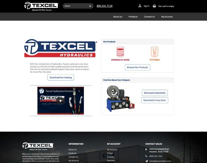
At Texcel, our cutting-edge line of hydraulic hose and fittings is not just a product division. It’s a promise of superior service, quality, technical support and availability. We’ve built our company on impeccable customer service. Let us know how we can make a difference for your business. 4444 Homestead Road • Houston, Texas 77028 (800) 231-7116 • sales@texcelrubber.com


22 NOVEMBER 2022 WWW.FLUIDPOWERJOURNAL.COM • WWW.IFPS.ORG SPECIAL AD SECTION Web MARKETPLACE
www.texcelhydraulics.com
1-800-521-7918 info@mainmfg.com www.laman.com La-Man
PO BOX 328 • Mazeppa, MN 55956 800-348-2463
COMPONENT SHOWCASE
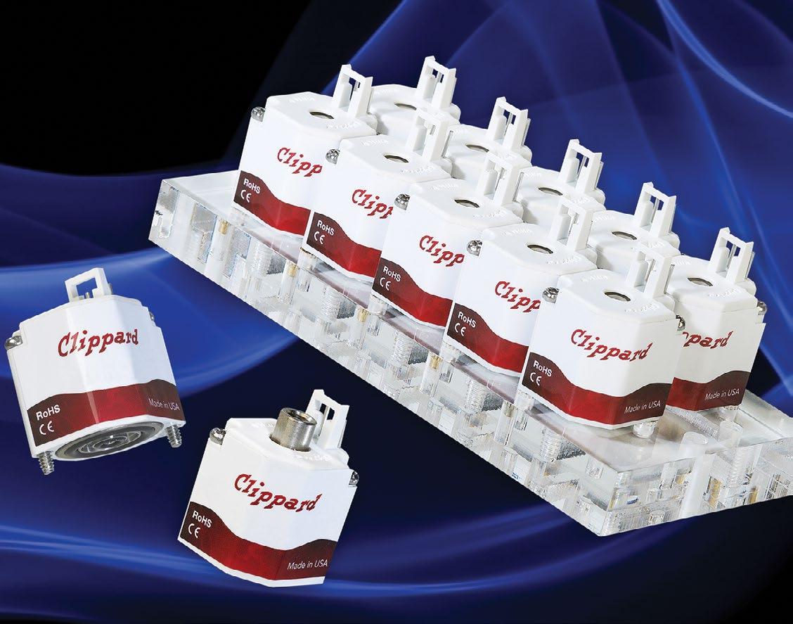
ES SERIES MINIATURE ELECTRONIC VALVES
Spider technology is renowned worldwide for exceptional leak resistance and long life. Clippard developed, patented and perfected this spider technology. Ideal applications have exceeded 1,000,000,000 cycles with this technology which utilizes one moving part that travels a mere 0.007” during operation. This single moving part with a short stroke enables the ES series to operate with exceptional reliability.
The ES series features large cross sectional o-rings, minimal leak points, and proven poppet designs. All mounting hardware is outside of the flow path for the ES, and no internal parts are threaded during assembly to reduce the possibility of contamination. The ES has the best performance-to-price ratio for low leak valves.
The compact footprint coupled with the long life, and exceptional leak resistance make the ES line suited to improve reliability in a wide range of applications including biomedical, dental, test equipment, oxygen control, textile, packaging, pressure control, automation and portable systems.
Over 1 billion cycles (under ideal conditions)
0.01 sccm leak rate
No threads in flow path
Fast response - 5 to 10 ms (nominal)
Close mounting - 7/8” on center.
Overall height less than 1”
No anaerobic sealant
Ideal for ultra-low leak applications
Made in USA
MINIATURE, DOUBLE ACTING, PNEUMATIC ACTUATORS
Small solutions to big problems. We carry the smallest pneumatic double acting actuator on the market.
Our miniature pneumatic actuators are manufactured to tight tolerances with premium quality and variations for travel, mounting, porting, and piston rods. The components are hard anodized aluminum with other materials available upon request. OD sizes from 1″ 2.50″and up to 2″ of travel is standard in 1/8″ increments.
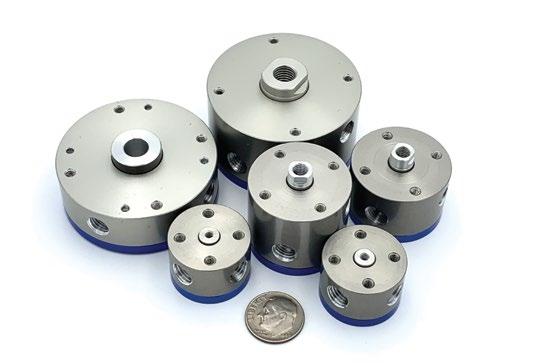

Miniature pneumatic actuators are often used in testing or production of; electronic components, medical devices, and high-end composite materials.
AUTOMATIC (RETURN) VACUUM CYLINDER
Pick up with ease!
Our automatic vacuum cylinders are non-rotating with a stable z axis actuation and automatic stroke compensation. The cylinder piston extends when vacuum is applied, and it automatically retracts when the rod end is sealed against the surface of the load. When vacuum is turned off, the load is released.
Be free of maintenance and lubrication through our hard anodize and Teflon coating on materials. Say yes to fast production and have our vacuum cylinders speed things up for you with rapid cycle rates.

WWW.IFPS.ORG • WWW.FLUIDPOWERJOURNAL.COM NOVEMBER 2022 23 SPECIAL AD SECTION
Mack Automation LLC • www.mackcorp.com • 928-526-1120 • info@mackcorp.com
CHECKED
CHECKED Avoiding Hydraulic Hose Disasters
By Mike Rutan, Product Development Manager, PIRTEK USA
CHECKED CHECKED
For essential businesses everywhere, equipment is their lifeline. If one piece isn’t working, it can put projects on hold and set your whole business back. Hydraulic hoses are a crucial equipment component in industries such as construction, engineering, manufacturing, agriculture, transportation, logistics, pharmaceuticals, rail, and automotive.
If something happens to a hydraulic hose, quick replacement is of the utmost importance. Luckily, there are preventative steps businesses can take to protect their equipment, operations, and company as a whole.

There are many reasons a hose fails. The most common one is simply old age. The life clock of a hydraulic hose starts ticking even before the hose is assembled, installed, and put into service. Like many products, hydraulic hoses have a “best before” date. As that date approaches, hoses become more susceptible to breakage. Environmental factors like temperature, humidity, and exposure to UV and ozone can alter the life expectancy of a hydraulic hose, as can storage methods. Additionally, some hoses are built to withstand extremely high temperatures, but when exposed to temperatures higher than what they’re made for, they can quickly become compromised.
Another reason hoses may fail is due to abrasions. Hoses that constantly rub against other machine parts compromise the outer cover, exposing the reinforcement layer to elements that can weaken the steel, reducing its ability to withstand pressures. Hoses sometimes come into contact with chemicals that can erode their structure.
How your hoses are secured can make a big difference when it comes to lifespan. Clamps often secure the hose in place, aid in proper flexion, and protect it from rubbing on adjacent parts. If clamps are missing or broken, it can drastically reduce the life expectancy of the hose.
Finally, many components break due to extreme amounts of pressure. Each hose is graded for how much pressure it can sustain. Even though hydraulic hoses have a 4:1 safety factor (burst pressure is four times the working pressure), significant pressure spikes can cause a hose to fail prematurely. If you install a hose that isn’t built to withstand the machine’s pressure requirements, it’s only a matter of time before you need to replace it.
Preventative maintenance
It has been said that an ounce of prevention is worth a pound of cure. This is never truer than when dealing with hydraulic and industrial equipment maintenance. In an environment with a high demand for employees and a short supply of people power, it is critical to maximize the efficiency of your human resources. Sending employees home or having employees reassigned to less productive work because of unplanned equipment down time is just one of the many costs associated with hydraulic hose failures.
Running your systems without regularly checking and performing maintenance is risky. Think of your car. What would happen if you went a year or more without an oil change, tire rotation, or a scheduled inspec tion when the “check engine” light is on?
Prevention can also help you avoid other costs associated with unex pected equipment failures, including:
• Lost productivity potentially resulting in lost revenue.
• Environmental spill clean-up, contamination removal, and revitalization (such as replacing sod).
• Potential fines for late project completion, which are common in the construction industry.
• Damage to nearby sensitive equipment, such as computers and other technology.
• Damage to products from oil spraying onto assembly lines.
• Legal expenses if an employee is injured due to an equipment failure on a job site.
• Hydraulic hose failures can cause other failures in the system’s pumps or valves.
Inspecting the hydraulic hose before putting it into service is imperative. Often, covers on the equipment need to be removed to visually inspect the hoses hidden inside the machine. On skid steer loaders, the rollover protection system needs to be removed or raised regularly to access the hoses on the pump, valves, drive motors, and so on. I have occasionally raised the rollover protection system on an older piece of equipment only to see that I am the first person in over a decade to have done so.
On excavators, the drive motors to the tracks are behind plates. I have removed the plates and found the entire compartment completely packed with sand, dirt, silt, and years of sediment that corroded the fittings. Excavators are sometimes used for dredging ponds and waterways, and the water can be very corrosive when tracks are submerged.
Another preventative measure is knowing when to replace hoses. I have replaced multiple hoses on a piece of equipment because the customer declined my recommendation to replace those hoses on my initial service visit. Instead, he only wanted the failed hose replaced.
I have also replaced hoses on an interstate highway where the tow truck owner not only had to pay for the replacement of the failed hose but also for spill cleanup and remediation, which cost thousands of dollars.
The best way to ensure that a system will last its full lifespan is to take care of it. Some modern hydraulic hoses can last one million impulse cycles when managed correctly.
Protecting workers
One reason to keep up with the maintenance of your hydraulic hoses is to prevent work-related injuries. Your equipment is key to making your company a safe place to work, and the failure of hydraulic hoses can result in several hazardous scenarios.
For example, when fluid at high pressure exits through a pinhole in a hose, it can cause a fluid injection injury to an employee. Fluid can cut through clothing and skin, enter the body and potentially cause a dangerous reaction or infection. For hydraulic hoses operating at high temperatures, fluid leakage can cause severe burns.
24 NOVEMBER 2022 WWW.FLUIDPOWERJOURNAL.COM • WWW.IFPS.ORG
CHECKED
Meanwhile, faulty hydraulic hoses can cover a surface in oil, causing the most common types of workplace injuries: slips and falls. Depending on the work environment, hydraulic fluid can be flammable or even explosive, enhancing the risk of fire if a hose fails.
Similarly, if a hose holding a mechanical load in the air fails, it can cause mechanical movement of the equipment, potentially resulting in serious injury to workers under or around the equipment.
Of course, if one part of a system fails, it can damage other components. If a hose failure is not discovered and mitigated right away, the whole machine can malfunction, posing a significant financial burden. You may also lose precious time waiting for new equipment to be delivered or installed.
Your business itself is also a machine. If your equipment is compro mised, you’ll be forced to shut down operations until you can repair it. Just because emergency hose replacement is available around the clock doesn’t mean you can wait until the last minute to inspect your hydraulic hoses. Waiting will almost guarantee that your business may end up closed for repairs and leave your projects in a precarious position.
Not only can faulty hydraulic hoses be dangerous for your people and machinery, they can also pose a hazard to the environment. A compro mised hose increases the potential for oil spills and other occurrences.
Keeping up with hose maintenance can prevent a company from damaging ecosystems and putting wildlife and fellow humans at risk.
In today’s day and age, we have a lot of information about the greater impact of industrial activities on our environment. Hydraulic hose main tenance can help preserve the health and well-being of residents, wildlife, groundwater, and the area around the recovery site.
From a professional perspective, environmental damage also equates to poor social responsibility, bad press, fines, and major cleanup costs. Even if you have budgeted for these scenarios, avoiding them at all costs is better. If your company has experienced poor hydraulic hose mainte nance that led to environmental hazards, this negative reputation can follow your business in future projects and jobs.
Maintaining hydraulic hoses
There are a few essential steps to keeping up with hose maintenance. First, look at the hose’s manufacturing date, which is typically printed on its outer cover. The age of the hose tells you if it needs to be inspected further.
Keep a record of when each hose is put into service. Hose assemblies have a predetermined life expectancy and should be replaced before their expected expiration.
Track when specific hoses are removed from service. This establishes a standard replacement interval for each machine, averting future hose failures. Finally, tagging hoses during installation helps signal when a hose needs replacement.
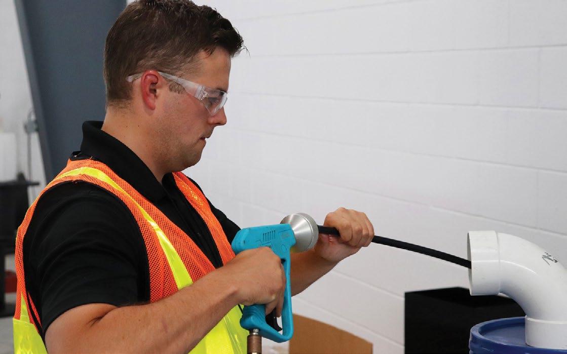
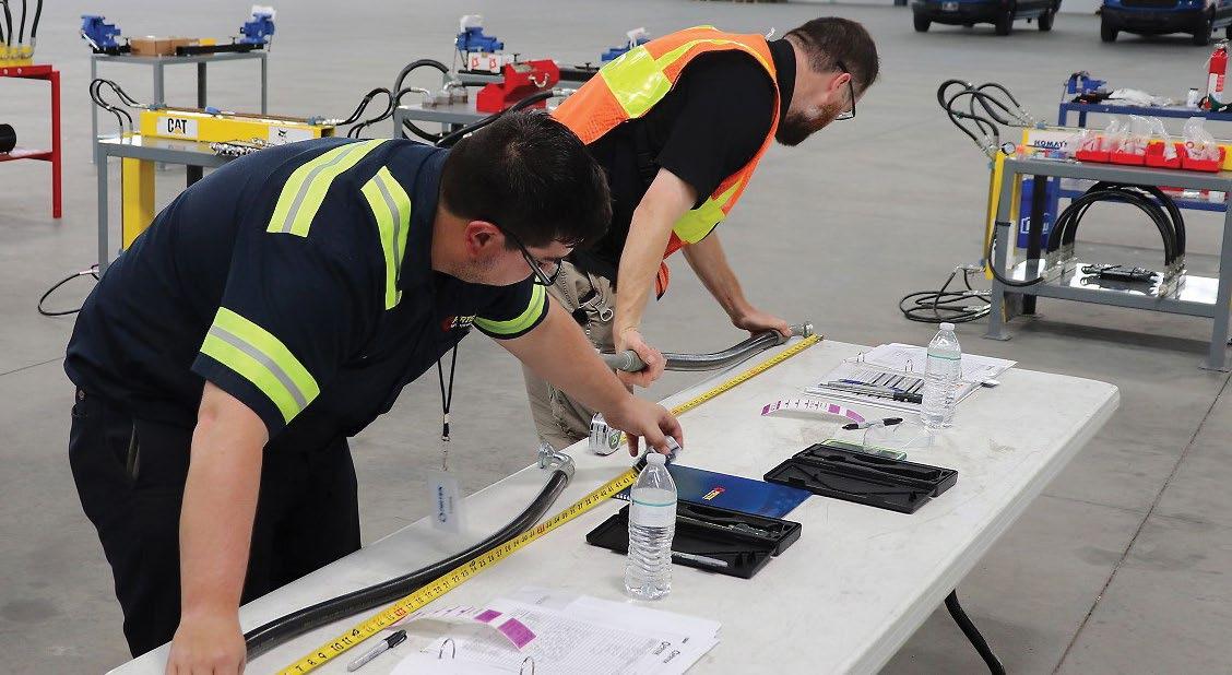
An easy way to tell if a hose needs replacement is by regular visual inspection. Look for things like oil leaks and improper hose routing. Look for loose, corroded, or damaged fittings, improperly matched compo nents, brittleness, oil permeation, or color changes to the outer cover of each hose. Look for small physical changes, like poorly crimped ends, abrasions, nicks, cuts, blisters, or cracks.
Make sure hoses are not rubbing each other or surrounding objects that can damage the hose’s outer cover. Check whether they are twisted or in a bind. A 5° twist in a hydraulic hose can reduce life expectancy 70%, while a 7° twist reduces it up to 90%.
Next, look for missing or damaged clamps, sheaves, pullies, tie wraps, guards, or other vital parts. Hoses may need to be secured to prevent rubbing and allow for proper movement of the hose throughout the machine’s normal range of motion.
Lastly, make sure the hose is protected. Place a spring guard where hoses can get smashed by falling debris, a burst sleeve if hoses are near a machine operator, a nylon sleeve to prevent rubbing and exposure to UV light, and plastic wrap to prevent hoses from rubbing on surroundings endangering people working around hose ends.
Finding any of these “red flags” on hydraulic hoses requires action. Replace any hoses that show signs of damage, misuse, abuse, premature wear, or are past their expected service life.
Check the oil
Get in the habit of checking the hydraulic oil. If it’s discolored, milky, or foamy, it may be contaminated with water, air, or other substances. Contaminated oil can cause failures throughout a hydraulic system, including premature hose failures.
Perform regular hydraulic fluid analysis. Analyzing the fluid in a pro fessional lab can prevent component failures. The hydraulic fluid is the lifeblood of the machine; ensure that it’s in good condition.
Finally, to ensure there are no leaks, test the equipment at its full oper ating pressure and normal operating temperature. Make sure no hoses are rubbing, twisting, or stretching beyond their limits throughout the machine’s normal range of motion.
Repairing hydraulic hoses is not an option. Only professionals should attempt to perform maintenance or replace hydraulic hoses to minimize health and safety risks.
Many workplace accidents, equipment failures, and hazardous envi ronmental mishaps are preventable. Investing in hose maintenance significantly saves on future replacement costs and ensures a business continues running smoothly. Acknowledging your role in running an essential business, the last thing you need is a major, preventable dis ruption caused by equipment failure. •
WWW.IFPS.ORG • WWW.FLUIDPOWERJOURNAL.COM NOVEMBER 2022 25
Pneumatic Versus Vacuum Component Design
By Dane Spivak, Engineering Manager, Davasol Inc.
» A PNEUMATIC SYSTEM is defined as an application that uses a positive pressure gas to perform an operation. A typical air compressor can generate over 100 psi greater than atmospheric pressure. Since atmospheric pressure at sea level has an expected value of 14.7 psi, pneumatic systems have available pressures of many multiples of atmospheric pressure. A vacuum system is one in which gas is removed to create a pressure lower than atmospheric pressure. Therefore, theoretically, the maximum available vacuum pressure at sea level is -14.7 psi relative to atmospheric pressure. This is a state of “perfect vacuum,” in which all gas and matter are removed from the system. It is referred to as absolute pressure.
The key takeaways from the above paragraph are that pneumatic pressures are many multiples higher than vacuum, and that pneumatic pressure is a pressure greater than atmospheric, while vacuum is less than atmospheric. These two differences play a significant role in the design and implementation of their respective components.
Before we discuss components, it is important to understand flow and pressure losses within fluid power. No system is perfectly sealed, so leakage is a relatively common occurrence. Using the appropriate components can provide near zero leakage, which is the common goal of most applications. Leaks affect pneumatics and vacuum much differently. Consider a situation in which a fitting is leaking in both a pneumatic system and a vacuum system, resulting in a pressure drop of 2 psi for each. Although 2 psi may seem fairly insignificant, a vacuum system is much more impacted. The table below shows the comparative results of these losses when vacuum has a 15% drop in pressure, compared to the pneumatic drop of 2%.
PRESSURE LOST
SYSTEM
O-rings. The fitting on the left has a standard round O-ring, while the fitting on the right has a flap shape. Under positive pneumatic pressure, tubing expands, and both seals would work well. However, under vacuum, the tubing would collapse slightly. This could result in potential leaks with the rounded O-ring, but the flap style would push out and compensate to maintain an airtight seal.
LOSS
Figure 1: Round and flap-shaped internal O-ring designs for push-to-connect fittings.

Generally speaking, all pneumatic tubing of a half-inch and under is used for vacuum as well. Arguably, harder tubing would be ideal as it seals more confidently with push fittings and collapses less to maintain maximum cross-sectional flow areas. But for the most part, these con cerns are negligible or nonexistent if the components are specified and installed correctly. A difference worth noting is a preference for clear tubing in vacuum systems to help identify any build up or blocks in the lines. This is a more frequent occurrence in vacuum due to lack of point of use or prefiltration.
Fittings larger than a half-inch often play in favor of vacuum, since a typical connection would be made by press fitting the inner diameter of a hose over top of a barbed fitting and clamped down. In this scenario, vacuum would suck the hose end down onto the fitting, resulting in a tighter fit, but pneumatic pressure would push it outward by expanding the hose.
Above all else, pneumatic systems are designed for air consumption, as most applications are frequently exhausted during cycles, such as with pneumatic actuators. Leaks, losses, and use are essentially an expecta tion and built into the system design. On the other hand, users expect vacuum systems to be nearly perfectly sealed, and the vacuum pump is sized according to this logic. Therefore, small leaks in vacuum could have a much larger impact.
For the component analysis, a good introduction is to start with the basics of fittings, tubing, and hose. Many of these parts are interchange able within pneumatics and vacuum, though there are subtle design differences that play an important role.
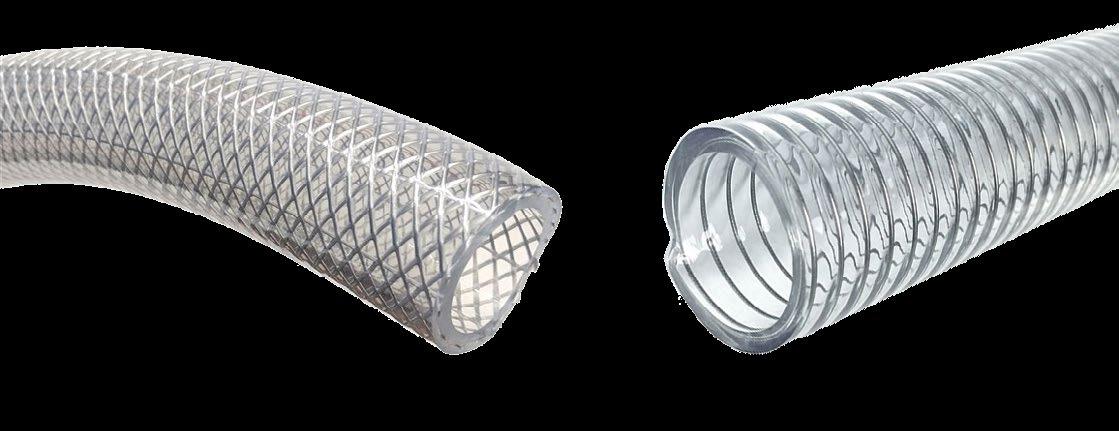
Push-to-connect fittings are the preferred connection technology for air systems for tubing a half-inch and smaller. Push-in fittings are functionally designed for pneumatic applications, though not all are suited well for vacuum. The primary reason is the internal O-ring that seals against the tubing. Figure 1 shows two fitting models with different
Unlike tubing of a half-inch and under, larger hose reacts much dif ferently under pneumatic and vacuum pressure. Because of the larger diameters, there are greater forces being applied to the hose (see figure 2). Pneumatic hoses often have mesh reinforced walls, which adds strength to combat the outward pressure inside the hose. However, the mesh design does not handle vacuum pressure well and tends to collapse the hose, restricting the flow of the system. Coiled reinforced hose is preferred for vacuum for this reason. It is ideal, as the coil shape provides the needed support of atmospheric air pushing the hose from the outside diameter due to the vacuum state within. Much like tubing, clear hose is preferred for vacuum to have a visual of the internal lines.
26 NOVEMBER 2022 WWW.FLUIDPOWERJOURNAL.COM • WWW.IFPS.ORG
ALL ABOUT VACUUM
Figure 2: Mesh pneumatic hose versus coil vacuum hose. SYSTEM
PRESSURE RESULTANT
PRESSURE
PERCENTAGE PNEUMATIC 100 psi 2 psi 98 psi 2% VACUUM 13 psi 2 psi 11 psi 15% Pressure losses of pneumatic and vacuum systems.
Filtration units and systems are common in most fluid applications. In pneumatics, compressor manufacturers often suggest very fine central ized filtration, from 1 micron to as low as 0.01 micron. The finer filtration allows for cleaner systems and exhausted air, which is a benefit for main tenance and safety. The nature of compressed air pressure allows for ease of pushing through finer filters of reasonable physical sizes and without negatively impacting the compressor or system performance.
Vacuum filtration is quite different, as a 5-micron filter element would be regarded a finer porosity. Figure 3 shows the difference between filter elements. Lower micron ratings could either restrict the flow or require a filter too large relative to the rest of the system. Given that most vacuum components and pumps can oper ate well under these filtration conditions, vacuum filter ratings are in the 5-to-40-mi cron range for a typical industrial application. However, finer and specialized filtration is applicable to certain vacuum applications.
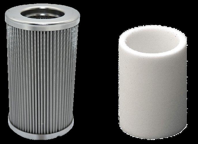
Direct-acting valves work when pure electrical energy from a solenoid controls the valve position with no other form of assistance. Direct-act ing valves can work for both pneumatics and vacuum. But depending on the valve design, vacuum may require significantly more power. Figure 5 shows a cross-sectional view of a direct-acting normally closed poppet valve. The normally closed condition means the valve is closed at its rest position and opens when powered. Under pneumatic pres sure, the valve seat pushes upward and helps the valve remain open when powered on. However, under vacuum, the pressure attempts to suck the seat back down and close the valve. For this reason, vacuum valves often require larger solenoids and more power to open valves. Some small direct-acting valves may work under both pneumatic and vacuum conditions, but the dual compatibility becomes increasingly difficult with larger sizes, since more force is applied to the valve seat. Therefore, larger direct-acting poppet vacuum valves have much larger coils than their pneumatic counterpart.
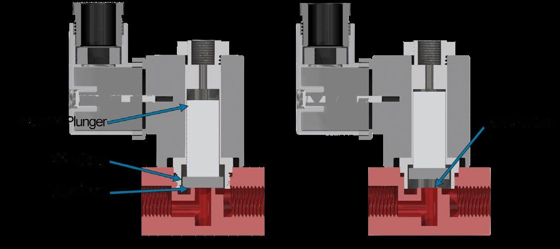
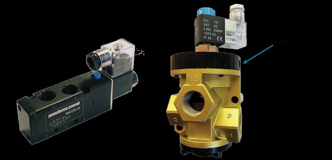
Figure 3: (Left) 40-micron and (right) 0.01-micron elements.
It is important to note that pneumatic and vacuum filters are often not interchangeable. Using the wrong filter could result in restricted flows, system leaks, or improper filtration altogether.
Control valves in pneumatics and vacuum each have their unique design features. Many pneumatic valves are internally piloted, meaning there needs to be compressed air inside the line to help the valve power and move positions. This is the typical design for the common spool valves found on pneumatic manifolds. The concept is efficient for pneumatic controls but, of course, would not work under vacuum.
Since internal pilot valves would not work under vacuum, external piloted models are a popular design choice. As the name suggests, an external pneumatic source helps power the valve and shift positions. With this design, both vacuum and pneumatic pressure in the system would be accepted since the external pneumatic source helps control the valve as a separate function. Figure 4 illustrates internal and external pilot valve models with the external pilot port indicated by the arrow.
As with many components, compared to pneumatics, vacuum requires larger flow-through areas, and that is no different when it comes to valves. Valves designed specifically for vacuum usually have much larger ori fices. Even if a valve is considered vacuum rated, the orifice size and flow capacities should be understood to ensure it works well with the system as a whole. The same would apply to pneumatics, of course. Additionally, the manufacturer should confirm that the valve models are specified for pneumatic and vacuum pressures. Although theoretically a valve should work, the internal designs may experience leaks or damage.
This article touched on many design considerations for pneumatic and vacuum components, including fittings, tubing, hose, filtration, and valves. It was intended as a conceptual analysis only. Automation manufacturers and design defaults often favor pneumatics, so it is imper ative to understand the functionality and specifications of each part in a vacuum system. Every application is unique and professional assistance is always recommended.
This article is the opinion of the author, Dane Spivak of Davasol Inc., an industrial brand management firm. One of Davasol’s clients, Vacuforce LLC, based in Indianapolis, partnered with the author on this article. Contact Dane Spivak at dspivak@davasol.com.
WWW.IFPS.ORG • WWW.FLUIDPOWERJOURNAL.COM NOVEMBER 2022 27
Figure 4: (Left) internal and (right) external pilot valves.
Figure 5: Cross-sectional direct-acting poppet valve.
Without Skilled Tradespeople, Who Builds It?
 By Gordon Kolasingh, Chief Operating Officer, Orange Seal
Imagine for a moment you’re an architect or an engineer meticulously drafting your grand design. You have an insatiable desire to see your plan become something tangible, but you’re stymied; there are simply no individuals with the skills to build it. No welders, carpenters, plumbers, electricians, masons, or specialists of any kind. There are no tradespeo ple, so now what?
Although this isn’t yet a reality, it’s not far removed from the difficulty we face finding individuals with these skills. The problem isn’t exclusive to architects and engineers either. Finding qualified plumbers or electricians to help with problems in your home can be time consuming and expensive.
The worker shortage has impacted fluid power companies too. Industry leaders have long talked about the challenges of finding and retaining employees to do all the work that swamps many of them.
For years our culture has encouraged young people to pursue costly college-level education as the only pathway to success. Meanwhile, trade skills continue to be stigmatized. It’s an easy dichotomy to understand. After all, why choose a career steeped in manual labor when a temperature controlled, high-rise corner office overlooking the city is possible? There are merits to this way of thinking, but many of the arguments against skilled trades quickly fall apart. Wages are comparable if not better in the trades, career pathways are plentiful and varied, and technology in the trades is rapidly advancing and not nearly as antiquated as some might believe. Becoming certified in a trade incurs little financial debt. Many of those working in the trades report that their jobs are highly fulfilling.
28 NOVEMBER 2022 WWW.FLUIDPOWERJOURNAL.COM • WWW.IFPS.ORG
A study conducted by Stanley Black & Decker in August and September 2021 among 801 high school sophomores, juniors, and seniors found that 85% of them saw trades as a good career choice, but only 16% were very likely to consider it themselves. According to the study, a major inhibiting factor was a lack of awareness about trade skills, including how they provide financial stability and overall job satisfaction. It isn’t entirely surprising that college educations and white-collar careers are lauded as superior to the trades while vocational careers are labeled as “dirty work.” These attitudes persuade young people that the trades require laborious, backbreaking work and aren’t nearly as lucrative as careers requiring a degree, when the truth of the matter is that trade careers provide a high quality of life and job satisfaction.
The outlook
The push toward college and away from trade skills has led to a wid ening chasm between the available jobs requiring these skills and the number of individuals capable of filling them. This is a serious problem. Skilled trades are a major contributor to the backbone of society, and if this problem isn’t addressed, the ramifications will be far reaching and detrimental. For example, in the U.S. in 2022, an estimated 650,000 jobs remained open in the construction industry, according to Stanley Black & Decker’s CEO Jim Loree.
We’re already seeing the impact of the growing skills gap. As the current workforce ages, measures may be needed to ensure the continuance of some fundamental services.
Technology has helped compensate. Contrary to the belief that manufac turing operations are antiquated, manufacturing has been at the forefront of integrating sophisticated technological components. Running these systems efficiently requires skilled technicians and operators whose knowledge and abilities are more and more specialized.
The challenge remains to treat the underlying cause of the trade skills gap: young people's lack of interest in vocational education. Numerous efforts are underway to encourage interest in the skilled trades. That was the progenitor for a response to the crisis by my company, Orange Seal, which launched Project Dragonfly, an online platform built to re-educate younger people about the positives of learning trade skills. The Project Dragonfly platform presents an easy pathway to learning these skills and features a growing online database of nationwide training programs. The project aims to shift the percep tion of trade skills, encouraging young people to embrace them as a career pathway.
Many large entities with the necessary clout and capital for large-scale training and outreach programs still sometimes fail to connect with the audiences they’re trying to reach. Younger generations tend to view their futures holisti cally, tying together financial stability and overall sense of fulfillment, with the latter often holding greater importance. They need, therefore, to be approached in ways that demonstrably define pathways highlighting both ambitions. They need to be shown that college debt isn’t necessary to being a high earner, nor is it a requirement to advancement and a high level of satisfaction.
Fluid power’s two major bodies – the National Fluid Power Association and the International Fluid Power Society – have put forward their own efforts to lure young people into careers in fluid power. IFPS offers pathways to certification in fluid power by providing materials and testing. IFPS also offers courses, workshops, and seminars in fluid power. NFPA manages its Education and Technology Foundation to meet the needs of the future’s fluid power workforce.
These organizations have made gargantuan efforts in their own niches. More and more, we need to provide a space for their members and encour age the development of students who may one day be members themselves.
Flip side of the coin
Many employers hold values and operate in ways that are in tension with younger generations. There is no denying that some employers instituted practices and working environments that left their workers disgruntled and bitter. Some things that arise tend to gain a lot of attention. We’ve seen this with the recent fervor for unionization. It’s no surprise that it is happening because of the disconnect between those with skills and the organizations that need them.
We need to devote our efforts to removing the stigma surrounding the trade skills. We should not hide the reality that some trades require significant effort. But if we demonstrate the substantial payoffs, perhaps we’ll see the renewed interest that is so desperately needed. We must show younger generations how trade skills are the hallmark of true crafts people. They need exposure to the advantages of the skills in ways with which they can connect on a personal level.
Trade skills and working with one’s hands were once considered the realm of the artisan. With trends and nature being as cyclical as they are, perhaps it’s time for that cycle to begin again. •
efficient reliable tight
Plugs with integrated molded NBR or FKM seal. Automatically assembled with integrated control. Our products can be found worldwide in hydraulic applications and drive technology. We stock for you.

It’s our turn.
mail@heinrichs-usa.com | +1 859 371-4999
HN 10-WD | SCREW PLUG Our solution


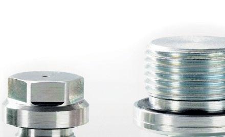

heinrichs-usa.com


WWW.IFPS.ORG • WWW.FLUIDPOWERJOURNAL.COM NOVEMBER 2022 29
CONTROL
Stop the

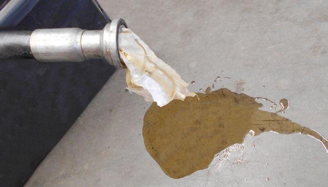
THE FLANGELOCK™ TOOL AND CIRCUIT BLANKING CAPS
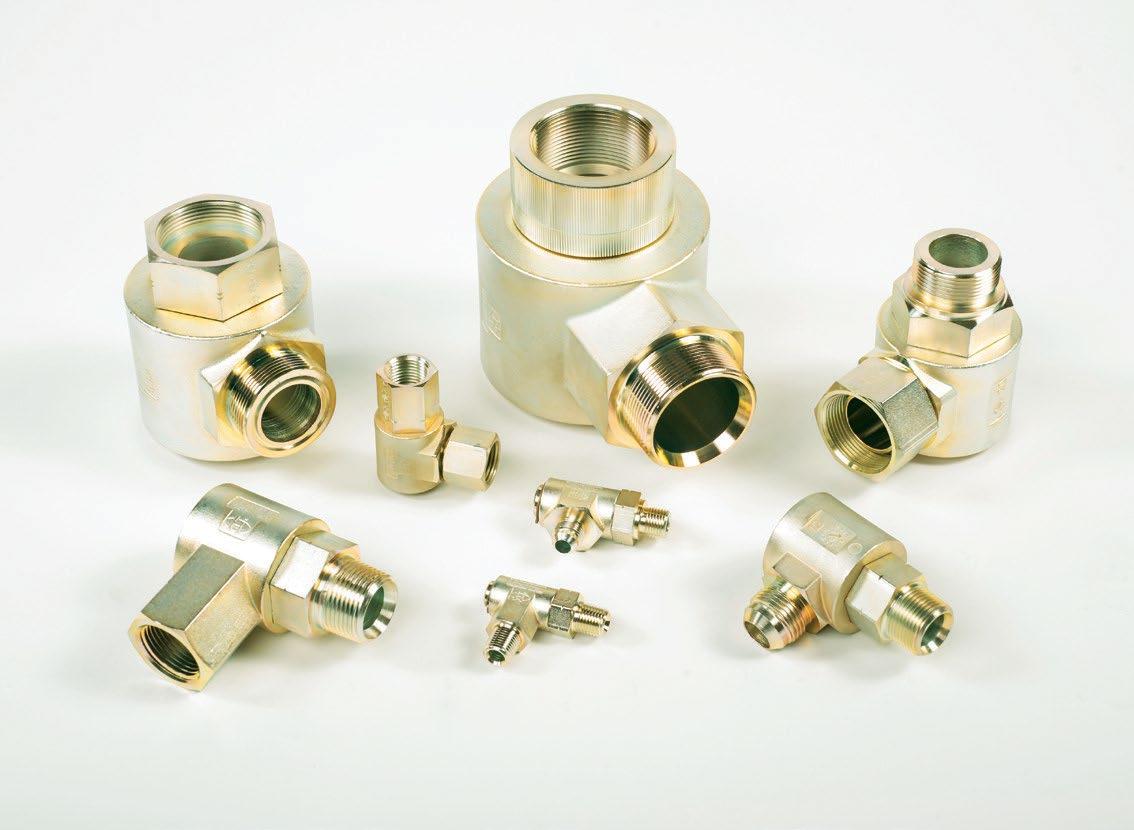
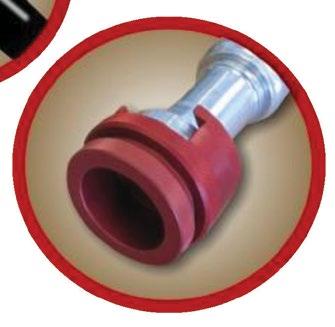
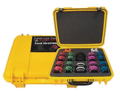

CONTAMINATION

30 NOVEMBER 2022 WWW.FLUIDPOWERJOURNAL.COM • WWW.IFPS.ORG The FlangeLock™ Tool is the ultimate contamination control tool for protecting your hydraulic systems. It allows for the simple sealing of open SAE code 61, 62 & CAT-Style hydraulic flanges without tools. Constructed from lightweight aluminum. Easy on, easy off. Offers a leakproof solution to hydraulic system and environmental cleanliness. FlangeLock™ Tools stop the mess!
Mess SAVE TIME SAVE MONEY SAVE LABOR SAVE OIL For more information, call (203) 861-9400 or email sales@flangelock.com. www.flangelock.com • No tools required • No expensive hardware needed • No more rags stuffed into hoses • No more messy plastic caps • The ultimate contamination control tool • One hand installation • Eliminate hydraulic oil spills & clean up • Quick installation & ease of usage • Safe for personnel & environment • Industry acclaimed This product is Patented, other Patents pending. CONTAMINATION
Routine and scheduled maintenance of hydraulic systems are vital to getting the most out of your Hitachi Mining Excavator. While maintenance plays the largest role in the prevention of unnecessary machine downtime, it can also expose the hydraulic system to high levels of contamination rapidly decreasing component longevity. The importance of contamination control is sometimes overlooked when performing maintenance due to incorrect practices being used.
The FlangeLock tool and caps are the ultimate contamination control tools for protecting your hydraulic system. The FlangeLock allows for the simple sealing of open hydraulic flanges without tools while the caps can be bolted in place of a flange connection. Easy on, easy off, they offer a leak-proof solution to hydraulic systems and environmental cleanliness. FlangeLock™ tools and caps stop the mess. HITACHI MAKING
CONTROL EASY Hitachi have packaged FlangeLock™ tool and caps specifically for Hitachi mining excavators. The Hitachi customised kits make sure no matter which component routine maintenance is being performed on, you will always have the exact number of FlangeLocks * and caps to help reduce contamination. *Note: FlangeLocks™ are not to be used under pressure Call you local Hitachi Muswellbrook representative or the branch on 02 6541 6300 for more information. The “9S” Series swivels represent one of the most complete range of sizes and configurations available to the industry. This series has been redesigned to incorporate a one piece barrel arrangement thus eliminating the need for braze joints. These swivels are pressure balanced with operating pressures up to 5,000 psi. All configurations are designed with a 4:1 Safety Factor and include RoHS compliant zinc plating. P.O. Box 6479, Fort Worth, TX 76115 V. 817/923-1965 www.hydraulicsinc.com 9S SERIES INVESTMENT CAST SWIVELS Introducing!
FLOW
STOCK
25MM
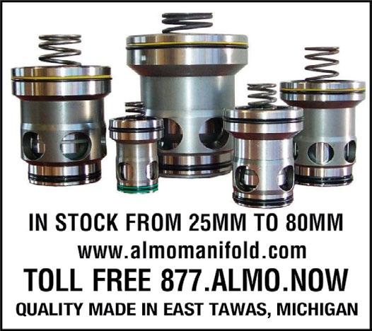
HYDRAULIC
and COMPONENTS

“SPECIAL” YOU WANT IS PROBABLY ON OUR SHELVES
MAIN Mfg. Products, Inc.


www.FluidyneFP.com
www.Gemels.com
www.Heinrichs-USA.com
www.jtHydraulics.com
www.LaMan.com
www.Lubriplate.com


www.MackCorp.com

www.MainMFG.com
www.MOCAP.com
www.Norgren.com

www.PeninsularCylinders.com
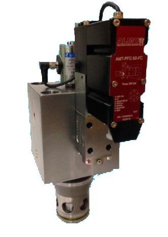
www.Tele-Radio.com/us/
www.TexcelRubber.com
www.Vac-Cube.com

www.WCBranham.com
www.YatesInd.com
WWW.IFPS.ORG • WWW.FLUIDPOWERJOURNAL.COM NOVEMBER 2022 31
FLANGES
THE
800.521.7918 fax 810.953.1385 www.MAINMFG.com/fpj HIGH
PROPORTIONAL FLOW CONTROL • 16MM to 50mm • Standard ISO 7368 and DIN 24342 cavity • High performance 5,000 psi • On board amplifier • 0-10 volt command almomanifold.com Phone: 989.984.0800 Toll Free: 1.877.ALMO. NOW Fax: 989.984.0830 IN
FROM
TO 80MM MANY COVERS IN STOCK • Pressure, Flow, Directional • Large Flow 90° Valves almomanifold.com Phone: 989.984.0800 Toll Free: 1.877.ALMO. NOW Fax: 989.984.0830 • Single DIN blocks • Active Valves • Monitored Poppets The correct answers to Test Your Skills on page 11 are 1-c and 2-a. CLASSIFIEDS ADVERTISER INDEX Compact, quick, powerful! Large Inventory Standard, High Flow, Latching & ISO Series 10 & 15 mm Electronic Valves 877-245-6247 Technical Support Company .................................................................. Page ........................................................ Phone ............................................................................... Web AEM Inside Front Cover www.IFPE.com Almo Manifold 31 1-989-984-0800, 1-800-ALMO-NOW www.AlmoManifold.com CFC-Solar ..................................................................... 13 ............................................ 513-874-3225 ....................... www.CFCINDUSTRIALTRAINING.com Clippard .................................................................. 23, 31 .........................................1-877-245-6247 ....................................................... www.Clippard.com Flange Lock 22, 30 203-861-9400 www.FlangeLock.com Fluidyne Fluid Power 31 1-586-296-7200
Gemels spa 9, 21
Heinrichs ...................................................................... 29 ............................................ 859-371-4999 ............................................
Hydraulics, Inc. 20, 30 817-923-1965 www.HydraulicsInc.com J/T Hydraulics & Service Co. 20 1-800-591-8280
La-Man Corp. 14, 22 800-348-2468
Lubriplate 3 800-733-4755
Mack Automation 23 928-526-1120
Main Manufacturing Products 21, 22, 31 1-800-521-7918
MOCAP INC 20 1-800-633-6775
Norgren Outside Back Cover 1-800-514-0129
Peninsular Cylinder Co. Inc 11 1-800-526-7968
Tele Radio LLC 9 866-629-0780
TEXCEL 22, Inside Back Cover 800-231-7116
Vac Cubes 30, 20 727-944-3337
W.C. Branham Inc. 21 715-426-2000
Yates, Inc. 1, 21 1-586-778-7860
01 YES! Please start/continue my complimentary subscription to the Fluid Power Journal 02 NO. Not interested. Signature (required) Title (required) Date (required) / / Telephone Fax E-mail Please Type or Print Clearly: First Name Middle Initial Last Name Company Division Web Address Address Mail Stop City State Zip Code Check here if you would like to keep your name, address, phone and fax numbers confidential, and not released to third parties The address above is my: Home Address Business Address Which edition would you like to receive? Print Digital Both (View a sample of our PAPERLESS digital edition at www.fluidpowerjournal.com) SUBSCRIBE BY MAIL 1. Do you specify, select or influence the purchase of components & systems, on new or existing machinery? 03 Yes 04 No. If yes, which technologies? (check all that apply) 05 Hydraulic 06 Pneumatic 07 Vacuum 08 Electronic Controls 09 None of These 2. What is your primary job title? (check only one) 10 Administration: Chairman, President, V.P., Secretary, Treasury, General Manager, Owner, Business Manager, Director, etc. 11 Plant Operations: VP of Manufacturing/ Operation/ Production, Plant Management/ Director/ Manager/ Supervisor/ Superintendent/ Foreman/ Safety Director, etc. 12 Engineering: V.P. Eng., Eng., Design Eng., Director of Eng., Staff Specialist, Chief Eng., Senior Eng., Maintenance/Production Eng., etc. 13 Technical: Chief Tech., Fluid Power Tech., etc. 14 Mechanical: Chief Master Mech., Master Mech., Fluid Power Mech., etc. 15 Purchasing: VP/Director of Purch., Procurement Manager, Buyer, Purch., etc. 16 Other: (please specify)_________________________________________________________________________________________________ 3. Number of employees at this location? A 1-19 B 20-49 C 50-99 D 100-249 E 250-499 F 500-999 G 1000+ 4. What is the primary business activity at this location? In the Fluid Power Industry, Outside the Fluid Power Industry 56 Manufacturer 57 Distributor 58 Education 59 Original Equipment Manufacturer (OEM) 60 End User of Fluid Power Products 61 Other: (please specify)__________________________________________ 5. Which of the following best describes your market focus? A Aerospace A Marine & Offshore Equipment B Agricultural Machinery B Material Handling Equipment C Automotive C Mining Machinery D Civil Engineering D Packaging Machinery E Cranes E Plastic Machinery F Drills & Drilling Equip. F Presses & Foundry G Flame Cutting/Welding Equip. G Railroad Machinery H Food Machinery H Road Construct/Maint. Equip. I Forestry I Simulators & Test Equipment J Furnaces J Snow Vehicles, Ski Lifts K Gas & Oilfield Machinery K Steel Plants & Rolling Mills L Heavy Construction & Equip. L Truck & Bus Industry M Military Vehicles M Textile Machinery N Construction & Utility Equip. N Woodworking Machines O Machine Tools O Other (specify)_____________ P Government Related P Fluid Power Industry FILL OUT THIS CARD COMPLETELY, DETACH, AND MAIL OR FAX IT TO START YOUR SUBSCRIPTION MAIL TO: PO BOX 2548 • ORLANDO, FL 32802-9830 • FAX: 1-866-207-1450 YOU CAN ALSO SUBSCRIBE ONLINE AT WWW.FLUIDPOWERJOURNAL.COM. MY COMPANY SHOULD BE ADVERTISING IN OR SUBMIT AN ARTICLE TO THE FLUID POWER JOURNAL. PLEASE CONTACT THIS PERSON: NAME: TITLE: PHONE: SCAN HERE
One Fluid Solution For Your Hydraulic Needs.
We offer high-quality hydraulic hoses, fittings, and accessories with unmatched customer service to keep your business Ahead Of The Curve.
Your Partner For Over 40 Years
Rely on Texcel’s experienced and knowledgeable team for sales, technical support, customer service, and more.

Extensive & Premium Product Range
Our broad range of high-performing hydraulic hoses and fittings are designed to exceed your toughest applications.

Swift Service & Exceptional Inventory

Explore our U.S. hydraulic inventory, and buy everything you need on one Purchase Order with a 99.9% error-free rating.
Streamline Your Productivity With Premium Hydraulic Products & Services.

TexcelHydraulics.com | 800.231.7116 | sales@TexcelRubber.com
Testing | Certification | Secure Online Portal | Technical Support | 24-Hour Response Team
SCAN TO GET STARTED
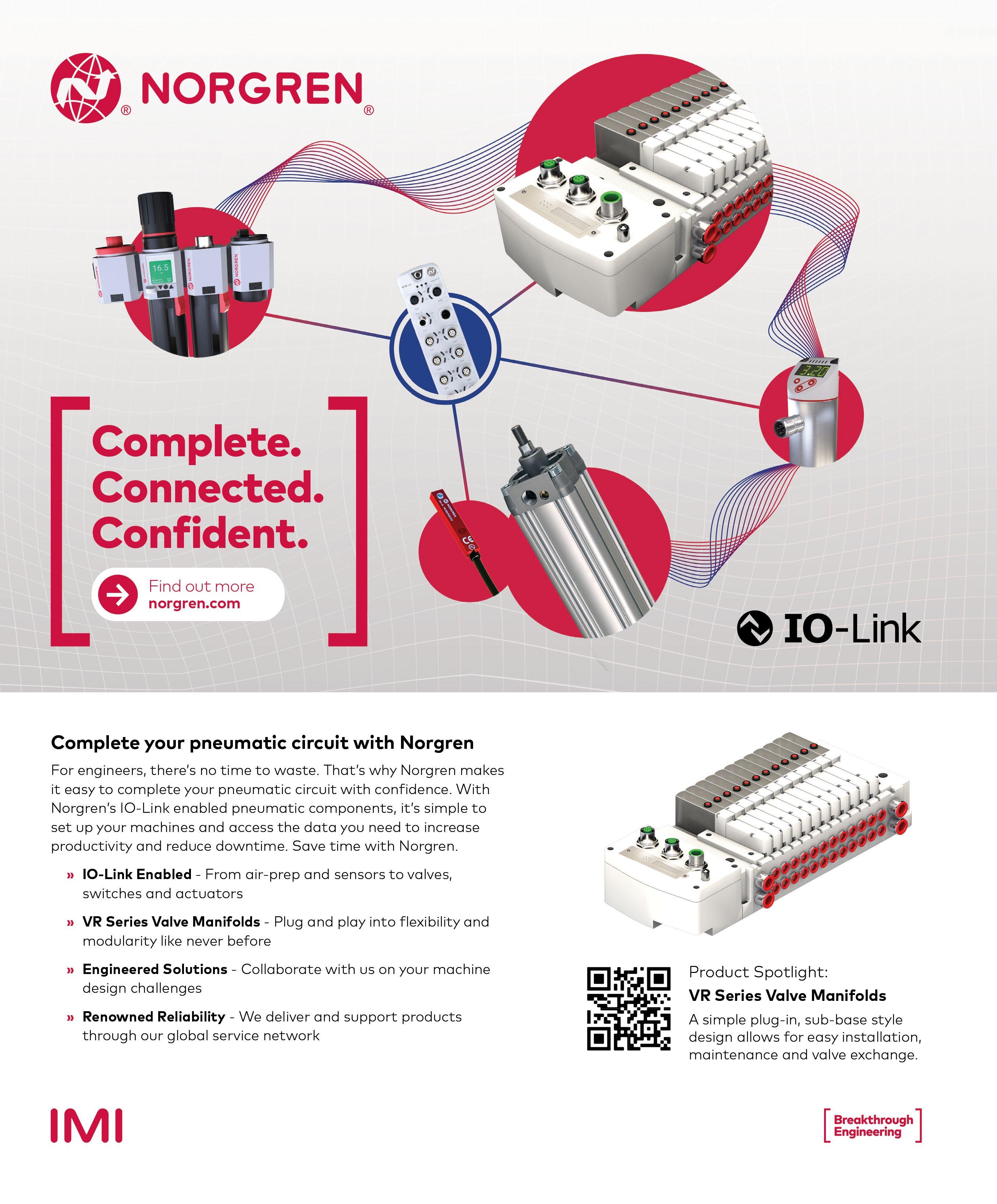


 By Gordon Kolasingh, Chief Operating Officer, Orange Seal


