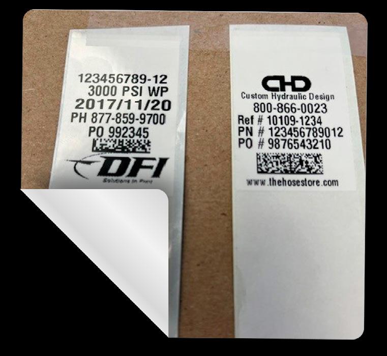
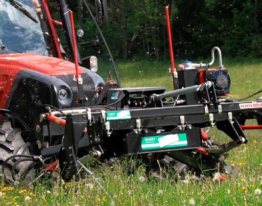
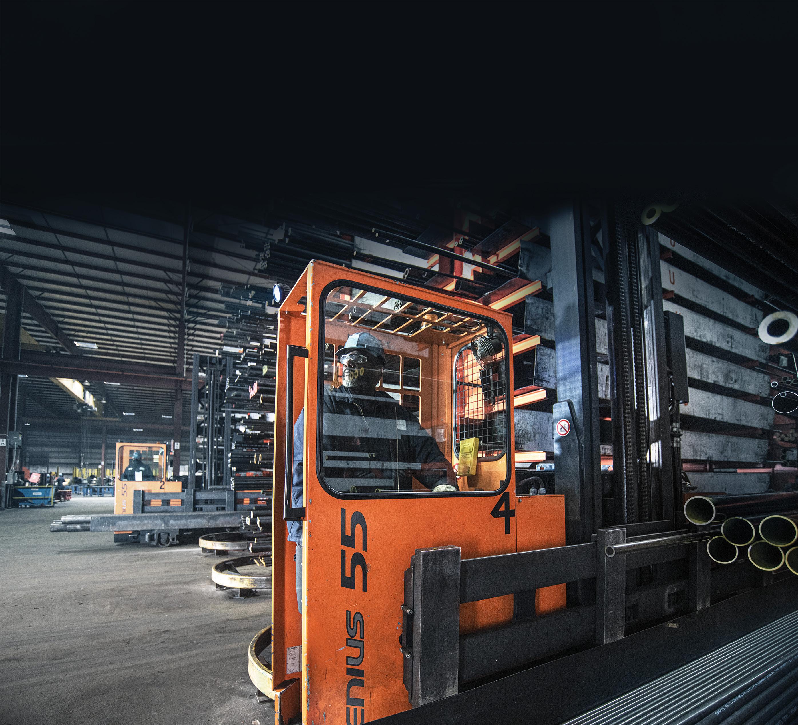
Hoses Labeling hydraulic hoses with 2D barcodes or QR codes ensures quick replacements, minimizing costly equipment downtime.
Controlling
Maintaining
Publisher’s Note: The information provided in this publication is for informational purposes only. While all efforts have been taken to ensure the technical accuracy of the material enclosed, Fluid Power Journal is not responsible for the availability, accuracy, currency, or reliability of any information, statement, opinion, or advice contained in a third party’s material. Fluid Power Journal will not be liable for any loss or damage caused by reliance on information obtained in this publication.
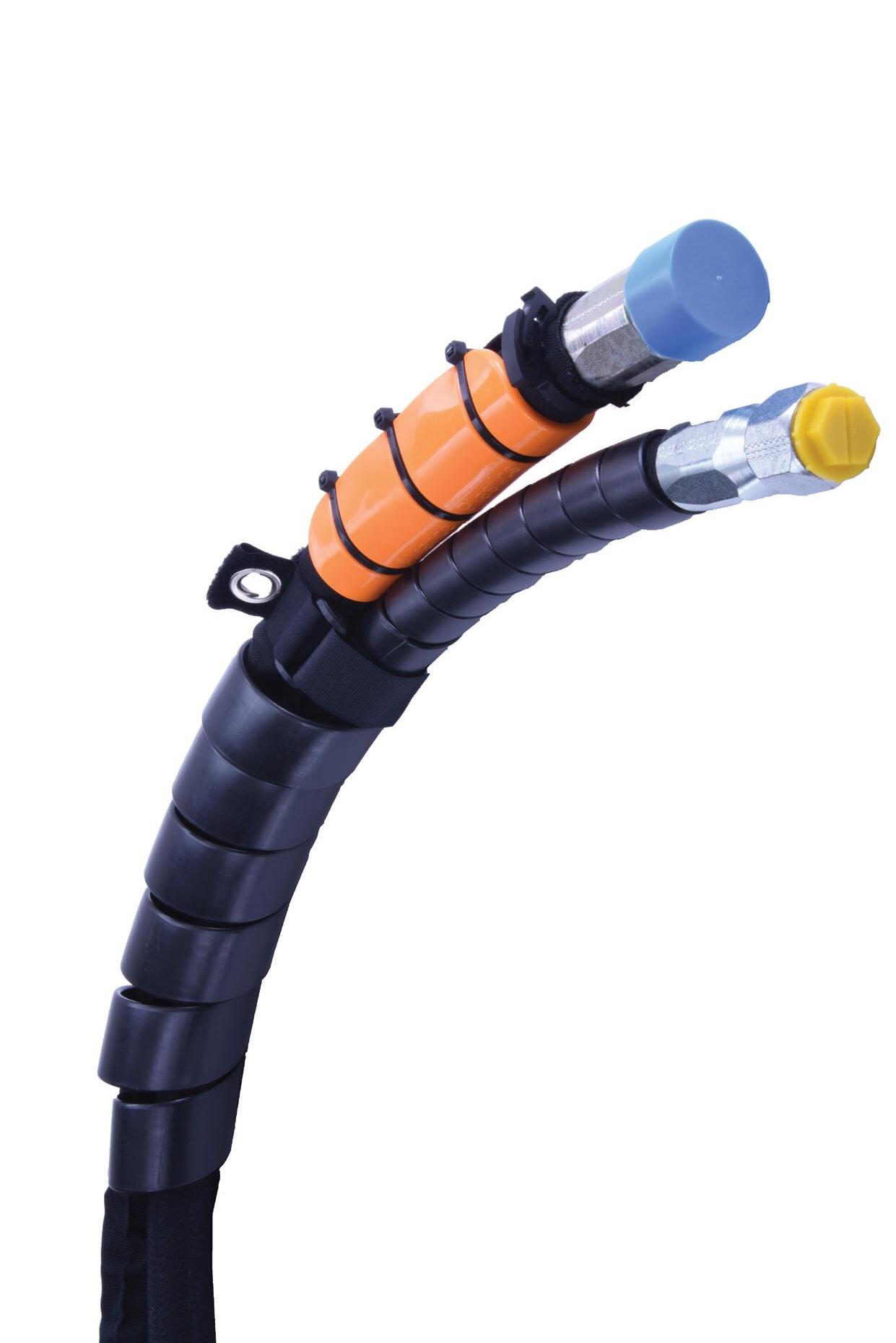
Avoid costly downtime from ruptures, contamination, and damaged ttings by protecting your entire hydraulic hose assembly with Essentra’s complete line of protection products.
- Spiralguard
- Tectorguard
- Point of Contact Protector
- Hose Sleeves
- Hydraulic Caps & Plugs
- Hose Bundling and Securing Clamps & Straps
Empowering Industry Excellence
THE TRANSFORMATIVE IMPACT OF IFPS CERTIFICATIONS IN FLUID POWER EDUCATION AND BEYOND
By Brian Wheeler, CFPAI, CFMIP, CFMM, CFAJPP, IFPS Board of Directors VP- membership, Boeing Production System Training
» SINCE 2016, I have had the privilege of teaching Fluid Power courses at the Boeing Company to mechanics and technicians. This opportunity has not only allowed me to share my passion for the subject but has also played a significant role in the growth of our industry. However, my responsibility as an instructor extends beyond the classroom. I have also dedicated my time to helping high school students understand the intricacies of Fluid Power by assisting on a First Robotics league team. The impact of IFPS Certifications which started for me in 2013 when I was still a shop floor mechanic taking care of CNC machines.
I wanted to help drive safety, standardization, and quality within my company as so many lacked understanding and were just component swappers hoping that it would fix the problems with the machines.
IFPS Certifications are crucial in ensuring that professionals in the fluid power industry adhere to the highest standards of safety, quality, and performance. By obtaining these certifications, individuals demonstrate their expertise, proficiency, and commitment to upholding industry best practices. As an instructor, I emphasize the importance of IFPS Certifications to my students, highlighting how certification not only validates their knowledge and skills but also elevates the standards of the entire industry.
Having experienced the transformative power of IFPS Certifications in my own career, I understand firsthand the significance of these certifications in advancing one's professional growth and opportunities. Achieving IFPS Certifications is a testament to dedication, hard work, and a deep understanding of fluid power principles. It opens doors to new career prospects, enhances credibility, and positions individuals as valuable assets in their fields.
The pride that comes with seeing my students successfully earn their IFPS Certifications is unparalleled. It signifies not only their academic achievement but also their readiness to contribute to the industry. Witnessing their growth from students grappling with complex theories to certified
professionals ready to make a tangible impact in the field, is a rewarding journey that reinforces the importance of continuous learning and development.
Moreover, IFPS Certifications serve as a driving force for industry-wide improvement, setting benchmarks for excellence and promoting a culture of continuous improvement. Professionals who hold IFPS Certifications are equipped with the knowledge and skills to uphold the highest standards, contributing to a safer and more efficient field in which they work in.
As an educator, I take pride in guiding my students towards IFPS Certifications, knowing that the knowledge and competencies they acquire will not only benefit them individually but also contribute to the overall advancement of the industry. Seeing my students excel in their certification exams and emerge as certified professionals is a testament to the transformative power of education and certification in shaping successful careers.
In conclusion, teaching Fluid Power courses at the Boeing Company and witnessing my students achieve IFPS Certifications is a journey of pride, growth, and industry advancement. The combination of theoretical knowledge, practical skills, and certification attainment not only propels individuals towards success but also elevates the fluid power field as a whole. As an educator, I am committed to nurturing the next generation of certified professionals who will drive innovation, safety, and quality in the fluid power industry.
Technical Editor: Dan Helgerson, CFPAI/AJPP, CFPS, CFPECS, CFPSD, CFPMT, CFPCC
Senior Marketing Consultant: Bob McKinney
Graphic Designer: Nicholas Reeder
Accounting: Kim Kressman, Donna Bachman
Circulation Manager: Josh Shoup
INTERNATIONAL FLUID POWER SOCIETY
1930 East Marlton Pike, Suite A-2, Cherry Hill, NJ 08003-2141
Tel: 856-424-8998 • Fax: 856-424-9248
Email: AskUs@ifps.org • Web: www.ifps.org
2024 BOARD OF DIRECTORS
President: Jeff Hodges, CFPAI/AJPP, CFPMHM - Altec Industries, Inc.
Immediate Past President: Scott Sardina, PE, CFPAI, CFPHS - Waterclock Engineering Corporation
First Vice President: Garrett Hoisington, CFPAI/AJPPOpen Loop Energy
Treasurer: Lisa DeBenedetto, CFPS - GS Global Resources
Vice President Certification: James O’Halek, CFPAI/AJPP - The Boeing Company
Vice President Marketing: Chauntelle Baughman, CFPHSOneHydraulics, Inc.
Vice President Education: Daniel Fernandes, CFPAI – Hawe Hydraulik
Vice President Membership: Brian Wheeler, CFPAI/AJPP - The Boeing Company
DIRECTORS-AT-LARGE
Bradlee Dittmer, CFPPS - IMI Precision Engineering Brian Kenoyer, CFPHS - CemenTech Bruce Bowe, CFPAI/AJPP - Altec Industries, Inc.
Cary Boozer, PE, CFPE - Motion Industries, Inc.
Ethan Stuart, CFPS, CFPECS - Quadrogen Power Systems
Jon Rhodes, CFPAI, CFPS, CFPECS - CFC Industrial Training
Stephen Blazer, CFPE, CFPS - Altec Industries, Inc.
Wade Lowe, CFPS - Hydraquip Distribution, Inc.
Jeff Curlee, CFPE, Cross Mobile Systems Integration Deepak Kadamanahalli, CFPS - CNH Industrial Steven Downey, CFPAI/AJPP - Hydraulex John Juhasz, CFPS - Kraft Fluid Systems
Fluid Power Journal (ISSN# 1073-7898) is the official publication of the International Fluid Power Society published monthly with four supplemental issues, including a Systems Integrator Directory, Off-Highway Suppliers Directory, Tech Directory, and Manufacturers Directory, by Innovative Designs & Publishing, Inc., 3245 Freemansburg Avenue, Palmer, PA 18045-7118. All Rights Reserved. Reproduction in whole or in part of any material in this publication is acceptable with credit. Publishers assume no liability for any information published. We reserve the right to accept or reject all advertising material and will not guarantee the return or safety of unsolicited art, photographs, or manuscripts.
NEW PROBLEM
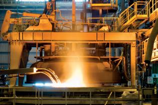
A Rolling Steel Mill Had Trouble With the Roll Removal Circuit Trying To Eject a Roll
»THE CIRCUIT ATTACHED shows the hydraulic system used for roll removal at the end of the line. They could remove small rolls with no problems, but the larger rolls would move very slowly or not at all. This required the operator to use an overhead crane that slowed down the production cycle time.
The main system pressure was set at 13.8 MPa (2,000 psi) and the pressure reducing valve output was still reading 3.9 MPa (572 psi).
Any idea what could be causing the problem?
For the solution, see page 25.
Robert Sheaf has more than 45 years troubleshooting, training, and consulting in the fluid power field. Email rjsheaf@cfc-solar.com or visit his website at www.cfcindustrialtraining.com. Visit fluidpowerjournal.com/figure-it-out to view previous problems.
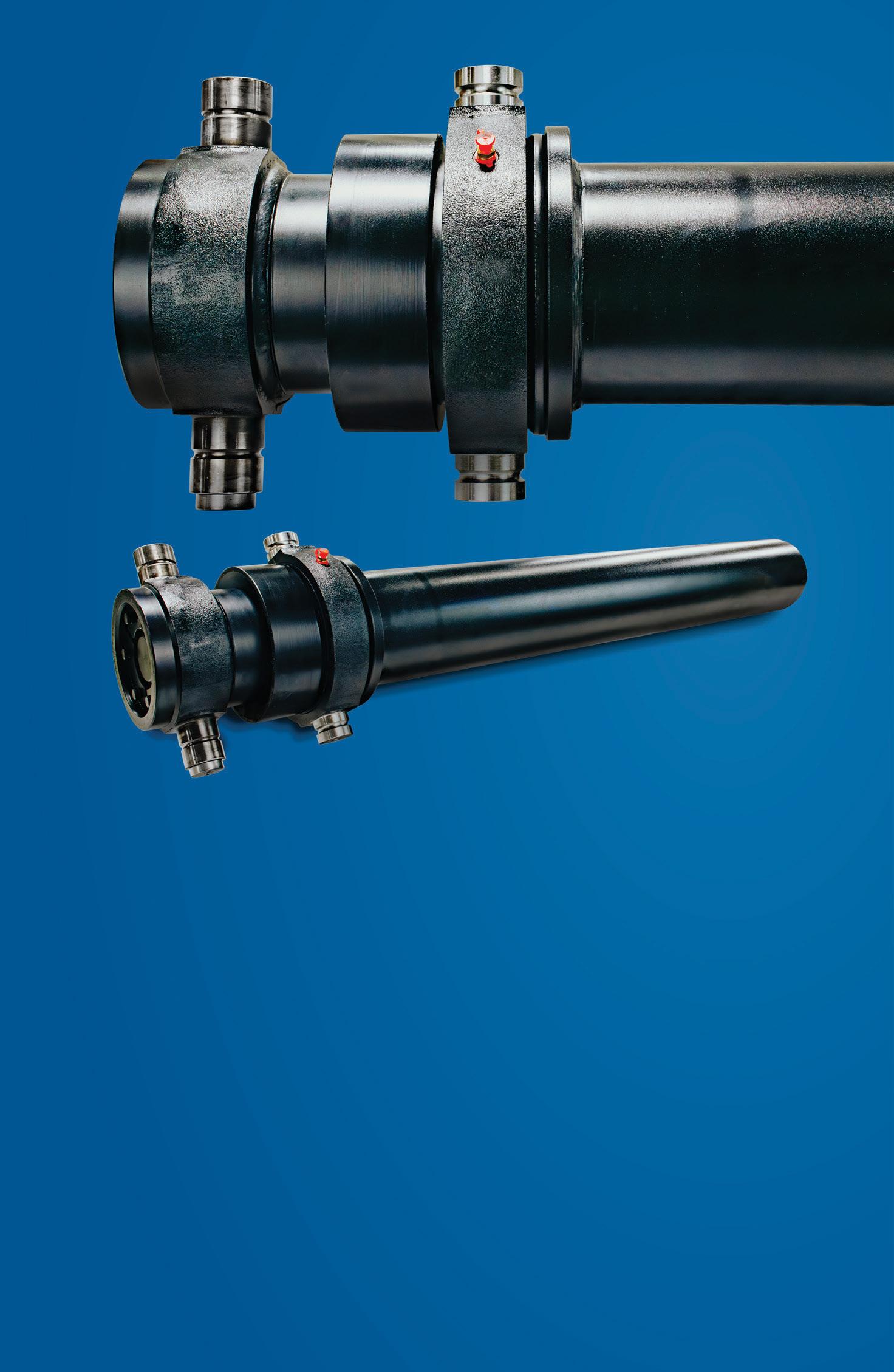
Swivel - Rotary Union
NASA Crawler Cylinders
Custom Cylinders
Spherical Bearings and Rod Eyes
Rotary Actuators
Seals
By Jeff L. Bassindale, VP of Sales-Partner, DFI Solutions
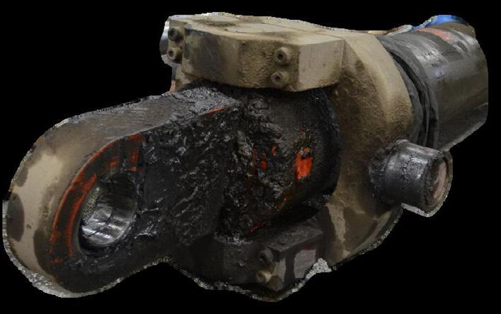
Labeling hydraulic hoses has become essential in the Hydraulic Hose & heavy equipment industry today. Imagine owning or renting heavy equipment where the hourly cost maybe upwards of $1,600 per hour, then the hose blows or fails. It is imperative that the hose gets replaced asap. How that specific hose is labeled or tagged will have a huge impact on how fast it can get replaced.
Several years ago, many hoses were tagged with a metal band with part number stamped in it, this number had to be called in or the hose had to be brought in to the dealer or shop for a replacement so they could match the hose needed.
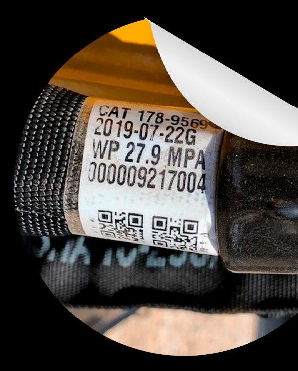
Today this can be accomplished by scanning a 2D barcode or QR code printed on a label which takes the person scanning or
needing the hose to the dealer's website with the correct part number.
Because the part number is clearly labeled on the hose, the part number can be called in or emailed to the dealer. In most cases, by the time the user gets to the dealer the hose has been made and they can head back to the work site.
The overall cost of the equipment that is shut down by failure of a hose can cost the operator or his company thousands of dollars if the equipment remains down, not to mention rescheduling the job and other contractors affected by the delay.
Many refer to this type of label as a Smart Label because it contains much key information. Users print a label containing a QR code or a 2-D barcode on the label (which can contain a paragraph of information). In most cases, the dealer that is renting the equipment can embed their website and part number of that particular hose in the 2-D barcode. The QR code while very popular, as most people recognize it in the marketplace, it isn’t recommended for curved
surfaces and can cause issues reading in the field. The QR code can be read by smart phones, unless the curvature of the hose prohibits a clear read. A better choice is a 2-D barcode such as a datamatrix rectangular barcode. This bar code symbology is proven in the field.
There are many solutions on the market today offering this label solution, allowing the user to print their own hose labels with all of the pertinent information needed. When the correct material is used, it provides these main benefits:
▶ Self-laminated label with protection from all solvents
in Print
▶ Chemical, oil, brake cleaner and water resistant
▶ UV resistant, it won’t fade in the sun
▶ Durable material with aggressive adhesive
▶ Made to last 5-7 years outdoors in most environments
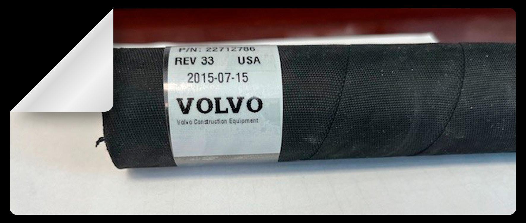
Typically the label will contain the following information:
▶ Dealer Name or contact info (maybe embedded in a 2D bar code)
▶ Logo
▶ Part number or hose description
▶ Date
▶ Customer name
▶ Hose description
▶ Other static or variable information
Many of these solutions can be standalone without connecting to a host system. However there are options to print from a network as well.
TYPICAL SOLUTION
To print variable information on a durable material typically you will use a Thermal Transfer Printing process which uses a printer such as a Zebra, TSC, Honeywell or SATO thermal transfer printer. These printers use heat to transfer ink from a specialized ribbon to a durable outdoor material with aggressive durable adhesive.
The total solution can be relatively inexpensive with a standalone printer ranging in cost from $600 to $2000, depending on type of printer and the volume of labels need to be printed daily.
These printers are the workhorse of manufacturing & industrial bar code labeling applications worldwide.
LASER PRINTERS
Those who already have a laser printer may see them as an inexpensive option but there are some obstacles. The material to be printed must be available in sheets that can be used by the printer. This limits the type and quality of the available material.
It’s doable but requires special converting of durable material which many times typically aren’t converted into sheets, which is what the laser printer needs as media.
LABEL DESIGN SOFTWARE
Label design software such as Bartender or NiceLabel can be used to design the format of the label itself, incorporating bar codes, logos and special fonts.
The software will allow specific fields to be designated as fixed or static fields or data or fields that will be variable (or change like a part number).
These variable fields can be populated with a keyboard or dumped from a database.
LABEL MATERIAL
The label needs to be a durable synthetic material that can withstand a minimum of 140 C or 280 °F. An extremely aggressive adhesive on the label that allows proper adhesion to the hose. Typically, this label material is clear with a printed white square allowing for the data to be printed on the white square and the clear tail wraps around itself, self-laminating
continued on page 08
continued from page 07
the hose label protecting the variable information from solvents.
Sometimes users elect to color code types of hoses using the label stock. The labels can be provided with a preprinted color bar, sometimes designating a year the hose was made or type of hose.
Vinyl is not recommended because it will not withstand the 140C or 275F requirement. However people do it anyway because it’s easy to get, and can be cheaper.
The poly material used in most applications should be in the .04 to .07 per label price range making it a very inexpensive way to label hoses.
NOTE: As in most cases with everything people spend their money on, many users try to get by with the cheapest option available, resulting in labels peeling off and breaking when exposed to harsh environments. What’s the point in investing in a labeling process when it failed because you saved 25% on label material?
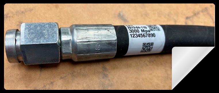
THE LABEL PLACEMENT
Label placement on the hose is critical and should be adjacent to the coupling which provides a firm rigid area without bending and compromising the label. In addition many current users place 1 label at each end of the hose insuring that there will be 1 label with good access when it comes time to read the bar code or identify the part number.
HOSE COVERINGS & PROTECTIVE ADD ONS
Many times hoses that are in precarious position or vulnerable to abrasion etc. are covered with a protective covering made out of a sheath of cloth, or other material
preventing the hose to scrape or be com promised. In these cases you typically see another sacrificial label applied to the protective covering that can be seen without removing the covering.
RFID TAGS
Radio Frequency Identification (RFID) technology is becoming increasingly used in the marketplace with the cost of implementing dropping. It is becoming mandatory in certain large box retailers such as Wal-Mart, Dicks, Home Depot etc.
The next generation of Smart Labels probably will contain a RFID tag or a NFC label which probably is in the .30- .50 each price range and requires a more expensive printer to encode the tags, and, in the case of RFID tag, requires a specialized RFID reader as well.
The RFID tags need to be printed on similar Thermal Transfer printers but with special RFID capability . (Printers $1900-$2800). The label contains an antenna or chip that needs to have the data encoded. The labels are then applied as normal labels are.
The RFID tags can only be read with a RFID reader or scanner ($1800-$2400).
NOTE: this can be the game changer since it would require anyone in the field to have access to such a reader.
CHALLENGE: Because the RFID hose tags maybe in close proximity to heavy iron, or behind enclosed areas the readability maybe a huge challenge and would need to be thoroughly tested.
The retailer can walk down an isle, scan the shelf and get valuable inventory information. That simply isn’t the case with heavy equipment in the field.
If this is something you want to implement I would strongly recommend a solution provider that can provide the Total Solution, the printer, software, labels, ribbons and support needed to keep you supported during this project. •
Air Compressors
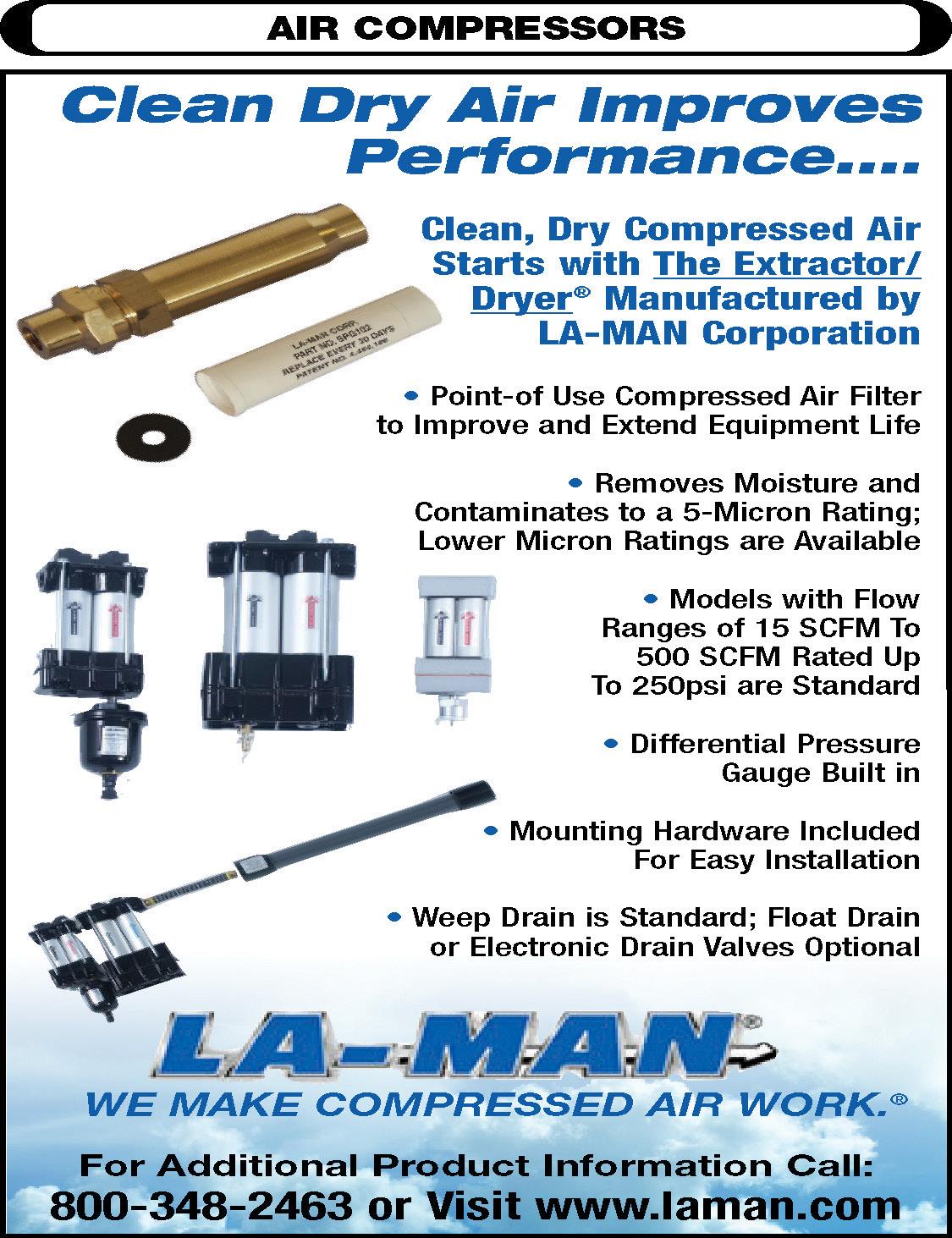
Clean Dry Air Improves Performance...
Clean, Dry Compressed Air Starts with The Extractor/Dryer® Manufactured by LA-MAn Corporation
• Point of Use Compressed Air Filter to Improve and Extend Equipment Life
• Removes Moisture and Contaminates to a 5-Micron Rating: Lower Micron Ratings are Available
• Models with Flow Ranges of 15 SCFM to 500 SCFM Rated Up To 250psi are Standard
• Differential Pressure Gauge Built in
• Mounting Hardware Included for Easy Installation
• Weep Drain is Standard; Float Drain or Electronic Drain Valves Optional
DETERMINING THE SOLUTION TO CONTROL AIR CYLINDER SPEED
Because air is a compressible fluid, controlling the speed of actuators is a unique problem. A pressurized air cylinder that is not under load will extend and/or return suddenly if the exhaust air is not controlled. This is often the case and is not likely to cause damage since most air cylinders are engineered with shock pads, or incorporate external stops on the cylinder rod to prevent the piston from bottoming internally against the head and cap ends. Unlike hydraulics, most pneumatic applications require full extension or full retraction without an intermediate position.
is required or load forces vary widely, 60-70% should not be exceeded, perhaps no more than 50% in vertical applications.
A positive speed control is obtained by throttling the inlet or exhaust air of the cylinder by means of a speed controller, which is a combination of a check valve, to allow free flow towards the cylinder, and an adjustable throttle (needle valve).
Energy Tip: While increasing the supply pressure may cause the acceleration rate to increase, it is done at a higher energy cost. Acceleration requirements need to be evaluated and when slower acceleration will work then doing so will save energy costs.
the cylinder, a quick exhaust valve may be employed. The quick exhaust valve connects directly to the cylinder port and allows for a large volume of air to exit the cylinder quickly to prevent dampened response times.
Safety Tip: Because oil mist is a potential hazard to personnel and OSHA mandates allowable exposure limits, the use of a coalescing muffler after the quick exhaust valve may be necessary.
It is necessary to understand the load dynamics that are present and to calculate the Load Ratio (LR) to achieve accurate speed control. This extra force, beyond the load force requirements, determines how fast the load can accelerate.
EQ 2.16 Load Ratio Equation Variables U.S. Customary Metric
Factual
LR= × 100
Ftheoretical LR = Load ratio
Factual = Actual force required to balance load
Ftheoretical = Theoretical force produced based on pressure and bore size at cylinder %= × 100 lbs lbs %= × 100 N N
The load ratio should never exceed approximately 85%. The lower the load ratio, the better the speed control, especially when the load is subject to variations. To get a constant speed, the Load Ratio should be approximately 75% or less. If accurate speed control
Metering out is a common method for controlling double acting cylinders. This is not to say that air cannot be metered into a cylinder to control velocity. However, unless a constant restrictive load is being moved, the cylinder will lurch as air pressure builds to the requirement of the load and then the air expands suddenly in the cylinder, dropping the pressure, only to repeat the process and lurch again.
In some instances, the cylinder speed can be adversely impacted by the resistance created by the tubing and valving connected to the cylinder. To prevent the restriction of flow from delaying the response time of
The rpm of air motors, on the other hand, is commonly controlled by the pressure at the inlet. Many air motors power constant loads, so it is as effective to regulate the inlet pressure as it is to provide a restriction at the inlet or outlet that wastes power needlessly.
Fig. 3-11 illustrates a double-acting cylinder mounted vertically with a load hanging on the cylinder rod. If the flow controls (1.1 & 1.2)
Fig. 3-11 Velocity Control For An Air Cylinder
were to be reversed for “meter-in” control, the load would drop suddenly when the solenoid valve is signalled to lower the load. “Meter-in” flow control would cause uncontrollable lowering and a hazardous condition.
Notice there are flow control valves in each cylinder line of the circuit to control the velocity. Each flow control valve allows air to pass freely in one direction and to be restricted in the other. As the valves are configured in the circuit, shifting the power valve to raise the load allows free flow of air through the check valve to the rod end of the cylinder to lift the load. The flow from the cap end is restricted back through the control valve to prevent the cylinder from retracting suddenly should the load be removed. Shifting the directional control valve to extend the cylinder and lower the load directs air to the cap end of the cylinder through the check valve. Return air from the rod end of the cylinder must pass through the restriction, preventing the load from dropping suddenly. This is a meter-out circuit.
Safety Tip: Installed system valves should never be the sole means of supporting a load or preventing inadvertent actuator movement. Use approved mechanical locking devices when required.
TEST YOUR SKILLS
Referring to Fig. 3-11, which valve configuration would require the lowest pressure while the load is being lifted?
A. Remove the flow control at valve 1.2.
B. Reverse flow control check at valve 1.1.
C. Reverse flow control check at valve 1.2.
D. Reverse flow control checks at valves 1.1 and 1.2.
E. Leave flow control valves 1.1 and 1.2 as they are.
See page 25 for the solution.
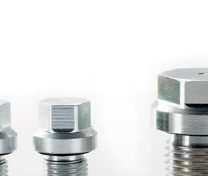
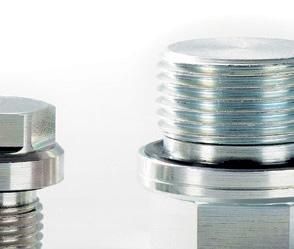
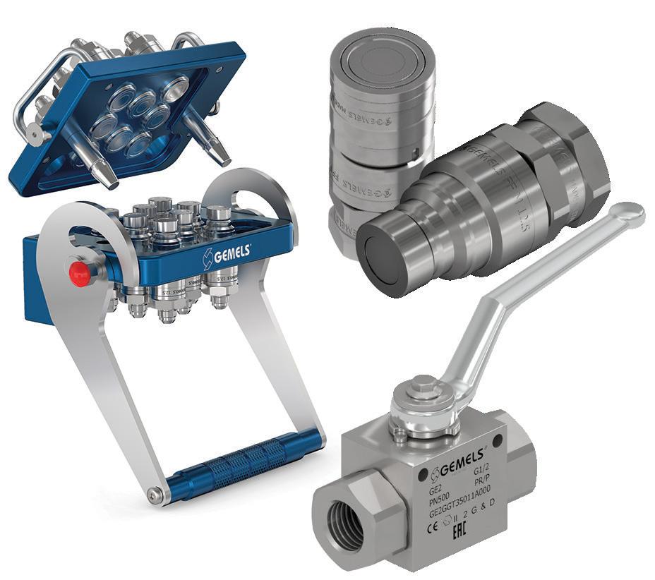
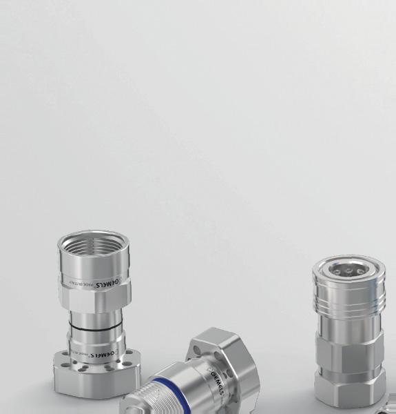
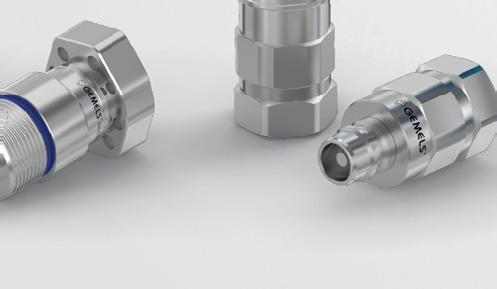
efficient reliable tight
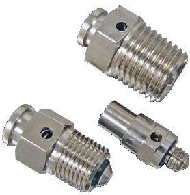
Plugs with integrated molded NBR or FKM seal. Automatically assembled with integrated control. Our products can be found worldwide in hydraulic applications and drive technology. We stock for you.
Hydraulic System Efficiency Maximizing
TWO COMMON WAYS TO CALCULATE THE APPROPRIATE COOLING CAPACITY REQUIREMENT OF HYDRAULIC SYSTEM
By Erick Espinosa, Technical Sales Manager, asa Hydraulik of America
Hydraulic systems play an integral role in numerous industrial, mobile, and many other hydraulic applications, serving as a vital component for a wide array of equipment ranging from a small hydraulic power unit to heavy industrial and mobile pieces of machinery. Despite its advantages, the optimal performance of a hydraulic system hinges on several key factors, one of which is maintaining the hydraulic fluid at the appropriate operating temperatures.
Hydraulic systems are not 100% efficient due to efficiency losses in various components of the hydraulic system. Typically, pumps and motors have efficiency losses and valves produce regulating losses. These combined losses will produce heat.
It is important to note that for a typical hydraulic fluid with the recommended operating temperature of 40°C (104°F), for every 8°C (14°F) rise in temperature, oil service life may be reduced by 50%. Due to atmospheric pressure, typically hydraulic fluid may contain up to 9% air at 20°C (68°F), and at 60°C (140°F), this air content may increase to 14% leading to potential cavitation.
The hydraulic fluid's operating temperature is important as it directly influences its viscosity, lubricating properties, and overall effectiveness within the system.
Maximum and Minimum Oil Viscosity Recommended by Pump and Motor Manufacturers
• V min. 8-10 cSt short period in discharge line
• V max. 1.000 cSt short period in suction line
• Optimum operating viscosity
• V optimum ~ 30 cSt (pump performance is generally estimated at 30 cSt)
Maximum and Minimum Oil Viscosity Recommended by Pump and Motor Manufacturers
Fluctuations in temperature can lead to viscosity changes, affecting the fluid's ability to flow smoothly and lubricate components properly. This, in turn, can result in cavitation, leakage, increased wear and tear on system components, and potential system failures.
Where is heat generated?
Understanding the intricacies of hydraulic system heat generation is critical for maintaining the efficiency of the hydraulic machinery. Heat generation within a hydraulic system is a consequence of the conversion of mechanical energy into thermal energy as the hydraulic fluid circulates through the system. This process occurs due to several contributing factors, each playing a significant role in the overall heat generation process. Fluid friction, one of the primary contributors to heat generation, occurs as hydraulic fluid encounters resistance while flowing through the system. This resistance is caused by the interaction between the fluid and internal components such as valves, hoses, fittings, and the surfaces of tubes or cylinders. The energy expended to overcome this
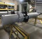
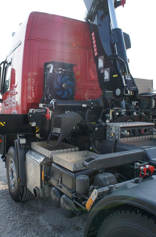
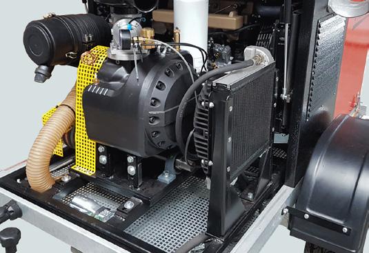
Sample of Hydraulic Systems
friction is converted into heat, gradually raising the temperature of the hydraulic fluid and the surrounding components.
Pressure changes within the hydraulic system also contribute to heat generation. When the system experiences rapid changes in pressure, such as during pump operation or valve manipulation, the hydraulic fluid undergoes adiabatic compression or expansion. This compression and expansion process increases the fluid's temperature, further contributing to heat generation within the system. Furthermore, the efficiency of hydraulic components themselves can impact heat generation. Inefficient components, such as pumps, motors, and valves, may generate excess heat due to internal losses resulting from friction, leakage, or inefficient fluid displacement. These inefficiencies not only reduce the overall efficiency of the hydraulic system but also contribute to increased heat generation, potentially leading to accelerated wear and reduced component lifespan.
External factors, such as environmental conditions, also play a role in heat generation within hydraulic systems. High ambient temperatures, exposure to direct sunlight, or inadequate ventilation can elevate the temperature of the hydraulic fluid and components, aggravating heat generation and potentially compromising system performance and reliability.
How to determine the cooling capacity?
To solve this important aspect of hydraulic system operation, we will discuss the two common ways of determining the cooling capacity required to maintain optimal operating temperature. By understanding the factors influencing temperature regulation and calculating its cooling requirement, we can now find ways to implement an effective cooling solution. With this, we can enhance the efficiency, reliability, and uptime of hydraulic systems. With the knowledge of the factors that generate heat in a hydraulic system, we should now focus on how much cooling is required to mitigate this temperature surge.
In a hydraulic system, the formula for calculating the heat rejection requirement can be expressed as:
P M = required motor power (kW)
p = oil pressure (MPa)
= p × Qp
PK = PM (1 - η)
QP = oil flow (lpm)
K = conversion factor (60)
η = pump efficiency 0.70-0.80
PK = required cooling (kW)
PM = required power (kW)
η = general efficiency
PM = required motor power (hp)
p = oil pressure (psi)
QP = oil flow (gpm)
K = conversion factor (1714)
η = pump efficiency 0.70-0.80
PK = required cooling (hp)
PM = required power (hp)
η = general efficiency
Hydraulic system with constant pumps has a general efficiency from approximately 70-75%. η = 0.7 to 0.75 / circuits with variable pumps: η = 0.75 to 0.80.
For the hydraulic system to be effective, we should maintain thermal balance within the system. This means the heat dissipated is equivalent to the heat generated.
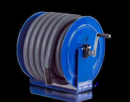
quality matters.
HOSE, CORD, & CABLE PRO GRADE REELS
Equation Metric US Customary
Thermal Balance Heat Balance is achieved eventually when oil temperature equalizes with ambient air temperature. But at what temperature?
The cooling capacity requirement can be determined through various methods; below are two of the most common ways to calculate cooling capacity, each offering unique insights into system optimization.
“Installed Power Method”
Calculating the cooling capacity by this method is the most common way of determining the requirement. This method can be used for newly designed systems or an existing system.
In this method, a percentage of installed power is considered to produce losses that will generate heat. This percentage depends on the system and how complex it is, and the losses could be anywhere from 25% to 50%. The most common rule of thumb is about 1/3 (33%) of installed power is considered a cooling capacity requirement. Installed power in a system is the primary electric motor(s) power rating.
A percentage of the above-installed power (25%-35%) is then assumed to be the system inefficiency that is converted into heat that needs to be dissipated.
For example; we have an installed power of (PM) 40kW (54 hp) and an assumed system inefficiency of (η) 33%; we can determine the required cooling performance (PK);
First, we assumed 1−η to be 33% = 0.33
Next, we multiply the required motor power by this result:
PK = 40 kW × 0.33 = 13.2 (54 hp x 0.33 = 17.8 hp)
Therefore, the required cooling performance is 13.2 kW (17.8 hp). This means that to maintain the system's optimal operating temperature, a cooling capacity of 13.2 kW (17.8 hp) is required to dissipate the excess heat generated by the 40 kW (54 hp) system with an inefficiency of 33%.
“Field Testing Method”
The "Field Testing or Warm-Up Method" is the most accurate way of measuring the heat losses for an existing hydraulic system. This method involves running the hydraulic system at maximum load for a specified period while monitoring various parameters to calculate the amount of heat generated.
This test must be conducted ideally when the system is shut down for several hours allowing the hydraulic fluid in the tank to reach ambient temperature. Any existing heat exchanger in the system must be isolated or turned off before this test. The total hydraulic fluid volume must be recorded. If the fluid is anything different than standard hydraulic fluid, we need to consider that in our calculation since the specific heat and density may be different which could lead to different results in the heat load calculation.
Next, we should identify the Maximum Load: Determine the maximum load that the hydraulic system will undergo during operation. This will be considered using different factors, either by the maximum pressure, flow rate, or a combination of both, depending on the application. This test must be conducted at maximum load to ensure we collect data based on the worst-case scenario.
Install sensors and monitoring equipment to measure the following parameters:
• Hydraulic fluid temperature before start-up. °C (°F). (t1)
• Hydraulic fluid temperature at the end of the test °C (°F) (t2)
• Volume of the hydraulic fluid in Liters (gallons) (V)
• Specific Heat Capacity of the Hydraulic Fluid kJ/kg °C (°F) (cp)
• Density of the Fluid g/cm³ (slug/ft³) (ρ)
• Time elapsed in minutes (T)
Start the Warm-Up Process: Operate the system first at a lower pressure and flow. This will give time for the hydraulic fluid to circulate through the whole system. Next, slowly increase the load until it reaches the identified maximum load. Run the hydraulic equipment normally including maximum
P = ((t2 - t1) × V × Cp × p) (T × K)
P = power (kW)
t2 = final temperature (°C)
t1 = initial temperature (°C)
V = volume of fluid (liters)
C p = specific heat (kj/kg °C)
p = density (g/cm³)
T = time in minutes
K = conversion factor (60)
P = power (hp)
t2 = final temperature (°F)
t1 = initial temperature (°F)
V = volume of fluid (gallons)
C p = specific heat (kj/kg °F)
p = density (slug/ft³)
T = time in minutes
K = conversion factor (317.245)
being more expensive initially than water/oil heat exchangers, generating noise, and their performance is sensitive to fluctuations in ambient air temperature.
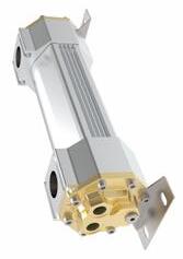
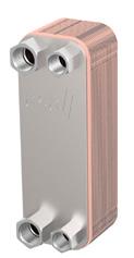
On the other hand, water/oil heat exchangers have their own set of advantages, such as being smaller in size, operating quietly, maintaining
low-temperature variations, and the possibility of reutilizing heated water. They also eliminate the risk of emitting heat into the atmosphere and provide consistent performance regardless of ambient air temperature. However, they come with some disadvantages, including higher installation costs, the need for a clean
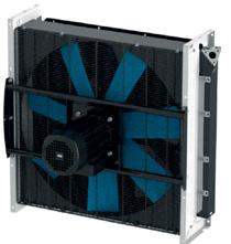
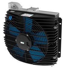
water supply, the risk of corrosion, and potential contamination issues. Additionally, they require the cost of water usage, which can add to operational expenses. Air-Oil Heat Exchangers
Heat exchangers offer versatility, adapting seamlessly to various environments and operating conditions. Their reliability and effectiveness make them indispensable components in hydraulic systems, enhancing performance and longevity. In summary, while both passive and active cooling methods play vital roles, heat exchangers emerge as indispensable assets, offering unparalleled efficiency and reliability in managing excess heat within hydraulic systems.
Hydraulic systems continue to evolve with advancements in technology and innovation, and new materials, innovative designs, and cooling techniques may emerge to address the evolving demands of modern hydraulic applications. By staying abreast of these developments and adapting cooling strategies accordingly, we can maximize the performance and reliability of hydraulic systems while minimizing downtime and maintenance costs. • continued from page 15
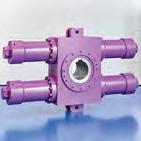
Sample of air/oil exchangers
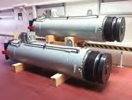
Sample of water/oil exchangers
Hydraulic and Pneumatic Industry Trends With NFPA
» THE LATEST DATA published by the National Fluid Power Association shows May 2024 total fluid power shipments decreasing -0.6% month over month and -11.2% year over year. 12/12 rates of change for total fluid power, hydraulic, and pneumatic shipments are all negative and trending downwards. The data and charts above are from NFPA’s Confidential Shipment Statistics (CSS) program where over 70 manufacturers of fluid power products report their monthly orders and shipments. More market information is available to NFPA members, allowing them to better understand trends and anticipate change in fluid power and the many customer markets it serves. Contact NFPA at 414-778-3344 for more info.
TOTAL FLUID POWER SHIPMENTS
INDEX DATA: 3 MONTH MOVING AVERAGE & 12 MONTH MOVING AVERAGE
This graph of index data is generated by the total dollar volume reported to NFPA by CSS participants. This graph uses moving averages to smooth out the data and clearly identify trends. (Base Year 2018 = 100).
SHIPMENTS: PNEUMATIC, MOBILE HYDRAULIC, AND INDUSTRIAL HYDRAULIC
INDEX DATA: 12/12 RATE OF CHANGE
Each point on this graph represents the most recent 12 months of shipments compared to the previous 12 months of shipments. For example, 7.3% (the August 2023 level of the pneumatic series) indicates that the value of pneumatic shipments from September 2022 to August 2023 were 7.3% higher than the value of pneumatic shipments from September 2021 to August 2022.
ORDERS: PNEUMATIC, MOBILE HYDRAULIC, AND INDUSTRIAL HYDRAULIC
INDEX DATA: 12/12 RATE OF CHANGE
Each point on this graph represents the most recent 12 months of orders compared to the previous 12 months of orders. For example, 8.5% (the August 2023 level of the industrial hydraulic series) indicates that the value of industrial hydraulic orders received from September 2022 to August 2023 were 8.5% higher than the value of industrial hydraulic orders received from September 2021 to August 2022.
TOTAL SHIPMENTS: SEPTEMBER 2023
This table shows various rates of change for the month of August 2023. Interpretation for each rate of change calculation:
M/M %: The percent change between the current month and the previous month.
Y/Y %: The percent change between the current month and the same month one year ago.
3/12 %: The percent change between the three most recent months and those same three months one year ago. 12/12 %: The percent change between the twelve most recent months and those same twelve months one year ago.
*Preliminary data subject to revision.
2024 Annual Meeting & Hall of Fame Ceremony
» JOIN US SEPTEMBER 30th - October 3rd in Kansas City, MO or virtually, for the IFPS Annual Meeting & Fluid Power Hall of Fame Ceremony recognizing Robert Scheaf Jr. & Constantine (Connie) Kosarzecki! IFPS Meetings bring together industry professionals, experts, and enthusiasts from the fluid power industry, providing a platform for networking, knowledge sharing, and collaboration. Visit https://ifps.org/meetings to register, view the schedule of events and technical workshop, or book your hotel.
TECHNICAL WORKSHOP
Join Ken Dulinski, CFPAI, as he presents an overview of the newly revised and upgraded ECS study manual. Ken will provide a detailed look at the updated text and graphics within the manual. This workshop aims to prepare you for successfully attaining the ECS certification and will also be beneficial for any AIs interested in training or preparing a test candidate for the newly updated ECS. In addition, this workshop will highlight the significant benefits of pursuing the ECS certification, especially if you already hold the PS or HS certification.
TOURS & EVENTS
DINNER AT CHAR BAR
MONDAY, SEPTEMBER 30TH
Kansas City BBQ & Southern eats with a modern twist in a big space with a beer garden with games.
ALTEC INDUSTRIES TOUR
TUESDAY, OCTOBER 1ST
A behind-the-scenes look at one of Altec Industries' largest manufacturing facilities – Altec is a leading provider of products and services to electric utility, telecommunications, tree care, lights and signs, and contractor markets.
COCKTAILS AND TAPAS AT TIN ROOF BAR
TUESDAY, OCTOBER 1ST
Live music bar & restaurant located in Kansas City’s Westport neighborhood. Large patio, delicious food, drinks & entertainment.
ARABIA STEAMBOAT MUSEUM
WEDNESDAY, OCTOBER 2ND
The Arabia Steamboat Museum is a history museum in Kansas City, Missouri, housing artifacts salvaged from the Arabia, a steamboat that sank in the Missouri River in 1856. The 30,000-square-foot museum opened on November 13, 1993.
Newly Certified Professionals JUNE 2024
AJPPCC
Jonathan Cochran, Custom Hydraulics & Design, Inc.
CONNECTOR & CONDUCTOR
Corin Croswell, The Boeing Company
Damon Frashure, The Boeing Company
Laura Pollack, The Boeing Company
Michael Jordan, The Boeing Company
Ryan Long, The Boeing Company
ELECTRONIC CONTROL SPECIALIST
Charley Shin, The Boeing Company
Paul Turner, Altec Industries, Inc.
ENGINEER
Ashwin Shridhar, Applied Industrial Technologies
HYDRAULIC SPECIALIST
Alexandria Park
Brandon Godsey, John Henry Foster
Brian Salentine, Applied Industrial Technologies
Jon Glass, John Henry Foster Company
Jacob Moser, GCC, Inc
Marc Dobbyn
Matthew Hitzemann, John Henry Foster Company
Nathan Black, John Henry Foster Company
Nic Surgnier, GCC
Robert Mudd, John Henry Foster Company
Ryan Williams, John Henry Foster Company
Mobile Hydraulic Mechanic
Andrew Adkins, The Illuminating Company
Alex Elgas, Tacoma Fire
Basil Gardner, Altec Industries, Inc.
Brian Stewart, Georgia Power
Caleb Copeland, Georgia Power
Caleb Teague, Georgia power
Coby Workinger , Grant County PUD
Daniel Helmey, Georgia Power
Daniel Sadowski, The Illuminating Company
Ford Hindbaugh , Grays Harbor PUD
Garrett Coon, Altec Industries, Inc.
Glenn Dennis, Georgia Power
Heather Leithead
Jacob Rice, Georgia power
Jim Bergin, Tacoma Fire
Jeff Bader, Idaho Power
John Robison
Kobi Thomas, Mountain Parks Electric
Mickey Morris, Georgia Power
Nick Corey, Tacoma Fire
Rafael Beltran , Altec Industries, Inc.
Stephen Wallis, Georgia Power Company
Terry Robinson
Michael Fox, Altec Industries, Inc.
Zachary Smith , Georgia Power
Zayne Waits, Georgia Power
PNEUMATIC SPECIALST
Chet Wilson, Gerdau
Gabi Brodfehrer, Clippard
Mark Jorgensen
Michel Domenella, Clippard
Noman Sadi, Clippard
Wesley Eppley, Hydrotech, Inc.
William Long, Gerdau
SPECIALIST
Chet Wilson, Gerdau
Mark Jorgensen
Wesley Eppley, Hydrotech, Inc.
William Long, Gerdau
Customize An In-Person or Virtual Training Program!
» ELEVATE YOUR CERTIFICATION preparation with our Custom Review Training programs! IFPS provides flexible training options, both in-person and virtual, for groups of all sizes. Our expert instructors cover a wide range of fluid power and motion control topics, enabling you
to tailor the training to meet your team's specific needs. Work with our team to coordinate the perfect session that fits you and your team’s schedule. Scan here to learn more
Waukashau Fluid Power Fundamentals Course is Back!
» ONLY 30 SPOTS available! The Fluid Power Society is partnering with Waukesha County Technical College to host our second Fluid Power Fundamentals course! This event is highly sought after by both entry-level and experienced fluid power professionals looking to enhance their knowledge of Fluid Power Basics, and it's expected to fill up quickly! WHO SHOULD ATTEND: Anyone who would like an introduction to fluid power and the components that make up a system (i.e. Customer service representatives, engineers, maintenance technicians, and interested associates.)
WHERE WILL THE VIRTUAL CLASSES BE HELD? Classes will be held online with labs and streamed demonstrations. They will be held from 1:30-3:30pm CENTRAL time on the following dates: 10/22, 10/24, 10/29, 10/31, 11/5, 11/7, 11/12, 11/14.
WHAT IS THE COST:
• IFPS Members: $299
• Non-IFPS Members: $399
WHAT IS REQUIRED: An internet connection, zoom, pencil(s) and paper for taking notes, and a simple math calculator (i.e. TI-30).
Attendees will receive:
• 1.6 CEU's
• Certificate of Completion from Waukesha County Technical College
• Danfoss "Elementary Hydraulics" Student Guide.
Week 1 - Introduction to Fluid Power
Week 2 - Hydraulic Fluids
Week 3 - Fluid Conductors & Seals
Week 4 - Hydraulic Actuators
Week 5 - Directional Control Valves
Week 6 - Pressure Control Valves
Week 7 - Hyd. Pumps and Motors
Week 8 - Reservoirs and Review
WHEN IS THE
REGISTRATION DEADLINE?
October 16, 2024 Scan here to register
Digital Documents reverse-engineer systems cross/type components
Photo Navigation drilling down to individual components & parts
Interactive Prints illustrate machine operations & functions
Video Troubleshoot capture tribal knowledge & train on-the-job Can Work Offline on any device browser
Individuals wishing to take any IFPS written certification tests can select from convenient locations across the United States and Canada. IFPS is able to offer these locations through its affiliation with the Consortium of College Testing Centers provided by National College Testing Association. Contact Kyle Pollander at Kpollander@ifps.org if you do not see a location near you. Every effort will be made to accommodate your needs.
Written Certification Test Locations
Alabama Auburn, AL Birmingham, AL Calera, AL Decatur, AL Huntsville, AL Jacksonville, AL Mobile, AL Montgomery, AL Normal, AL Tuscaloosa, AL Alaska Anchorage, AK Fairbanks, AK
Arizona Flagstaff, AZ Glendale, AZ Mesa, AZ Phoenix, AZ Prescott, AZ Scottsdale, AZ
Sierra Vista, AZ Tempe, AZ Thatcher, AZ Tucson, AZ Yuma, AZ
Arkansas Bentonville, AR Hot Springs, AR Little Rock, AR
TENTATIVE TESTING DATES FOR ALL LOCATIONS
SEPTEMBER 2024
Tuesday 9/10 • Thursday 9/26
OCTOBER 2024
Tuesday 10/8 • Thursday 10/24
NOVEMBER 2024
Tuesday 11/4 • Thursday 11/21
DECEMBER 2024
Tuesday 12/9 • Thursday 12/19
California Aptos, CA Arcata, CA Bakersfield, CA Dixon, CA Encinitas, CA Fresno, CA Irvine, CA Marysville, CA Riverside, CA Salinas, CA San Diego, CA San Jose, CA San Luis Obispo, CA Santa Ana, CA Santa Maria, CA Santa Rosa, CA Tustin, CA Yucaipa, CA
Colorado Aurora, CO Boulder, CO Springs, CO Denver, CO
Durango, CO Ft. Collins, CO Greeley, CO Lakewood, CO Littleton, CO Pueblo, CO
JOB PERFORMANCE TEST LOCATIONS
Arizona California Colorado Florida Georgia Maine Michigan Minnesota Montana New Jersey Nova Scotia Pennsylvania Texas Washington Wyoming Western Australia
Delaware Dover, DE Georgetown, DE Newark, DE
Florida Avon Park, FL Boca Raton, FL Cocoa, FL Davie, FL Daytona Beach, FL Fort Pierce, FL Ft. Myers, FL
Master of Industrial Hydraulics (Must Obtain CFPIHM, CFPIHT, & CFPCC)
CFPMMH
Certified Fluid Power
Master of Mobile Hydraulics (Must Obtain CFPMHM, CFPMHT, & CFPCC)
CFPMIP
Certified Fluid Power
Master of Industrial Pneumatics
(Must Obtain CFPPM, CFPPT, & CFPCC)
CFPCC
Certified Fluid Power Connector & Conductor
CFPSD Fluid Power System Designer
Tentative Certification Review Training
IFPS offers onsite review training for small groups of at least 10 persons. An IFPS accredited instructor visits your company to conduct the review. Contact kpollander@ifps.org for details of the scheduled onsite reviews listed below.
HYDRAULIC SPECIALIST
2024 certification review training dates will be announced soon.
For custom IFPS training inquiries, please contact Bj Wagner (bwagner@ifps.org)
ELECTRONIC CONTROLS SPECIALIST
For custom IFPS training inquiries, please contact Bj Wagner (bwagner@ifps.org).
For dates, call CFC Industrial Training at (513) 874-3225 or visit www.cfcindustrialtraining.com.
PNEUMATIC SPECIALIST
2024 certification review training dates will be announced soon.
For custom IFPS training inquiries, please contact Bj Wagner (bwagner@ifps.org)
CONNECTOR & CONDUCTOR
2024 certification review training dates will be announced soon.
For custom IFPS training inquiries, please contact Bj Wagner (bwagner@ifps.org).
MOBILE HYDRAULIC MECHANIC
2024 certification review training dates will be announced soon.
For custom training IFPS inquiries, please contact Bj Wagner (bwagner@ifps.org)
Online Mobile Hydraulic Mechanic certification review for written test is offered through CFC Industrial Training. This course surveys the MHM Study Manual (6.5 hours) and every outcome to prepare you for the written test. Members may e-mail for a 20% coupon code off the list price. Test fees are not included.
» CFC Industrial Training – Cincinnati, Ohio – December 2-6, 2024
INDUSTRIAL HYDRAULIC MECHANIC
For custom IFPS training inquiries, please contact Bj Wagner (bwagner@ifps.org).
For dates, call CFC Industrial Training at (513) 874-3225 or visit www.cfcindustrialtraining.com.
INDUSTRIAL HYDRAULIC TECHNICIAN
For custom IFPS training inquiries, please contact Bj Wagner (bwagner@ifps.org).
» For dates, call CFC Industrial Training at (513) 874-3225 or visit www.cfcindustrialtraining.com.
MOBILE HYDRAULIC TECHNICIAN
2024 certification review training dates will be announced soon. For custom IFPS training inquiries, please contact Bj Wagner (bwagner@ifps.org).
PNEUMATIC TECHNICIAN & PNEUMATIC MECHANIC
For custom IFPS training inquiries, please contact Bj Wagner (bwagner@ifps.org).
» For dates, call CFC Industrial Training at (513) 874-3225 or visit www.cfcindustrialtraining.com.
LITERATURE REVIEW
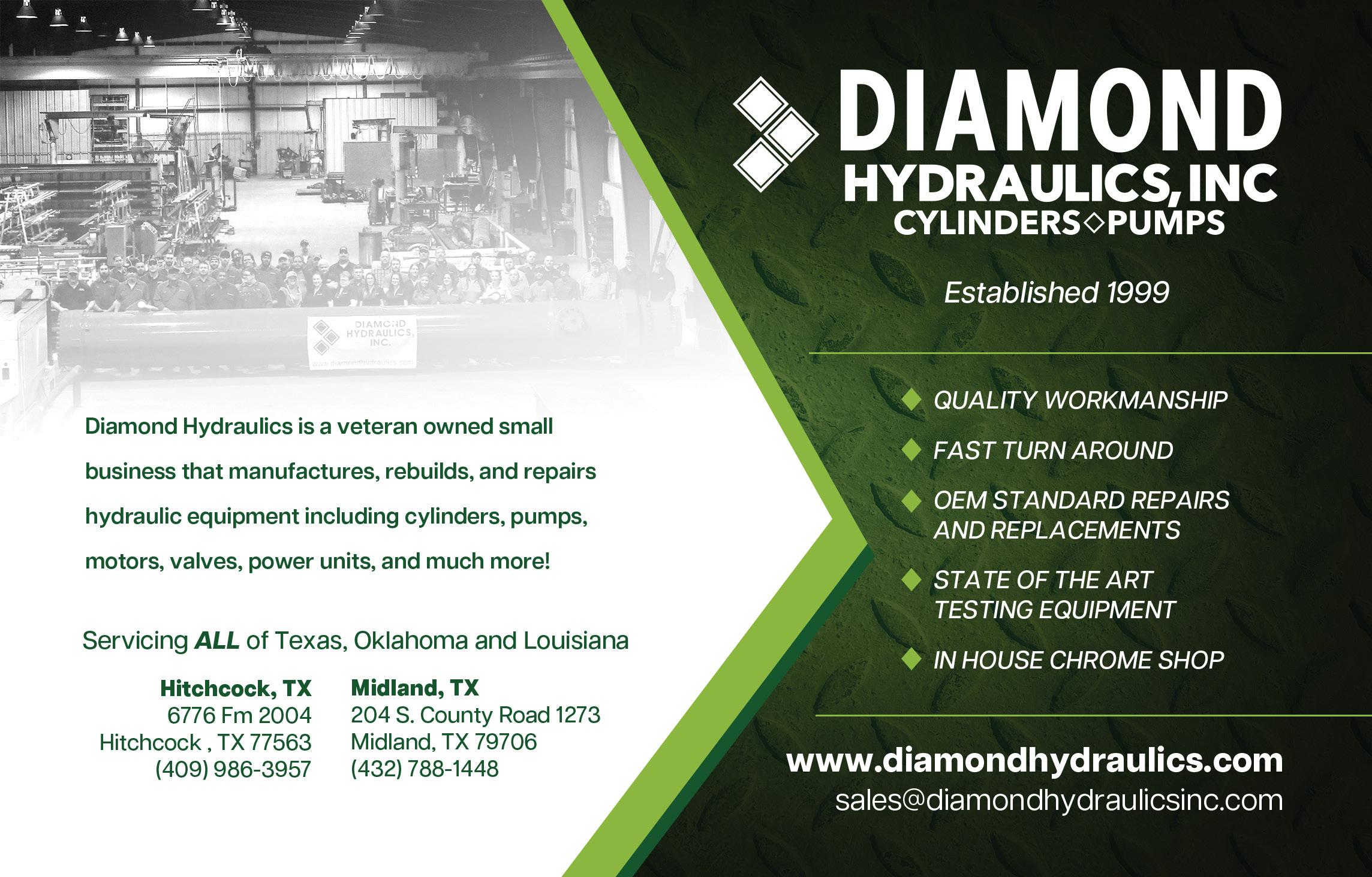
Diamond Hydraulics, Inc.
Diamond Hydraulics provides fast, accurate repair of hydraulic components by industry experts. With state-ofthe-art test equipment, we ensure that your products are in the absolute best condition before leaving our facility. We are committed to providing excellent customer service and strive to consistently meet and exceed the needs and expectations of every customer.
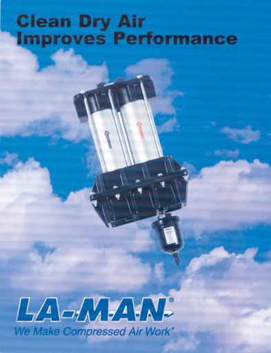
Brochure offers a comprehensive overview of the company’s complete line of compressed air filtration products. Highlighted is the patented family of Extractor/Dryers. These two-stage, point of use filters remove contaminates to a 5-micron rating with flow ranges of 15 to 2,000 scfm. Additional products available include the SuperStar Membrane Dryer, .01 Micron Filter, Refrigerated Extractor/Dryer, and much more.
La-Man Corporation
800.348.2463 www.laman.com
Solutions to Protect Hydraulic Hose & Fittings
Construction, agricultural and mining vehicles need to be durable and perform in the most demanding environments. We’ve put together this short guide to help design engineers, OEMs, and hydraulic designers choose the small components they’ll need to ensure reliable operations, reduced downtime, and low maintenance costs.
sales@essentracomponents.com
800-847-0486
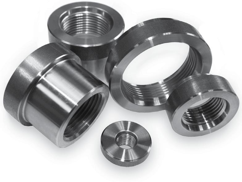
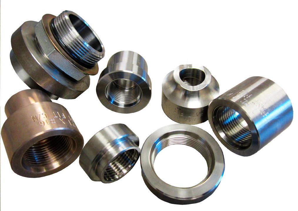
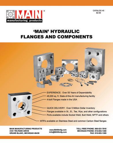
Hydraulic Flanges and Components
New 120 page catalog includes popular styles of MAIN Manufacturing’s extensive offering of carbon and stainless Hydraulic Flanges and Components – ready for immediate shipment. Metric ordering information, weld specs, and dimensional information included. The “Quick Reference Guide” helps specify less popular items often stocked or quickly manufactured (generally 3-4 days) at our US plant.
Dive into our latest whitepaper to explore the advantages and challenges of integrating ePump systems in mobile applications. Gain expert insights on designing efficient electrified systems and discover proved energy-saving strategies though an exclusive case study. Perfect for engineers looking to innovate towards electric power. Download now and revolutionize your machinery.
discover.parker.com/role-of-the-ePump
LITERATURE REVIEW
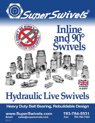
Hydraulic Live Swivels Catalog
Inline and 90° hydraulic live swivels.
Available in sizes from 1/8” to 2-1/2”, rated to 10,000 PSI, heat treated, superior quality alloy steel, chrome or stainless steel ball bearings, withstands heavy side loads, burnished (micro smooth) barrel bores, Viton®, Aflas®, or Teflon® encapsulated seals, zinc or nickel plated, available in 304 and 440 stainless steel, full flow - low pressure drop, rebuilding kits available.
Super Swivels
Phone: 763.784.5531
Fax: 763.784.7423
Website: www.superswivels.com
New and Improved Product Catalog
World Wide Metric’s updated CAST catalog features 358 pages of their fittings product line, along with technical information and drawings. Their wide selection includes DIN metric compression, JIC flared, BSP adaptors, coversion adaptors, ORFS, hose and hose fittings. Catalog can be downloaded on their website with print version available upon request. www.worldwidemetric.com sales@worldwidemetric.com 732-247-2300
PRODUCT SPOTLIGHT
PASSION TO PERFORM
PERFECT COMBINATION
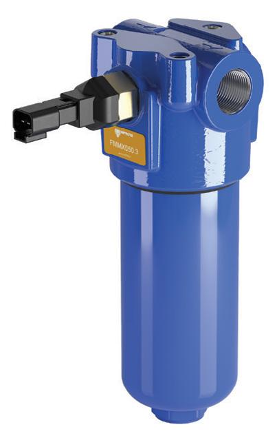
Take one FMMX050
high pressure in-line filter.
+ HPX050 MYclean element for proprietary OEM fit.
+ Zerospark® option to reduce electrostatic discharge.
= Highest standards of safety and quality for mobile equipment applications.
FMMX050:
Maximum working pressure 6090 psi and flow rate up to 41 gpm
MP Filtri USA, Inc. 1181 Richland Commerce Drive, Quakertown, PA 18951
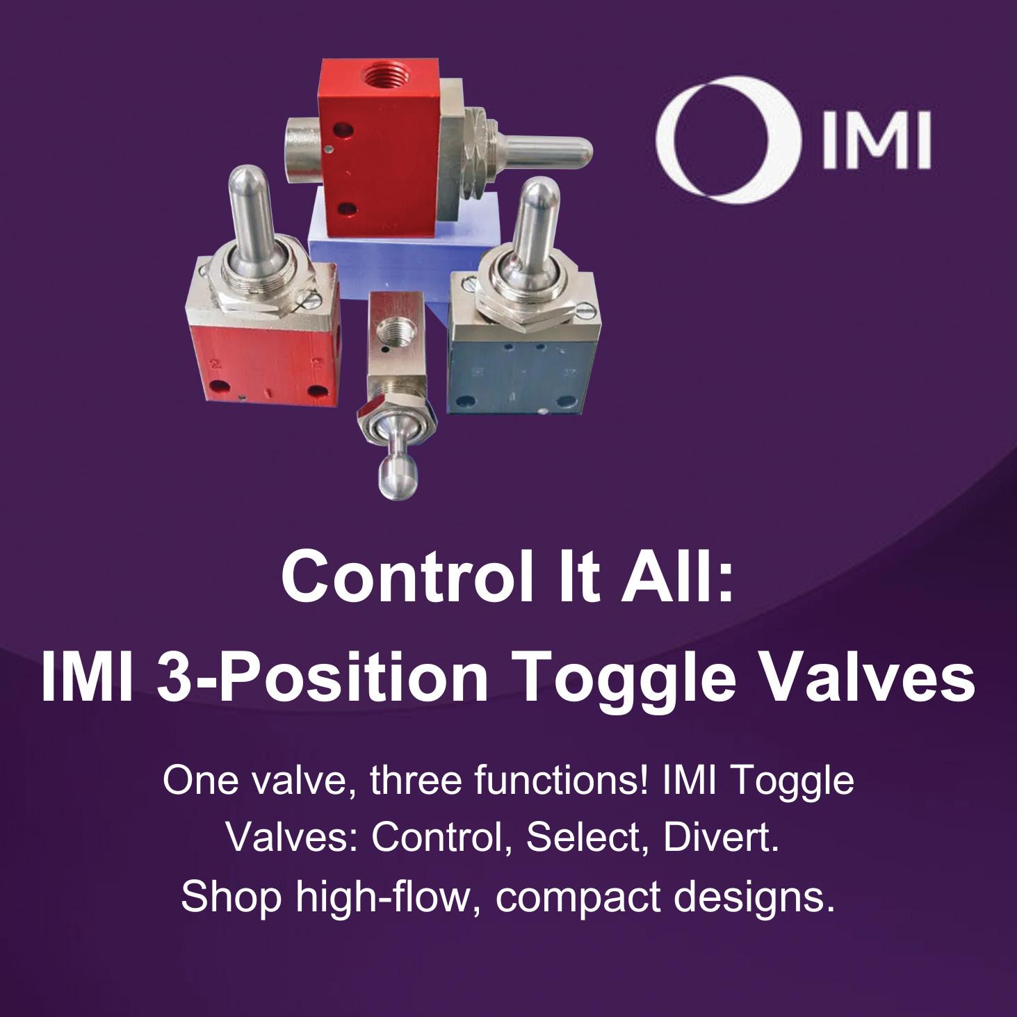
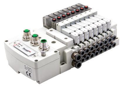
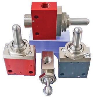
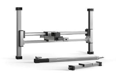
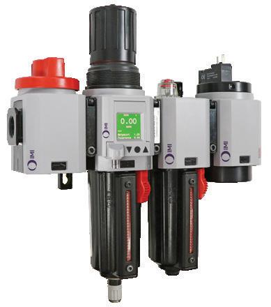
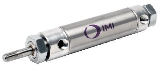
IMI solutions help to streamline your circuit ranging from basic manifolds like the IMI Norgren Pneumadyne® Series Valves to Ethernet-enabled VR Manifolds. These products regulate, direct, and control fluid flow by opening, closing, or partially obstructing passageways. Engineered for optimal performance, the wide range of valve offerings aim to enhance operational efficiency and integrate seamlessly into your systems.
IMI actuators, air preparation, and electric motion solutions are vital in optimizing industrial efficiency and precision. IMI actuators provide reliable movement control, air preparation that provides clean, regulated air for peak performance, and electric motion systems that deliver precise, adaptable automation. Together, they enhance productivity, ensure system reliability, and support innovative processes, driving excellence in motion control and fluid technology.
For more information, call (203) 861-9400 or email sales@flangelock.com. www.flangelock.com
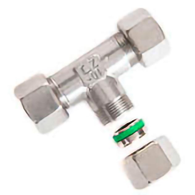
DIN Compression Fittings
World Wide Metric offers a wide selection of DIN 2353 compression fittings. These fittings are a high quality product used for fluid power systems joining tubes together. Available in carbon steel and stainless steel with sizes ranging from 4mm–42mm.
Contact them for more information www.worldwidemetric.com sales@worldwidemetric.com 732-247-2300
PRODUCT SPOTLIGHT
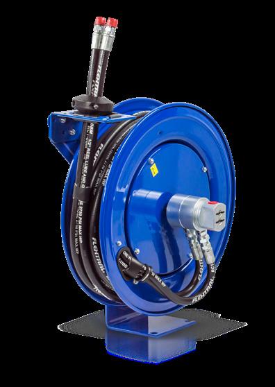
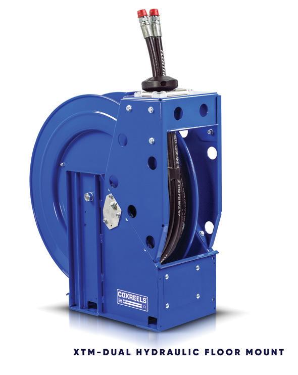
Coxreels® Extreme Duty
XTM Dual Hydraulic Reel!
XTM-DMP-450 is the most robust reel with triple axel support, twin-line fully bonded hose, and stainless-steel hose guide rollers. As with all Coxreels reels, it features heavy gauge steel construction, durable CPC powder coat, rolled and ribbed discs, and USA made. www.coxreels.com
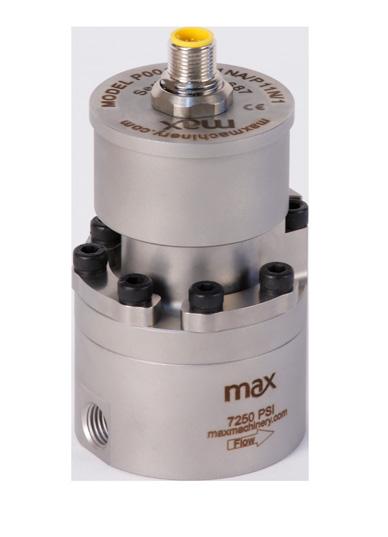
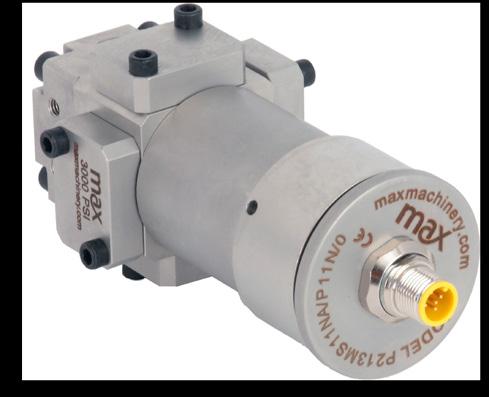
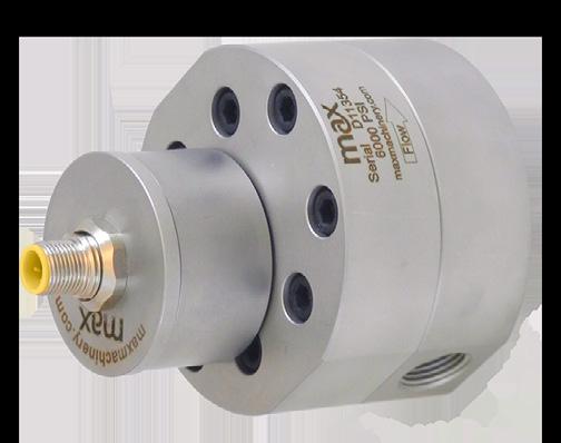
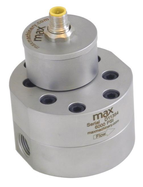
Precision Flow Meters
Max Machinery, Inc.
Skip counting teeth and join the revolution. By measuring the gear’s rotation, we can double your resolution and accuracy across all your process flows. From 1 cc/ min to 240 liters/min, Max Gear Meters provide 0.3% accuracy and data up to 500 pulses/cc. See what flow you’re missing and how to improve your process by using a Max Precision Gear Meter.
Max Machinery, Inc. 33A Healdsburg Ave. Healdsburg, CA 95448 707-433-2662 www.maxmachinery.com
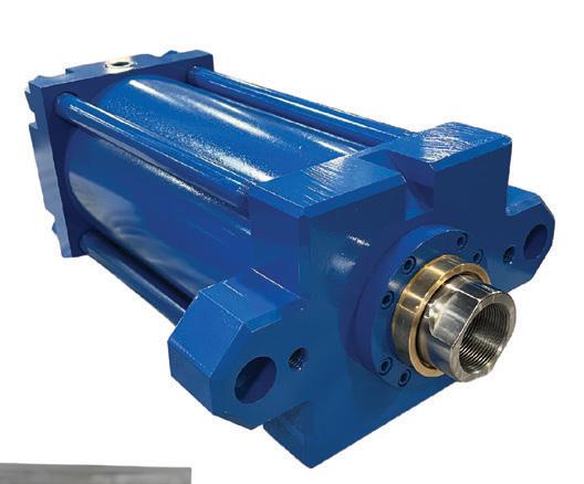
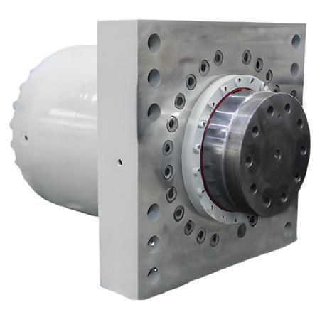
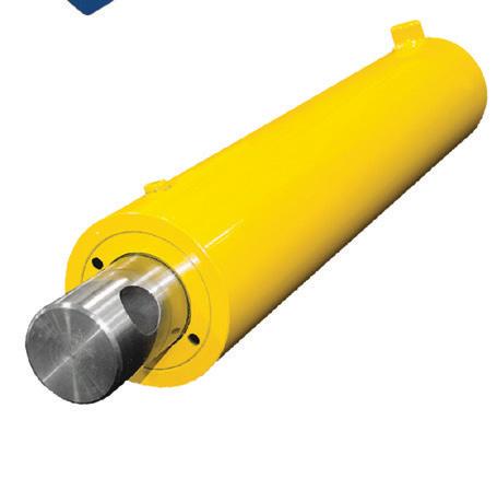
Think Yates Cylinders for ALL of your cylinder needs!
Custom Welded Cylinders:
• 1.5” up to 50” bore, with strokes exceeding 300”
Heavy Duty Mill Cylinders:
• 1.5” up to 50” bore, with strokes exceeding 300”
NFPA/JIC Tie Rod Cylinders:
• 1.5” up to 24” bore; interchangeable with all brands
» HERE IS THE SOLUTION TO FIGURE IT OUT ON PAGE 05
The circuit for the roll removal system is commonly called a part time Regen (regeneration) allowing the rod flow to join the pump flow moving the cylinder at a fast rate and when encountering a load, the speed would drop to a steady slow rate as the cap end pressure increased. The 1.3 mm (0.050”) orifice prevented the rod side pressure from intensifying and reducing the total extension force. The drawing showed a 0.5 mm (0.020”) orifice that was blocked causing this problem. Just another note, when they found the blocked orifice in a fitting, they also discovered it was a 1.3 mm (0.050”) size, and not as shown on the drawing. The builder must have changed it to a larger size to acquire the slower speed and the high force they needed.
The correct answers to Test Your Skills on page 11 are 1B.
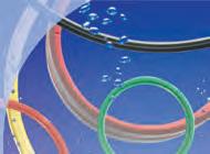
Polyurethane O-Rings Stand the Test of Time
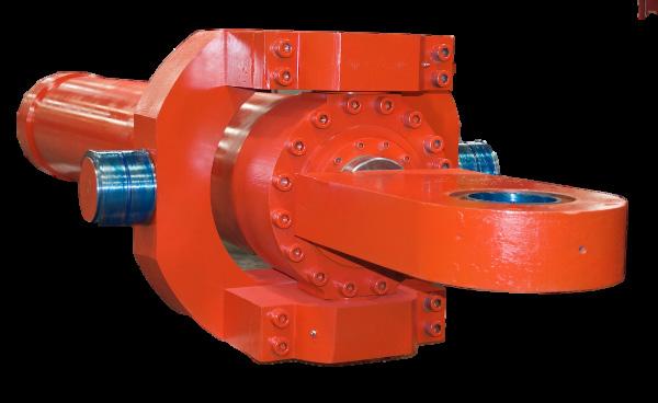
OEMS AND CYLINDER BUILDERS GET A FRESH PERSPECTIVE ON A TRUSTED HYDRAULIC SEAL
By Andrew Iddeson, Product Technology Director, Advanced Sealing Technologies and Grigoriy Cholakov, Head of Technical, Hallite Seals
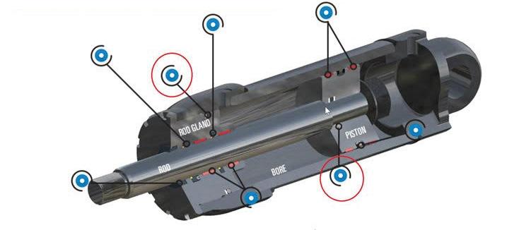
Several new material options, innovations, and emerging technologies have led the fluid power industry, primarily OEMs and cylinder builders, to look closely at polyurethane (PU) O-rings. These common, trusted seals renowned for their durability, resilience, and adaptability have earned their rightful place in hydraulics. Static seals, like PU O-rings, are pivotal in preventing leakage between connecting components in fluid power systems, notably between connecting rods and piston heads, cylinder tubes, and glands. Often considered secondary to dynamic seals, they are instrumental in maintaining pressure where it matters most.
In today's multifaceted fluid power industry, grasping the intricacies of the PU O-Ring, especially in medium and heavy-duty technical applications, is far from straightforward.
Simplified Design
The PU O-Ring replaces the traditional two-piece elastomer O-ring and backup combination, offering a singular, streamlined solution.
This simplification leads to a more straightforward assembly process.
Reduced Assembly Errors
As a single-component solution, the PU O-Ring minimizes the risk of assembly errors that can occur with multi-piece configurations. Ensuring a more reliable and consistent seal performance.
This understanding necessitates advanced manufacturing knowledge, technological expertise, and proven processes for managing the diverse range of material options available. The dynamic nature of fluid power systems demands seals that can perform reliably under varying pressures, temperatures, and operational conditions.
Given these complexities, it is essential to delve deeper into the specific attributes and advantages of PU O-Rings within hydraulic fluid power cylinder applications. We will explore how these seals offer enhanced performance, longevity, and reliability compared to traditional sealing solutions. Additionally, we will examine the manufacturing processes and material characteristics that enable PU O-Rings to meet the rigorous demands of modern hydraulic systems.
Lower Inventory and Handling Costs
Fewer components mean reduced costs related to purchasing and stock handling. Inventory management becomes simpler and more cost-effective.
Compact Solution
The PU O-Ring's compact design is ideal for static applications where space for a seal in the cylinder is limited. This compactness does not compromise its sealing efficiency, making it versatile for various applications.
By reviewing these aspects, we aim to provide a fresh perspective on the application of PU O-Rings. This exploration will not only underscore the technical benefits of PU O-Rings but also emphasize their role in advancing the efficiency and durability of hydraulic systems across various industries. The PU O-Ring is a singular solution that can standardize a cylinder configuration traditionally addressed with different components. It can perform across all duty cycles and a wide range of pressure requirements. The cylinder builder can rely on the PU O-Ring to achieve performance levels of up to 50 MPa (7250 psi) in a singular solution, simplifying the design process. Here are five key advantages of using PU O-Rings in hydraulic cylinder applications:
Versatility in Materials
PU O-Rings are available in a wide range of materials, catering to both low- and highpressure sealing applications.
This versatility ensures that the right material can be chosen based on the specific requirements of the hydraulic system.
Once the design characteristics of PU O-Rings are considered, selecting the appropriate materials for specific applications should not be overlooked. Ensuring the material choice matches the operating conditions is crucial for optimal performance and longevity of the seals.
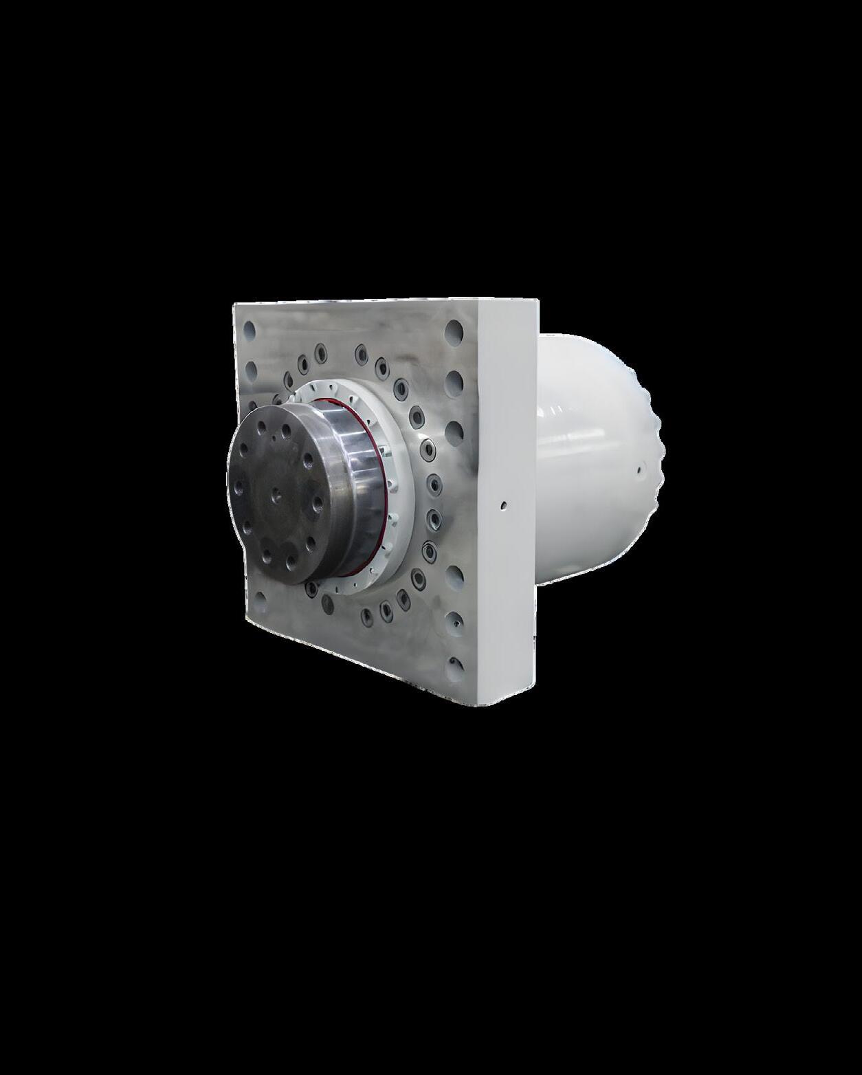
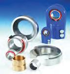
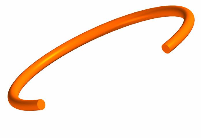
Hydraulic cylinder fitted with Hallite 003 Polyurethane O-Rings
Materials matter
High-performance materials provide desirable assurances, such as easy installation, reliability, and durability. For example, high strength TPU allows the PU O-Ring to withstand high pressure and shock loads. When it comes to materials, there are many options, including the Hythane range, which offers resilience and extrusion resistance and eliminates the need for additional anti-extrusion backup rings. Hythane 591 high-performance polyurethane supports high-pressure sealing, and Hythane 181 is an alternative material option for more demanding low-temperature conditions. Whatever material option you choose should be suited for the application.
Here’s a common situation. An engineer uses a standard O-Ring up to 16 MPa (2320 psi) in NBR 70 in an application. To address the need for a higher pressure in the application, an O-Ring in NBR 90 is added, as an option. However, as the pressure increases further, a backup ring must be added, culminating in three components/options. For every application involving pressure, the engineer must stop and consider a long list of configurations to achieve the desired solution. Since the PU O-Ring as a standard is configured to the highest pressure performance, there is no need for the cumbersome evaluation of pressure and materials for every application. This makes it a safer solution for engineers
who are designing the cylinders, and it saves time.
Equally important is the fact that the PU O-Ring is a single component that saves space in the assembly and storage. Imagine installing hundreds of sizes of O-rings, each requiring an evaluation of configurations and options. We can quickly calculate the number of parts to see how this can become an issue.
Endless potential
As we’ve explored, PU O-Rings have established themselves as an excellent choice for hydraulic cylinder applications. However, their advantages extend beyond this singular use. Various other elements within hydraulic circuits or systems, such as hoses, fittings, and valves, can also benefit from the innovative qualities of PU O-Rings.
The fluid power industry recognizes the challenges associated with fitting valves with O-Rings due to the compact sealing requirements, especially for control and solenoid valves. This is where PU O-Rings demonstrate significant superiority over standard O-Rings, which often require multiple components. PU O-Rings streamline the sealing process, providing a simplified, yet highly effective solution.
The potential applications for PU O-Rings are vast and continuously evolving. Seal manufacturers, in collaboration with industry leaders, are pushing the boundaries to explore new and innovative sealing solutions. This includes applications in emerging sectors such as hydrogen and biofuels, where the demand for reliable and compact seals is paramount.
By leveraging the unique properties of PU O-Rings, the fluid power industry is poised to overcome traditional challenges, opening the door to new possibilities and advancements in hydraulic system design. •
TARGETED DISPLAY ADVERTISING AKA “PROGRAMMATICS”
» THESE DIGITAL ADS help you reach your customers and while increasing your audience reach across all devices. If they’ve been to your website, searched for your products and services, or they’re reading content relevant to what you offer, we’ll help get your message in front of them today!
REACH THE RIGHT CUSTOMERS WITH GEO-TARGETING
» ALL CAMPAIGNS ARE geo-targeted, ensuring that we only share your ad with potential customers in your defined service area. Reach out to people who have attended trade shows and conferences.
3245 Freemansburg Ave, Palmer PA 18045
Phone: 800.730.5904 | 610.923.0380
Fax: 610.923.0390 www.fluidpowerjournal.com
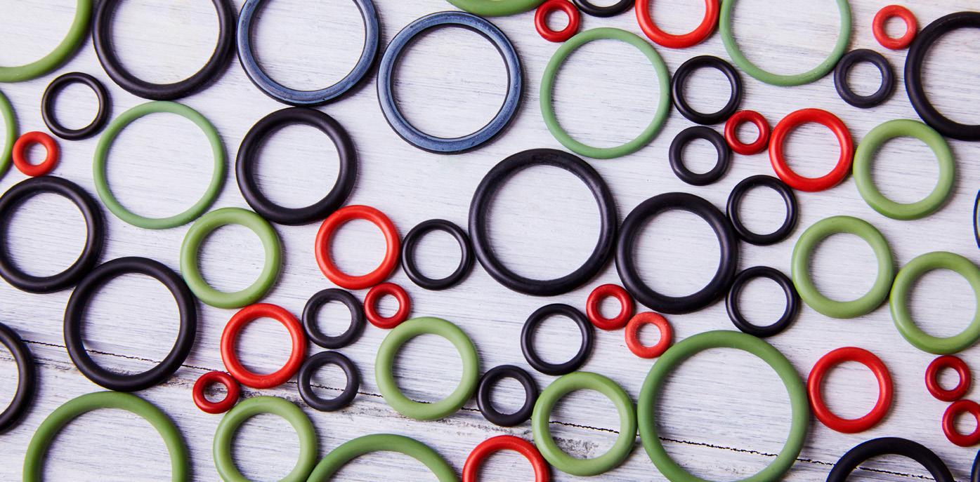
Hallite polyurethane O-Rings in Hythane high-performance materials
The Association For Manufacturing Technology represents U.S. based providers of advanced machinery, devices, and digital equipment critical to the productivity, innovation, and competitiveness of U.S. manufacturing. Headquartered in McLean, Virginia, near the nation's capital, AMT serves as the voice of the industry, fostering innovation, enhancing global competitiveness, and developing the advanced manufacturing workforce of the future. With deep expertise in industry data and intelligence, and comprehensive
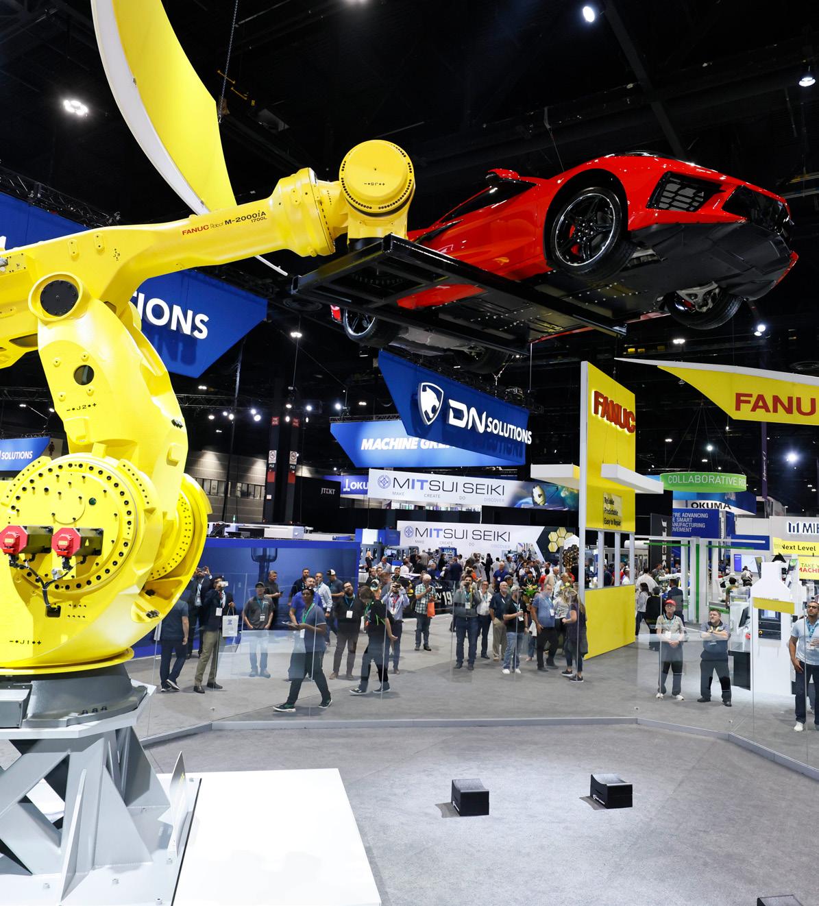
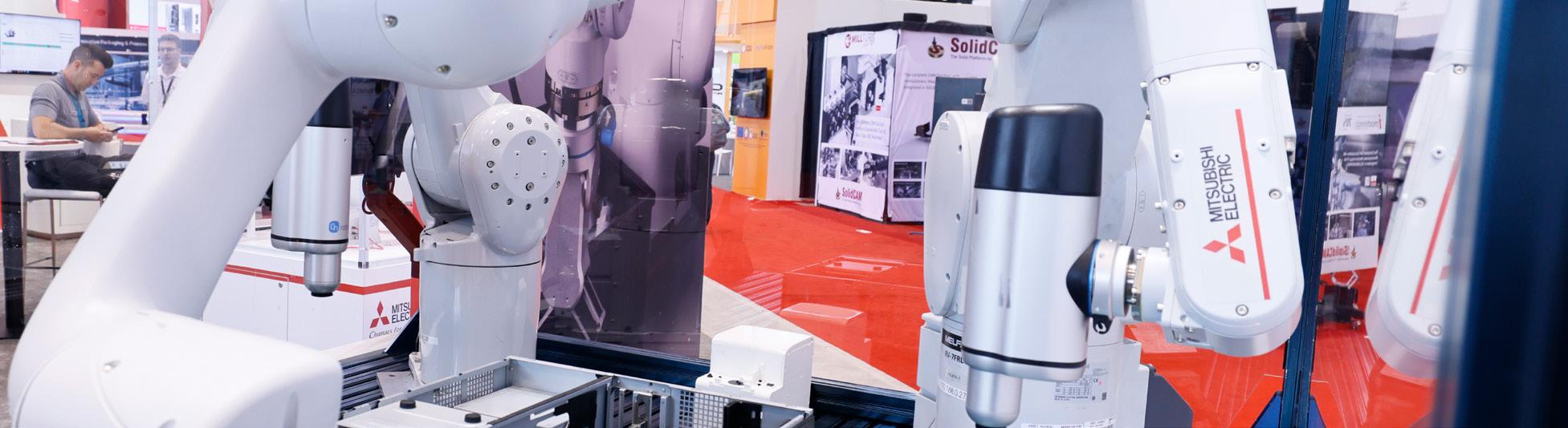
international business operations, AMT provides unparalleled support to its members. A highlight of AMT's activities is the production of IMTS – The International Manufacturing Technology Show, North America's premier manufacturing technology event. IMTS 2024 promises to showcase the latest advancements in manufacturing technology, providing a platform for industry professionals to explore innovations, network with peers, and gain insights into the future of manufacturing. •
IMTS – the International manufacturing technology Show (ImtS.com) is where the creators, builders, sellers, and drivers of manufacturing technology come to connect and be inspired. the show runs from Sept. 9-14 at Chicago’s mcCormick place. Attendees discover advanced manufacturing solutions that include innovations in CNC machining, automation, robotics, additive, software, inspection, and transformative digital technologies that drive our future forward. powered by Amt –the Association For manufacturing technology, ImtS is the largest manufacturing technology show and marketplace in the Western Hemisphere. With more than 1.2 million square feet of exhibit space, the show attracts visitors from more than 110 countries. ImtS 2022 had 86,307 registrants, featured 1,816 exhibiting companies, saw over 7,600 people attend educational events, and included a Student Summit that introduced the next generation to manufacturing.
VISITOR ROLES IN BUYING
Jointly Make a Buying Decision with Others 25% Makes the Final Decision 21%
No Role in Buying Products 20%
1.
Gather Information for Evaluation 16%
Justify the Purchase or Select a Brand 9%
Identify the need for New Products 9% No Response 9%
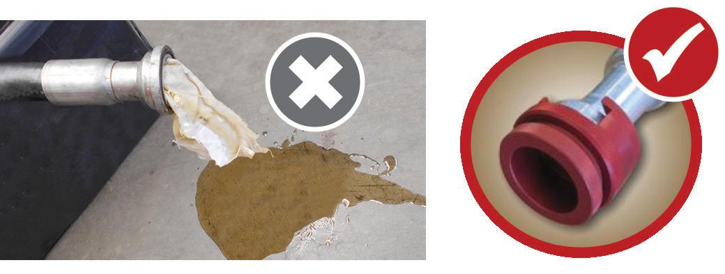
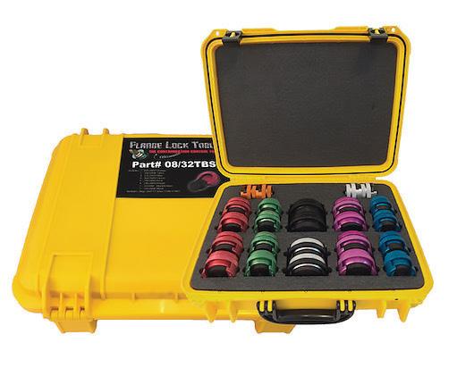
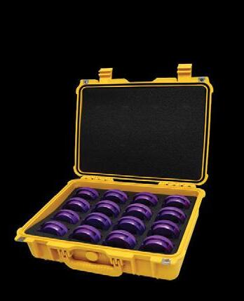
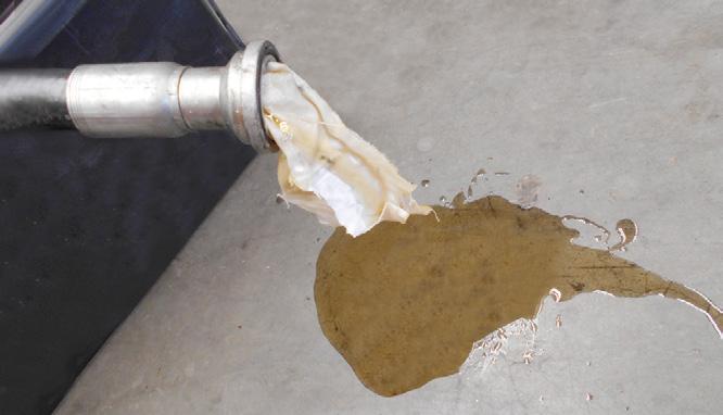
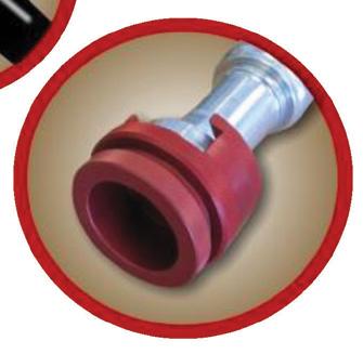
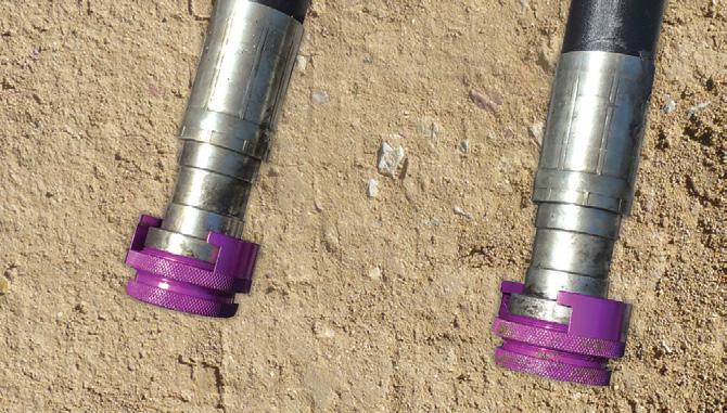
The FlangeLock™ tool and caps are the ultimate contamination control tools for protecting your hydraulic system. The FlangeLock™ allows for the simple sealing of open hydraulic flanges without tools while the caps can be bolted in place of a flange connection. Easy on, easy off, they offer a leak-proof solution to hydraulic systems and environmental cleanliness. FlangeLock™ tools and caps stop the mess.
HITACHI MAKING CONTAMINATION CONTROL EASY
Hitachi have packaged FlangeLock tool and caps specifically for Hitachi mining excavators. The Hitachi customised kits make sure no matter which component routine maintenance is being performed on, you will always have the exact number of FlangeLocks™* and caps to help reduce contamination.
*Note: FlangeLocks™ are not to be used under pressure
The FlangeLock™ Tool is the ultimate contamination control tool for protecting your hydraulic systems. It allows for the simple sealing of open SAE code 61, 62 & CAT-Style hydraulic flanges without tools. Constructed from lightweight aluminum. Easy on, easy off. Offers a leakproof solution to hydraulic system and environmental cleanliness. FlangeLock™ Tools stop the mess!
• No tools
• No expensive hardware
• No more rags stuffed into hoses
• No more messy plastic caps
• The ultimate contamination control tool
•
•
•
National Tube Supply’s fluid power products are precisely manufactured and expertly finished to minimize leakage and ensure longer seal life and optimum performance.
Our experienced team is always available to help customers identify the best product for their project specifications, quality requirements and bottom line. We’ll even work with you to set forecasts for JIT delivery management!
Hydraulic Fluid Line Tubing
Cylinder Barrels
Pneumatic Cylinder Tubing
Pump Barrels
Honed Steel Tubing
Chrome ID Tubing
Chrome OD Tubing
DOM Tubing
Seamless Steel Tubing
Chrome Plated Piston Rods
1045 Steel
Ductile Iron & Alloy
We have a massive inventory at your disposal with 8 locations across North America – most orders ship next day!