Remote production management TSN in real-world manufacturing 23 Factory Automation Connectivity Showcase 36 EtherNet/IP technology & applications update 46 Visit us on the web n www.iebmedia.com ISSN 1470-5745 March/April 2023 Time-Sensitive Networking Technology Update 135 Industrial Ethernet Automation Networking & IIoT Special Report Delivering TSN's benefits to manufacturing Page 15 49 7


�tiiMHA tiii+IIWA C##il+M -GHBHII -£aaQijfii:ii:jii if&Jl◄@M#UMI OPTO 22 4AMiM 4fli+i¥WF Hi##M-M t◄IH: 4H&Mil ihii:: 65iNMN h&:1Hi1'Mii:il:lil OPTO 22 Your Digital Transformation-ready Edge Platform CODESVS i• PAC Control {"ssh --� •' ,..,oov· !:#MANAGE ,..,.,..,..,,1· !:I•� .. VIEW +-+ Node-RED (i) OPENVPN" lgnitionVi ONBOARD _J �tionE□GfViONBOARD _____:__J I Sparkplug �MQTT �UA SERVER Learn more today at www.opto22.com
GET CONNECTED…
TSN and Factory Connectivity
This issue of the Industrial Ethernet Book puts the focus on two key technology areas that are the heart of this publication: TimeSensitive Networking and Factory Connectivity solutions.
Beginning on page 7, we present our annual update on TSN technology along with a series of technical articles on this key technology. This coverage presents a panel of industry experts that provide their perspective on the megatrends and technology shaping the development of Time-Sensitive Networking (TSN) applications. The lure of this technology continues to the convergence of IT-OT applications on a single network especially in tandem with higher-speed, Industrial Ethernet networks.
Three additional TSN articles provide in-depth coverage of this important technology area:
• "How TSN as being applied in real world manufacturing" (page 23)
• "TSN: five ways IEEE standards will advance Industry 4.0" (page 26)
• "TSN preemption for cyclic EtherNet/IP communication" (page 28)
On page 15, we are pleased to present a Special Report on CC Link IE TSN. The addition of Time-Sensitive Networking (TSN) to Industrial Ethernet offers the potential of unprecedented levels of deterministic performance for automation and control applications, along with powerful standards for implementing IT-OT convergence and Industry 4.0 digital transformation.
The Industry 4.0 paradigm is continuing to reshape every industrial sector. The datadriven, automated technologies that this framework leverages are having a vast and lasting impact on every single aspect of manufacturing, from R&D to operations and the entire supply chain.
And finally on page 36, we present our Factory Automation Connectivity Showcase which illustrates the strength and diversity of the Industrial Ethernet ecosystem.

Founded in 1999, inspired by the emergence of Industrial Ethernet as the network backbone for automation and control, the Industrial Ethernet Book is now the only publication worldwide dedicated to automation and machine control networking, and the latest technologies driving digital transformation, the Industrial Internet of Things (IIoT) and Industry 4.0.
Our continuing focus will be to bring our readers the best information available and expert opinions on Industrial Ethernet automation and machine control networking technology and applications.

Al Presher
Industrial Ethernet Book
The next issue of Industrial Ethernet Book will be published in May/June 2023. Deadline for editorial: May 12, 2023 Advertising deadline: May 12, 2023
Editor: Al Presher, editor@iebmedia.com
Advertising: info@iebmedia.com
Tel.: +1 585-598-6627
Free Subscription: iebmedia.com/subscribe
Published by IEB Media Corp., Box 1221, Fairport, NY, 14450 USA ISSN 1470-5745
3 Contents Industry news 4 TSN technology update: 2023 special report 7 TSN Profile Conformance Test Plan 14 Delivering TSN's benefits to manufacturing 15 Converged, high bandwidth manufacturing networks 16 Industry 4.0 challenges and the promise of convergence 17 Ethernet & TSN – switching connectivity up a gear 21 How TSN is being applied in real world manufacturing 23 TSN: five ways IEEE standards will advance Industry 4.0 26 TSN preemption for cyclic EtherNet/IP communication 28 2023 factory automation connectivity showcase 36 EtherNet/IP technology and applications update 46 Switches enable IT-OT convergence 48 Remote production management: anytime, anywhere. 49 EtherCAT measurement terminals for wind farm monitoring 52 Vision-guided robots: cameras give robots human-like functions 54 Energy management and demand monitoring generates savings 56 High-channel density digital I/O modules for factory automation 59 New Products 63
03.2023 industrial ethernet book Contents
Visit our new website at: www.iebmedia.com
Factory Connectivity Showcase: 36
New Products: 63
Digital Twin Consortium and OPC announce liaison agreement

Agreement to advance the use of digital twins in manufacturing across industries. The collaboration is expected to influence interoperability standards and processes by harmonizing technology components.
Digital Twin Consortium (DTC) and OPC Foundation has announced a liaison agreement to accelerate the development and adoption of digital twin-enabling technologies. The DTC and the OPC Foundation have worked closely in several open-source reference implementation projects on GitHub and have agreed to collaborate even closer.
“We are excited about working with OPC Foundation,” said Dan Isaacs, GM, and CTO of DTC. "Through our collaboration, we will influence interoperability standards and processes that will advance the use of digital twins in manufacturing across many industries.”
The DTC and OPC Foundation have agreed to the following activities:
• Collaborating on standardization requirements
• Realizing interoperability by harmonizing technology components and other elements
• Aligning work in horizontal domains for adoption in vertical domains and use cases, proof of concepts, and Value Innovation Platforms (VIP) programs including: Technology, terminology, and taxonomy; Security and trustworthiness; Conceptual, informational, structural, and behavioral models; Enabling newer technologies such as simulation and AI; Technology stack across the digital twin lifecycle; and Case study development.
• Developing and understanding opensource reference implementations
Stefan Hoppe, President OPC Foundation, said, “The OPC Foundation maintains the global standard for secure industrial interoperability for information modeling and data exchange, which, as part of this relationship with DTC, benefits all who wish to create semantically identical digital twins. Our involvement to liaise with DTC further strengthens the user’s ability to model each data aspect quickly and precisely, creating and interacting with any digital twin. Digital twins will be fully compatible with the OPC UA framework used in the run-time components within the operational domain.”
“As one of the key contributors to Digital Twin Consortium’s open-source program, Microsoft saw the rising demand for open digital twin technology and industrial interoperability standards like OPC UA. The collaboration of OPC Foundation and DTC
OPC Foundation Welcomes Procter & Gamble as its 900th Member
The OPC Foundation is proud to welcome Procter & Gamble as the 900th OPC Foundation member. A leading consumer goods company, P&G is also a global leader in the Smart Manufacturing domain through its efforts to drive innovation by using digital technologies, including OPC Unified Architecture (OPC UA), in a concept they call “constructive disruption.”
Procter & Gamble’s Manufacturing Operations have been recognized in delivering industry leading performance and capability over many years made possible by leveraging their operational excellence program called Integrated Work System (IWS). Based on this success, IWS is not only leveraged across their 100+ manufacturing sites globally, but now also 450+ non-compete manufacturing operations are leveraging IWS to deliver superior results. Procter & Gamble is taking this to the next level by bringing artificial intelligence and machine learning to their processing equipment in ways that continue to advance their heritage of operational excellence across the smart manufacturing spectrum.
P&G is shaping its future by leveraging open standards in the industrial ecosystem in order to deploy their technologies at scale. OPC UA is an integral part of the industrial communication framework within P&G’s automation systems, providing secure connectivity from sensor to cloud.
When asked about P&G’s efforts to harmonize their digital transformation while advancing their heritage of operational excellence, Jeff Kent, Vice President, Smart Platforms Technology & Innovation, P&G, stated: “It is critically important to P&G to have an innovation and operational ecosystem that can enable the speed-to-value-creation and sustained operational excellence expected from smart manufacturing."
will continue to elevate the impact of digital twin technologies. These two organizations have already started collaborating on opensource projects and these projects will expand to include emerging technologies,” said Erich Barnstedt, Chief Architect Standards, Consortia and Industrial IoT, Azure Edge + Platform, Microsoft Corporation.
Both consortia will exchange information through regular consultations, joint contributor relations, seminars, open-source projects, and other activities.
News report by DTC and OPC Foundation.
Visit Website
ethernet book 03.2023
4 Industry news industrial
SOURCE: DIGITAL TWIN CONSORTIUM
View video to learn more about the Digital Twin Consortium. https://www.youtube.com/ watch?v=yIzN4yHIBwo
Vision: Complete and system-integrated

industry-standard, real-time image processing solution complete with integrated software and hardware full synchronization with all EtherCAT-based machine processes reduced wiring work thanks to the EtherCAT P single-cable solution cameras with 2.5 Gbit/s for rapid image transfer
C-mount lenses with assembly-oriented design future-proof lenses designed with 2 µm pixel structure correction of chromatic aberration into the near-infrared range wide range of EtherCAT-compatible, precisely synchronizable, multicolor LED illumination options maximum flexibility afforded by image contrast adjustment during runtime and high pulse power Vision Unit Illuminated is a compact unit comprising of a camera, illumination, and focusable optics

Scan to learn more about Beckhoff Vision
VI11-01E |
Hall 9, Booth F06
EV-RPG2
Complete Industrial Ethernet Communication
Interface Reference Design Supports Multiprotocol

Requirements
X Proven and verified hardware and software system design saves development time and risk.
X Precertified multiprotocol software for Ethernet/IP, EtherCAT, Modbus TCP/IP, and PROFINET.
Learn more at analog.com/EV-RPG2.
TSN Technology Update: 2023 Special Report
Industry experts provide their perspective on the megatrends and technology shaping the development of Time-Sensitive Networking (TSN) applications. The lure of the technology continues to the convergence of IT-OT applications on a single network especially in tandem with high-speed, Industrial Ethernet networks.
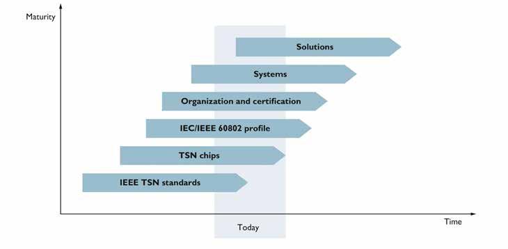
“The enabling of TSN requires Ethernet hardware and software that supports the necessary IEEE standards. We can see that many chip manufacturers are integrating TSN capabilities into new and already existing devices,” Lessmann said. “These new building blocks still need to be integrated into new versions of automation products by device manufacturers and finally tested and certified before they can be used in OEM automation Solutions.” -- Gunnar Lessmann, Master Specialist Profinet and TSN, Phoenix Contact.
TIME-SENSITIVE NETWORKING CONTINUES
to move forward offering the elegance and simplicity of a single network, solutions for IT-OT convergence and the fulfillment of IEEE/ IEC 60802, backed by the collaboration efforts of a wide range of industrial companies.
In this special report, the Industrial Ethernet Book reached out to industry experts to gain their insights into the technology megatrends driving Time-Sensitive Networking, the possibilities of new applications and the challenges for automation engineers.
Evolving TSN Landscape
Key automation building blocks and software integration needed.
According to Gunnar Lessmann, Master Specialist Profinet and TSN for Phoenix Contact, the continuing emergence of TSN will require industry developments at many levels.
“The enabling of TSN requires Ethernet hardware and software that supports the
necessary IEEE standards. We can see that many chip manufacturers are integrating TSN capabilities into new and already existing devices,” Lessmann said. “These new building blocks still need to be integrated into new versions of automation products by device manufacturers and finally tested and certified before they can be used in OEM automation Solutions.”
He said that, in addition, the "industrial middlewares" such as PROFINET or OPC UA need to support TSN. Based on this model, in 2023 each middleware has its own "roadmap" regarding TSN.
“Each point of these is complex and represents a challenge for large scale market adoption. But all items are addressed and under work in the responsible organizations,” he said.
TSN technology focus
When asked about what specific application areas or markets are a fit for TSN, Lessmann responded that a specific application or
market for TSN cannot be identified. Basically, all applications are candidates for TSN that benefit from high determinism and bandwidth, short cycle times, synchronization, and IT/ OT convergence in a single network. This goes from industrial image-recognition and processing over motion-control to energy management in substations.
Thanks to IEEE-standardization of TSN, all these applications can be solved with the same hardware and may differ only in software support. But it still offers significant potential benefits for smart manufacturing.
“The biggest advantage of TSN is the so-called convergence of IT and OT applications in just one network. This is especially valid in combination with link-speeds of 1Gbit/s or more,” Lessmann said.
“TSN allows the combination of functions from classic high-deterministic fieldbus systems and IT applications like large data transfer in one network. Today separate networks for IT and OT are used in many applications leading to higher device and
7
TSN Technology 03.2023 industrial ethernet book
SOURCE: PHOENIX CONTACT
“We expect that systems of this kind will become more prevalent due to industrial IoT and edge computing trends. TSN will then act as an 'ITOT software-defined network infrastructure' and interaction with the network configuration management services will be handled by application layer services such as OPC UA FX, DDS, and Kubernetes,” -- Georg Stöger, Director Training & Consulting and Alexander Damisch, Vice President Dependable Networks, TTTech industrial.
installation costs, know-how, etc.,” he added.
As far as the expected impact of TSN, Lessmann offered a different perspective.
“Let me explain this with an example from industrial image processing. A synchronized Ethernet camera captures images during the running process. The image data is transported deterministically to a controller and processed in real time. Then, depending on the result, actuators such as valves or drives are controlled, which act synchronously on the running process. In addition, the actuators and the camera provide further information about themselves and other process parameters that enable predictive maintenance in the “cloud,” Lessmann said. “With TSN, all this is possible in one network with just one planning, installation and operational support. Furthermore, classical digital process-sensors may be reduced. The configuration can also be changed during operation without influence on other devices. TSN in applications such as these enable significantly higher flexibility,” he concluded.
TSN Technology Advances
Focus on industry collaboration, QoS Ethernet and TSN-enabled applications.
Georg Stöger, Director Training & Consulting at TTTech Industrial along with Alexander Damisch, Vice President Dependable Networks for TTTech, together responded to our questions about continuing developments with Time-Sensitive Networking.
Their viewpoint is that, although TSN has still not been widely adopted in automation products currently available on the market, three very significant advances are enabling further and faster adoption. Here is a summary of those advances.

#1 - An industry-wide collaboration group (TIACC, https://www.tiacc.net/ ) for ensuring conformance of industrial TSN components according to the IEC/IEEE 60802 profile has been established. Industrial networking consortia that have announced the adoption of TSN – including OPC UA FLC, PROFINET, CC-Link, ODVA – are joining forces with the Avnu Alliance to define a common conformance test plan for TSN capabilities.
This will ensure that industrial TSN networking components will work seamlessly together, both in applications where TSN is used as a high-performance extension for the existing industrial networking technologies and in more integrated, converged architectures where several previously competing industrial networking technologies co-exist.
#2 - TSN is increasingly established not just as QoS improvement for Ethernet, but as base technology for a dependable communication sublayer for application layer technologies, including OPC UA, the Open Communication Framework (OCF) of the Open Process Automation Specification (OPA-S), and DDS.
#3 - As vertical market-specific profiles and TSN enabled hardware become state of practice, a more software-defined world is emerging, where software stacks and tools to support deployment of TSN enabled applications and products are being developed.
Stöger and Damisch added that there are several “philosophies” on how to apply TSN to industrial applications.
The conventional “system builder” approach results in a fully engineered network, and TSN is a great fit for this kind of approach because it provides mechanisms to statically configure a multitude of networking services and robust delivery.
• The “plug and produce” approach adds a dynamic element of run-time reconfiguration to the mix, but still requires that the network performs deterministically like an engineered OT network after each reconfiguration. Again, TSN is a great fit for this use case.
• For IT-centric (non real-time) applications, which are probably managed with containerization and orchestration and operate as webservices, TSN supports the flexibility and performance of QoS Ethernet.
• The unique application area for TSN is when all these paradigms need to be combined, i.e. when a system contains statically configured, robustly isolated networking functions for OT applications, but also requires dynamic, flexible reconfiguration and adaptation during runtime to support “plug and produce” as well as edge computing and connectivity to the cloud with containerized, orchestrated web services.
“We expect that systems of this kind will become more prevalent due to industrial IoT and edge computing trends. TSN will then act as 'IT-OT software-defined network
8 industrial ethernet book 03.2023 TSN Technology
SOURCE: ISTOCKPHOTO
infrastructure'; interaction with the network configuration management services will be handled by application layer services such as OPC UA FX, DDS, and Kubernetes,” they added.
When asked about specific application benefits that TSN provides, they offer three specific areas:
Higher, faster, further
Probably the least surprising benefits of TSN versus classic fieldbus technologies based on 10/100 Mbit/s Ethernet are the incremental performance gains that the technologies in the “TSN toolbox” can provide for automation applications – higher communication bandwidth, lower communication latency. This is mainly relevant where existing applications could not be scaled because of technical limitations.
Wired-wireless network architectures with unified management
The tighter integration of TSN with 5G wireless networking technologies and layer 3 enhancements (IETF DETNET) to provide consistent networking quality of service (QoS) and synchronization services across a complex automation plant/system with wired and wireless domains.
Communication services with defined QoS for applications distributed across several such domains can be established and managed without having to configure and manage the individual network controllers separately. Dynamic network reconfiguration, which would otherwise be very complex and possibly
subject to vendor-specific tools, will become a standard service.
Industrial edge computing architectures
The co-existence of OT applications (IEC 61131, 61499) with reliable real-time communication requirements, IT/cloud applications and networking protocols in a converged infrastructure is becoming reality. This means virtualized and containerized applications will be managed more and more by agile delivery of services and applications. While the app is becoming software-defined, making sure applications can be developed independently of their physical deployment, software-defined networks (SDN) are needed to ensure the Quality of Service (QoS) of the production and consumption of the data the applications need. These highly configurable QoS and determinism needs from the network are all key capabilities provided and guaranteed by TSN.
As far as the expected impact that TSN technology will have on smart manufacturing, and the general timeline for these innovations, they concluded that, as noted above, we expect that TSN facilitates integrated IT-OT edge computing architectures, also for smart manufacturing.
“As a technology provider, we cannot speak to the specific impact and timelines that our customers envision for their manufacturing systems, but for companies who want to influence the standards and reference architectures, now is the time to get involved.”
Convergence and Unification
Different types of traffic on a single network.
Thomas Burke, Global Strategic Advisor for the CC Link Partner Association, said that Time-Sensitive Networking technology is moving ahead with sweeping changes that are impacting automation and machine control networking.

“The industrial communications landscape has dramatically changed over the years. I remember when Ethernet was first coming into the factory, and it took a while to be successfully understood that this was the right technology for factory and process automation,” Burke told IEB.
“The value of TSN is it's clearly about the convergence of networks and the ability to have multiple industrial Ethernet networks running on the same physical wire. But what customers are realizing with the value of the technology is the fact that they can perform control applications simultaneously and be able to configuration applications – plus they can have other applications and devices like printers and cameras on the same wire without affecting control."
Burke said that things like safety and motion are commonplace on industrial Ethernet networks and the fact that it will be able to add new devices to the network while the network is being used for control applications will make the life of everyone much easier. There are a multitude of opportunities that can leverage the deterministic performance and the ability to address digital transformation
9
03.2023 industrial ethernet book
SOURCE: CLPA TSN Technology
“The value of TSN is it's clearly about the convergence of networks and the ability to have multiple industrial Ethernet networks running on the same physical wire. But what customers are realizing with the value of the technology is the fact that they can perform control applications simultaneously and be able to configuration applications." -- Thomas Burke, Global Strategic Advisor, CC Link Partner Association.
and IT to OT conversions that TSN technology provides. Safety and security are critical components that automation applications clearly need.
TIACC Collaboration
Industrial Ethernet organizations are working closely together and have formed a partnership to validate the technology known as TIACC (TSN Industrial Automation Conformance Collaboration).
“The challenges of adoption are the concerns of the manufacturing community as to how they support all these legacy devices that are currently running on their own different industrial Ethernet networks,” Burke said. “Clearly, we will need the necessary bridges and gateways and switches that will enable the existing devices and networks to coexist with this great new TSN technology.”
He added that the beauty of the TSN technology is that there is no application area or market that cannot benefit from this transformative technology.
“TSN truly is a game-changing technology because it allows high speed performance deterministic operation and supports convergence of the different industrial Ethernet networks coexisting on the same physical wire,” he said. “But if you think about markets specifically that are recognizing the benefits, you will see that automotive, pharmaceutical, oil and gas, water treatment, food and beverage, and the semiconductor industry all will benefit with dramatic increases in the capability and the beauty of being able to support complex applications in this new digital transformation. We will now be able to have data analyzed from many disparate devices and disparate networks and convert it into useful information for the IT world -- and all existing on the same physical wire.”
He said that one area that will see a significant benefit in the one-wire concept is robotic applications. Robotics has been preaching single-payer Ethernet for a long period of time and coupled with power over the data line and TSN technology, nothing won't be able to be accomplished. But he added that the technology also really supports the concept of quality of service. This is a significant value to TSN technology and will allow support for existing devices coexisting. Although, it will not have the same benefits of the quality of service that you have in a TSN network.
“Determinism has always been a benefit of the existing industrial Ethernet networks, but now with TSN it takes it to the next level. IEC/ IEEE 60802 is an evolving standard where the focus is changing the world in comparison to standard unminified Ethernet,” he said.
His view is that there are so many technical benefits and technology changes that should be easily adopted by suppliers rolling out
TSN products. Typically, networks have been underutilized but now with the new volume of devices, people are starting to realize they need connectivity and higher speed networks, which will give us the capability of better utilization and performance along with the coexistence of multiple networks running on the same wire. Clearly, we can have universal quality of service and fault tolerance now being built into the industrial Ethernet protocol when leveraging TSN technology.
TSN application benefits
Burke said that TSN’s specific application benefits are clearly that the automation industry -- both process and discrete -- really wants complete solutions from top to bottom and to be able to have IT and OT applications share data and information in a bidirectional fashion.
“The fact that there is a push for this whole new digital transformation and making use of complex information data models is driving the adoption and need for TSN technology,” he said. “There's a lot more data and information that can be leveraged with this new strategy and specifically how you can have ‘plug and play’ when adding new devices on a network without affecting the existing control applications running simultaneously.”
A driving force is that there are a multitude of vendors that are building TSN technology on a chip, which will really facilitate adoption of the technology. So, the business value is clear that there is significant value in the increased determinism and performance on this new converged technology and it's driving new vendors to look for opportunities to become the toolkit vendors to really help companies adopt the technology.
“The standardization of TSN and the standardization of these different data models really brings the digital transformation to reality. There have been a multitude of information model organizations that all were
operating independently and you're going to start seeing the ability to have all of these different devices and applications leveraging these standardized information models because of the increased network bandwidth of the TSN technology,” Burke said.
The industrial Internet organizations are rapidly working to develop their corresponding industry standards to embrace TSN technology. CLPA released CC-LINK IE TSN in November of 2018 officially. The significance of this was they recognized that the technology of TSN was evolving but they could still put a stake in the ground to help the end users through the development of products by suppliers to achieve and begin their journey in support of smart manufacturing.
TSN developments
Burke said that recently a number of the other industrial Ethernet organizations have been rolling out their TSN-based standards to help their suppliers bring TSN products to market. Success is measured by the level of adoption of technology and clearly there are a multitude of vendors that are actively developed or have already released products supporting the TSN technology in their products.
“The industry is ready for the technology, but it takes time for the major automation players to roll out a complete portfolio of their products supporting this brand-new technology. Some of the automation players, like Mitsubishi Electric Automation, have already rolled out all of their products supporting TSN technology. Mitsubishi Electric Automation also recognizes the need to have all of the industrial Ethernet networks supported with their product portfolio, as well as a number of the other major automation suppliers all support multiple industrial Ethernet protocols from a connectivity solution with their products either natively or through third-party products that provide the gateways to other networks,” he said.
10 industrial ethernet book 03.2023 TSN Technology
SOURCE: CLPA
Industrial Internet organizations are rapidly working to develop their corresponding industry standards to embrace TSN technology. CLPA released CC-LINK IE TSN in November of 2018 officially.
“So, the simple answer is it takes a while to have native adoption of these important evolving industry standards but in the meantime there's the ability to have connectivity and leverage TSN technology through interim product solutions. We will always have a multitude of process and discrete operations that will have an existing system of different devices and networks that will need to be bridged into this new technology. Many manufacturers are developing products that will allow this new TSN technology to coexist with all of the legacy devices and networks already installed,” he added.
Not a Comprehensive Solution
Biggest benefit of TSN is level above real-time control, for synchronization of network controllers.
Martin Rostan, Executive Director for the EtherCAT Technology Group, told IEB that TSN technology advances have been slower than many anticipated, and its strengths are not at the real-time control level but instead the level above the controller.
"We continue to hope that TSN technologies will be suitable to cost-effectively realize vendor-independent real-time features at the controller-to-controller communication level and above,” Rostan told IEB recently. Costeffective in that TSN technologies will become commodity and supported by all commercially available Ethernet switches and chips - not just dedicated devices and chips for the automation industry. Vendor-independent in that common approaches to configuration are becoming prevalent.”
He added, however, that development
continues to be delayed, and it is already clear that TSN technologies are unlikely to live up to expectations.
“Contrary to what was expected years ago, TSN is not gaining acceptance in general IT applications, and there is unlikely to be a general approach for heterogeneous automation networks that is independent of manufacturers and fieldbus technologies. This means that TSN will establish itself in some isolated solutions, but will not become the comprehensive solution that many are hoping for,” Rostan said.
According to Rostan, at this point it must be said again that there is no such thing as "the TSN" or "the TSN technology". He added that the TSN Task Group of the IEEE is working in more than 40 projects on a variety of technologies, not on one.
“I like to compare TSN with a large selection of spices, which are delivered without a recipe: IEEE doesn't even claim to specify how the technologies should be used. And it is now up to the cook what he makes of it,” Rostan said. “One uses only a few selected spices, the other prefers others, or many more. And so the dishes that are created with the same set of spices differ massively. And just as a dish is not just spices, TSN is not a communication solution or industrial Ethernet system.”

He said that Time-Sensitive Networking can be used by such systems to improve their availability or their real-time properties. Even the joint "60802 working group" of IEC and IEEE, which deals with the application of TSN technologies for the automation industry, does not have the goal of creating the TSN cooking recipe and thus interoperability - here it is "only" about co-existence of many different "TSN recipes". Therefore, the question of
"unique solutions" is correct; there will be several TSN recipes that are incompatible with each other, which in the best case can co-exist on the same network.
“The idea is to use TSN technologies to improve the real-time properties of communication between controllers, while at the same time providing bandwidth for non-real-time communication,” Rostan said. “No market-ready solution is yet within reach, and it remains to be seen what it will look like - and how complex the configuration will be, and what it will cost. And unfortunately, the solution will probably not be vendorindependent.”
Rostan concluded by stating that real-time communication has the greatest impact on smart manufacturing at the level below the controller: i.e., in the communication from the controller to its sensors and actuators.
His view is that TSN-based approaches will not have any advantages over the much simpler and more powerful EtherCAT Device Protocol.
“At the level above the controller, where TSN technologies belong, we hope for better synchronization of networked controllers. This will probably be possible in a few years, but I don't expect it to become widespread: the applications that will significantly benefit from it are not numerous enough,” he said.
IEEE/IEC 60802
Different types of traffic on a single network.
According to Dr. Al Beydoun, President and Executive Director at ODVA, TSN is enabling technology in the development of advanced automation application solutions in 2023 although he see challenges to large scale adoption.
“IEEE/IEC 60802 Time Sensitive Networking (TSN) will make it possible to have different types of traffic running on a single network with priority applied to each message that will ensure that the most critical information arrives on time, such as safety packets, with other less important information, like routine diagnostics, arriving with a delay, if needed,” Beydoun told IEB recently.
“This also opens up the door for multiple communication protocols to run on a single network with fair quality of service, depending on the message type and priority. The ability to include many different types of devices, such as machine vision, surveillance cameras, safety light curtains, and more, on the same network will simplify planning and make it easier for data to flow from the plant floor to the controller, edge, and the cloud. 60802 TSN will also enable additional devices to be added to machines after initial commissioning without degrading network performance or impacting existing devices."
11
SOURCE: RAWPIXEL TSN Technology 03.2023 industrial ethernet book
“I like to compare TSN with a large selection of spices, which are delivered without a recipe. IEEE doesn't even claim to specify how the technologies should be used. And it is now up to the cook what he makes of it. And just as a dish is not just spices, TSN is not a communication solution or industrial Ethernet system.”-- Martin Rostan, Executive Director, EtherCAT Technology Group.
Beydoun said that challenges related to large scale adoption of 60802 TSN include development of the prioritization mechanisms that will need to be configured within switches across the broader network to ensure appropriate quality of service is applied to each packet during transportation.
“Without software configuration tools that allow for centralized commissioning diagnostics, and configuring network changes for all different types of traffic regardless of protocol, device type, or vendor, the value of TSN is significantly reduced and other solutions, such as simply increasing the overall bandwidth, become more practical,” he said.
Additionally, since the IEC/IEEE 60802 TSN specification hasn’t been finalized yet, there are risks to installing TSN devices too early in case there turn out to be interoperability issues with devices that don’t adhere to the final specification.
TSN application solutions
Artificial Intelligence (AI) neural networks and Machine Learning (ML) algorithms that rely upon camera images and training models to identify quality defects compared to the desired output are a potential use case for TSN. Over time, higher resolution images, additional camera angles, or an increased number of images could be transported over
the network to help the algorithm improve quality with additional input.
Beydoun said that TSN would ensure that the critical information on the network would be able to continue to arrive when needed despite any increases in the amount of data relative to total bandwidth. Another possible use case is the transport of different communication protocols through the network to a consolidated edge device for upload to the cloud. While this data wouldn’t be used for control, it would be important to ensure that it didn’t interrupt other critical control traffic on the network.
“Network performance issues can be ameliorated today, for example, by increasing the total bandwidth or by identifying the root cause of the traffic bottlenecks and working to remove them via network segmentation or the addition of network switches to filter unnecessary traffic,” he added.
Properly configured 60802 TSN networks would be able to simply prioritize the most important safety and I/O traffic while allowing other diagnostic and non-time critical packets to wait until the pipeline is freed up. One of the advantages of 60802 TSN is that you can take a network that would have otherwise had an unacceptable amount of jitter, latency, and lost packets due to peak traffic exceeding the available bandwidth and transform it to
a reliable network by prioritizing critical messages and having lower priority messages wait until traffic clears up.
Looking ahead
Beydoun said that 60802 TSN will make it easier to host converged networks with different communication traffic types, and potentially even protocols, assuring a high degree of availability for critical messages resulting in dependable network performance. Additionally, 60802 TSN networks will have the advantage of being capable of accepting additional devices on the network in the future with known impacts on performance. 60802 TSN will also help prepare for future solutions, such as AI, that can bring valuable new approaches to the table that can optimize production, but could also add additional data transportation requirements over time to existing networks.
“Once the IEC/IEEE 60802 standard is published, ODVA will finalize and publish a Common Industrial Profile (CIP) Application Profile to make 60802-enabled TSN an option for new EtherNet/IP devices either natively or via a gateway. EtherNet/IP is anticipated to have an 60802 TSN compatible specification available as soon as is practical after the IEC/ IEEE 60802 TSN specification is released,” he stated.
12 industrial ethernet book 03.2023
SOURCE: ISTOCK TSN Technology
“IEEE/IEC 60802 Time Sensitive Networking (TSN) will make it possible to have different types of traffic running on a single network with priority applied to each message that will ensure that the most critical information arrives on time, such as safety packets, with other less important information, like routine diagnostics, arriving with a delay, if needed.” -- Dr. Al Beydoun, President and Executive Director, ODVA.
TSN Profile for Industrial Automation
Large-scale adoption may be linked to working group’s conclusions.
“The Institute of Electrical and Electronics Engineers (IEEE) finished the basic standardization of TSN some time ago.” Phil Marshall, Chief Operating Officer at Hilscher North America told IEB recently.
“However, it consists of a set of standards that cover a range of real-time requirements across a diverse array of markets including automotive, medical and industrial. This makes it necessary to agree upon a base set of parameters and definitions for how TSN should
be utilized by each industry,” Marshall said.
He added that an International Electrotechnical Commission (IEC) 60802 working group has taken over this responsibility and has been tasked with determining a “TSN Profile” for industrial automation. Their latest draft, version 1.4, was released in July 2022 with ongoing discussions continuing.
“We will have to wait and see how largescale adoption plays out based on this working group’s conclusions,” Marshall said.
Looking at TSN applications
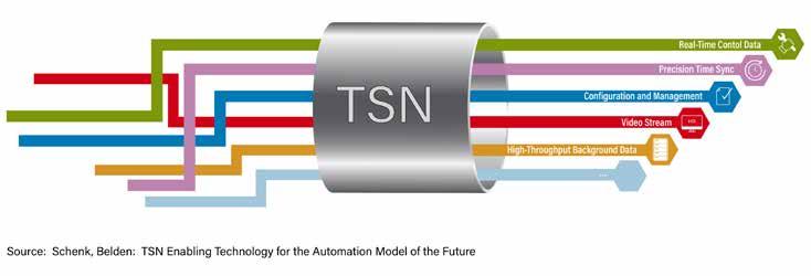
According to Marshall, TSN is a rule-set that decides how traffic transmits through Ethernet networks in a deterministic way. It also
minimizes jitter. Its intention is no different from any existing standards. As an IEEE standard, it is not driven by individual firms and therefore has the potential to harmonize layers two and three of the Open Systems Interconnection (OSI) model in industrial communications.
This standard also has unlimited media compatibility, allowing TSN to use Single Pair Ethernet (SPE) or even 5G for data transmission. TSN transport mechanisms are pictured in the graphic above.
“TSN’s time synchronization and real-time mechanisms allow designers to cluster controls based on Gigabit Ethernet, which enables more complex automation systems. For applications in general, both accuracy and control complexity will increase,” Marshall said.
“Depending on how the standardization evolves, it may become feasible to connect different machines from different vendors. In terms of network topologies, another possible benefit is to combine the OPC UA PublishSubscribe mechanism with TSN to facilitate a common data model between the field and the cloud,” he added.
His assessment is that TSN is a technology with huge potential because it will enable more complex control and massively extend the capacity to address current industry challenges in asset management, remote monitoring and diagnostics, edge computing and cloud-based architectures as well as applications. However, market assessments widely differ in their predictions of business and adoption times.
Hilscher expects to see a wider usage of TSN-based controls and devices from 2025 onwards.
“As an industrial automation “enabler” company, we are following developments closely. TSN-based equipment for 100-Mbit applications is already available today, and our future generations of Gigabit devices will unlock the full potential of TSN whenever the market demands it,” Marshall added.
Al Presher, Editor, Industrial Ethernet Book
13 03.2023 industrial ethernet book
TSN Technology
“Depending on how the standardization evolves, it may become feasible to connect different machines from different vendors. In terms of network topologies, another possible benefit is to combine the OPC UA Publish-Subscribe mechanism with TSN to facilitate a common data model between the field and the cloud.”-- Phil Marshall, Chief Operating Officer, Hilscher North America.
SOURCE: ISTOCK
SOURCE: HILSCHER
TSN Profile Conformance Test Plan
Single common conformance test plan for IEC/IEEE 60802 TSN Profile for industrial automation.
IN MAY 2022, THE AVNU ALLIANCE, CC-LINK Partner Association, ODVA, OPC Foundation, and PROFIBUS & PROFINET International jointly announced that they are collaborating to develop a single conformance test plan for the IEEE/IEC 60802 Time Sensitive Networking (TSN) profile for Industrial Automation.
This collaboration continues to be important to the development of TSN standards.
Testing the TSN Profile for industrial automation
The test plan will be used as a base test by all the participating organizations and made available to the broader Industrial Automation ecosystem. This collaboration contributes towards end user confidence that 60802 conformant devices from different manufacturers which support different automation protocols will coexist reliably at the TSN level on shared networks, including with devices using TSN for applications other than automation.
The focus of the collaboration is to work together towards a jointly agreed and owned test plan for the industrial automation market. This formal collaboration provides value by creating a structure in which all these organizations can work together and exchange ideas towards the end goal of interoperability and coexistence on open, standard networks for all protocols, without needing to
establish a separate, formal organization. For convenience, the collaboration activities will be referred to as “TIACC” (TSN Industrial Automation Conformance Collaboration).
Commitment to interoperable ecosystem
The TIACC marks a commitment by these organizations to develop an interoperable ecosystem of devices from different manufacturers to comply with the IEC/IEEE Standards Association 60802 profile and enable end-users to confidently deploy these devices on open, standard networks. The goal is to have the final version of the single, shared test plan available soon after the IEC/ IEEE 60802 profile is published.
“Avnu’s purpose and mission is to transform standard networks to enable support for many time sensitive applications and protocols in an open, interoperable manner. This collaboration among organizations will be critically important to facilitating coexistence of multiple workloads and protocols according to IEEE 60802 on a network, while leveraging foundational network interoperability that is used across industries,” said Greg Schlechter, Avnu Alliance President. “We are committed to working with the industries to enable an interoperable ecosystem of devices that allow end users to confidently deploy on open, standard, and converged networks.”
Time-Sensitive Networking (TSN) Test Tool Program
Avnu Alliance has announced the expansion of its time-sensitive networking (TSN) Test Tool program by opening the test tool ecosystem to new vendors. As part of this expansion, 3rd party vendor test tools can be verified and validated through Avnu’s rigorous process, which is designed and maintained by experienced certification management professionals and TSN subject matter experts to ensure that it meets the interoperability standards of Avnu’s Global Certification Program.
“Adding new test tools, such as Keysight’s TSN Test Tool to the testing ecosystem, significantly expands the certification program providing more choice and a wider variety of test types to members,” said Ed Agis, Avnu Alliance Certification Work Group co-chair overseeing the TSN Test Tool program and verification and validation process. “Test tools significantly lower the barrier for certification and allow members to enter the certification process with more confidence. Now, with the expanded program, we invite vendors to join Avnu as a test tool member and submit their test tool for verification and validation. The expanded ecosystem will be a powerful catalyst for the growth of available wired and wireless TSN products.”
Already available to Avnu members, the Avnu Express Test Tool is a low-cost, entry-level evaluation test tool that allows members to internally verify if a device will pass certification tests before submitting to testing. The Avnu Express Test Tool provides valuable insights into the product that can be used to optimize and debug product development, increasing the probability of certification success, and saving manufacturers time, resources, and money. Vendors can also use the test tool, which bundles test control and test engine software along with a set of hardware equipment, to verify the performance of end devices using Certified modules.
Industry reaction
“The creation of the Connected Industries of the future requires different systems and devices to communicate in order to deliver the necessary process transparency required. This is a core principle for the CLPA and is at the root of why the organization was founded. This is why we are delighted to be part of the TIACC and look forward to supporting the creation of a unified, common test plan for TSN-compatible products. By doing so, we can help further boost the adoption of futureproof technologies for smart manufacturing,” said Manabu Hamaguchi, Global Director at CLPA.
“EtherNet/IP users will be able to take advantage of the benefits afforded by 60802 TSN of enhanced network performance, higher utilization, and guaranteed network access for multiple time-critical applications with different priorities. ODVA’s participation in TIACC will ensure that the full potential of 60802 TSN coexistence is realized by end users to help make Industry 4.0 and IIoT a reality,” said Dr. Al Beydoun, President and Executive Director at ODVA.
“OPC UA is a secure, vendor-independent communication solution that fully scales from the field to the cloud and offers semantic interoperability. Other underlying IT infrastructure such as Ethernet TSN and the IEC/IEEE 60802 TSN Profile for Industrial Automation open up further applications for the market," said Stefan Hoppe, President and Executive Director of the OPC Foundation.
"We believe this conformance collaboration is an important contribution to preparing and delivering streamlined and effective conformance testing and certification to the industry in collaboration with other SDOs,” he added.
“At PI we are taking conformance testing very seriously. It’s our belief, that thought-out testing ensures cross-vendor interoperability. That’s why we invested huge efforts in our test system in recent years. With this joint initiative we are taking the next step towards converged networks utilizing TSN, giving our users the confidence in the futurereadiness of PROFINET. This collaboration is a huge milestone on the way of the digital transformation,” said Karsten Schneider, Chairperson of PROFIBUS and PROFINET International (PI).
Learn more about the TSN Industrial Automation Conformance Collaboration #TIACC here: https://www.tiacc.net/
14 TSN Technology
TIACC Learn More

APRIL 2023 Indu s t r i a l Netw o rking & the I I o T Special Report
Time-Sensitive Networking will help solve industry’s problems today and
Delivering TSN's benefits to manufacturing How
tomorrow.
Converged, high bandwidth manufacturing networks

The addition of Time-Sensitive Networking (TSN) to Industrial Ethernet offers the potential of unprecedented levels of deterministic performance for automation and control applications, along with powerful standards for implementing IT-OT convergence and Industry 4.0 digital transformation.
INDUSTRY 4.0 DIGITAL TECHNOLOGIES
have the potential to transform modern manufacturing and enable the convergence of enterprise IT and OT operations. There is already an “explosion” of data on manufacturing networks, but managing this data requires a converged, high bandwidth network infrastructure and value-added digital transformation strategies.

Convergence allows devices and systems to share the same network architecture to communicate, avoiding the complexity and cost of multiple networks. But the ideal system should offer a foundation of high-speed, real-time deterministic communications that allows data to be shared across the entire enterprise. The ultimate goal is the process transparency required for fully optimised operations that allows data to flow from its source to where it can be processed to obtain actionable insights, and then fed back into the process.
This supplement explores how TimeSensitive Networking (TSN) technology can address these challenges, and providing benefits for manufacturing:
• Reduced costs, shorter project timelines and increased uptime by simplifying network architectures.
• Ability to deliver greater process transparency and optimised operations.
• Higher productivity, as optimised processes run more effectively.
• Better integration of OT and information technology (IT) systems, as a converged stream of data can be easily shared from the factory floor to supervisory systems.
Advantages of new IEEE 802.1 TSN standards
Time-Sensitive Networking incorporates a set of major international standards that define both a method for time synchronization (IEEE802.1AS) and technology for shaping, scheduling and managing network traffic on industrial networks (IEEE802.1Qbv). Together, they provide deterministic industrial Ethernet technology that acts as the foundation for converged network architectures.
For a typical manufacturing system in today’s factory, data transmission for real-time, critical applications (including closed-loop controls and higher performance
motion control) is implemented in separate networks. However, the growing flexibilization and digitalization of work processes require the increasing convergence of IT and OT, and the ability to consolidate previously separate systems.
By extending and adapting existing Ethernet standards, TSN enables a convergence of IT and OT on industrial networks. The result is that both real time-critical data and dataintensive applications can be implemented via a shared Ethernet cable, without interfering with each other.
CC-Link IE TSN
CC-Link IE TSN is a technology that combines gigabit Ethernet bandwidth with TimeSensitive Networking (TSN), increasing openness while strengthening manufacturing performance and functionality.
The uniqueness of its communication method is technology for common time synchronization across the network. Input and output communication frames are
simultaneously transmitted in both directions in a fixed amount of time, which TSN shortens using its network cyclic data update time. Multiple communication cycles can also be used within the same network, making it possible to maintain a high-performance communication cycle at the device level.
TSN benefits for manufacturing
In this special feature, we explore how CC-Link IE TSN can deliver application benefits for a wide selection of manufacturing industries. For a wide cross-section of industry from automotive to food and beverage and beyond, the potential benefits of automation and machine control networks are the same.
This includes convergence of multiple types of real-time process related traffic; convergence with other non-real-time traffic; convergence of different non-interoperable industrial Ethernet protocols; and convergence of OT and IT systems while ensuring all of this traffic is secure and protected from unauthorised access.
16
Delivering TSN’s benefits to manufacturing eu.cc-link.org partners@eu.cc-link.org
SOURCE: ISTOCK
TSN helps address issues such as the convergence of multiple types of real-time, process-related traffic.
Industry 4.0 challenges and the promise of convergence

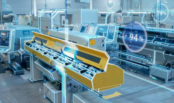

The Industry 4.0 paradigm is continuing to reshape every industrial sector. The data-driven, automated technologies that this framework leverages are having a vast and lasting impact on every single aspect of manufacturing, from R&D to operations and the entire supply chain.
BY USING THE INDUSTRIAL INTERNET OF Things (IIoT), technology is increasing the digitalisation and interconnectivity within companies as well as with their suppliers and customers in their broader value chains. In this way, it is possible to develop smart, connected industries that benefit from fully
optimised processes.
At the core of any digital journey is the ability of companies to navigate massive and ever-increasing volumes of data to gain unique, actionable insights that support real-time decision making. However, currently a key challenge for manufacturers
is implementing effective data gathering and integration solutions to support visibility, analytics and therefore optimisation. A further challenge is to ensure disparate OT systems can also communicate for the most effective process operation.
While traditional industrial Ethernet offers proven value in supporting data-driven, automated factories, its limited ability to support the smart manufacturing operations of the future is now coming into focus. In effect, the higher levels of performance, connectivity and cybersecurity required by Industry 4.0 applications can rarely be met in full by current network technologies.

Delivering convergence across the enterprise
Typically, companies have been relying on multiple networks in their operations. The shop floor, or OT level, typically features production lines or processes where multiple
17
SOURCE: ISTOCK
Download Full Version of White Paper Delivering TSN's benefits to manufacturing white paper Visit website: https://eu.cc-link.org/en/ campaign/2022/tsnwp eu.cc-link.org partners@eu.cc-link.org Delivering TSN’s benefits to manufacturing
TSN offers the potential to help in the convergence of IT and OT operations, and the use of different, non-interoperable industrial Ethernet protocols.
networks are employed. These may handle real-time process signals such as I/O, motion and safety systems. Along with these may be non-real-time traffic, such as video frames from inspection systems, barcodes, printed information, quality and maintenance data and so on. These have often required separate networks, leading to complex architectures that could be costly and time consuming to install, operate and maintain. As a result, there is often a limited ability to provide the level of transparency required to control processes in an optimum way. When it comes to sharing this data with higher level IT systems to make it available across the enterprise, managing the multiple streams and combining them has also been difficult.
Allowing all the devices and systems involved to all talk on the same OT network architecture and to the upper-level IT systems, where required, can be addressed by employing a converged approach. As we have seen, convergence allows everything to share the same network architecture to communicate and hence avoids the complexity and cost of multiple networks.
By doing this, companies can apply the intelligence of IT to OT systems, creating an in-depth understanding of machines, processes and plant to optimise processes, drive up efficiencies and maximise productivity.
Given how the networks for these different domains were created, their convergence is often not straightforward, bringing forward key challenges and concerns that need to be overcome. More precisely, OT networks are made to deliver real-time, deterministic performance. If large volumes of non-realtime data are transmitted via the same infrastructure, this may impact the real-time data transfer performance due to traffic
conflicts, lack of bandwidth and prioritisation. This may lead to sub optimal process operations that suffer from communications bottlenecks, decreased productivity and downtime.
Such a scenario is also optimistic, as it pre-supposes that the ability to combine non-real-time and real-time process data on the same network actually exists. While many industrial Ethernet protocols offer the ability to combine multiple types of process data, such as I/O, motion and safety, the ability to combine these with other data, as described above, is often missing.
Finally, many plants have evolved over time and hence have “islands” of different, non-interoperable industrial Ethernet systems.
This further limits the ability to share data across the plant.
In summary, before companies can progress on their Industry 4.0 digitalisation journey to full process optimisation, they need a network infrastructure that addresses the following challenges:
1. Convergence of multiple types of real-time process related traffic, such as I/O, motion and safety.
2. Convergence of real-time process traffic with non-real-time traffic, such as vision system images, barcode readers, printers, quality and maintenance data and so on.
3. Convergence of different non-interoperable industrial Ethernet protocols.
4. Convergence of OT and IT systems.
5. Ensuring all this traffic is secure and protected from unauthorised access.
While conventional industrial Ethernet is not suited to address all these issues, an innovative, complementary technology can provide the right solution – TSN.

Automotive
Use of TSN for automotive assembly, along with gigabit Ethernet bandwidth, offers key advantages in the drive toward higher performance assembly operations. Automotive manufacturing facilities are known throughout industry as leaders in Industrial Ethernet automation and machine control solutions and the need for the highest levels of IT/ OT integration. The complexity of these operations, and a constant push to speed up
18
Delivering TSN’s benefits to manufacturing eu.cc-link.org partners@eu.cc-link.org
SOURCE: CLPA
TSN technology is already being implemented in various automotive applications worldwide.
TSN allows devices and systems to all talk on the same OT network architecture along with upper-level IT systems.
SOURCE: CLPA
production processes, requires excellence in networked communication, enterprise connectivity and deterministic control.

While automotive manufacturing systems handle volumes of data generated in real-time during assembly operations, TSN offers a single network with TSN-enabled components that offer resources for time-critical data transmission, while allowing less critical traffic to co-exist on the network.
Total cost of ownership can be reduced, since multiple types of networks are combined into one unified control and communication hierarchy. And importantly, the result for manufacturing operations is not only higher performance, lower costs and simplified maintenance, but also better-quality vehicles.
TSN also helps to build automotive production lines that ensure shorter cycle times, as the technology combines advanced control and synchronization with tools for prioritizing traffic. The network allows timely delivery of time-critical traffic, while allowing less critical traffic to co-exist on the network.
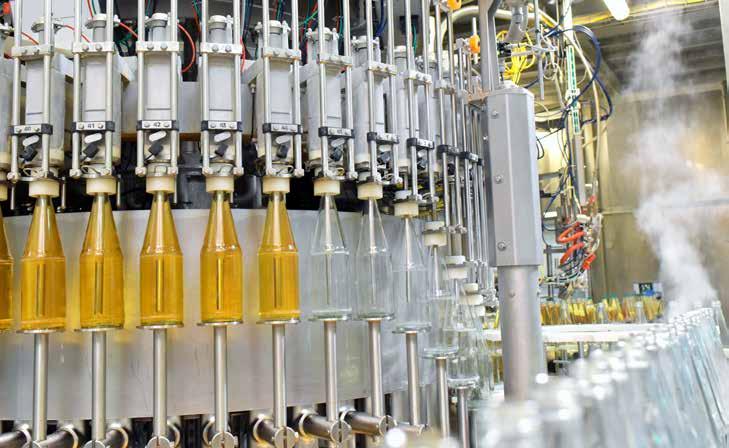
Food & beverage
The food and beverage sector requires high production speed and volume to be profitable. Smart manufacturing is becoming a key topic to help meet these goals – and data is the enabler for this trend. Processes can only be run at the highest productivity when there is the necessary visibility of how close they are to maximum efficiency and what needs to be done to close this gap.
TSN addresses challenges in food and beverage applications by providing the potential for a high degree of process transparency despite the use of many different systems across a plant by implementing a converged, gigabit communications architecture.

It offers the opportunity for all systems from batching, mixing, forming, through to packaging to share information, thus providing the ability to see the big picture necessary to run a plant or line at maximum efficiency. Possible data islands caused by dissimilar systems may also be addressed by combining the traffic from different equipment onto the same network. This can ultimately all be combined into a common stream of data that is more easily shared with higher level supervisory systems and consequently allowing actionable insights to be derived to feed back into the processes for complete optimisation. AI is increasingly becoming a topic for the industry, and supplying these systems with the large volumes of process data required to derive the necessary process insights and corrective actions will become easier when supplied by TSN communication architectures.
TSN also provides the foundation of more secure processes by making it simpler to monitor process data when converged onto a single architecture. Hence unauthorised
actions can be detected more quickly and processes safeguarded in real-time.
Lithium battery
The lithium battery industry has seen exponential growth over the past several
years as the automotive industry, in response to environmental pressures, has been racing to implement electric powertrains. This trend is set to continue. Hence the ability of the industry to respond to this continually rising demand is critical to its success. Being able to
CLPA - a partner in advancing industry-wide TSN conformance
The CC-Link Partner Association (CLPA) is actively engaged with Avnu Alliance, ODVA, OPC Foundation (OPCF) and PROFIBUS & PROFINET International (PI) as part of the TSN Industrial Automation Conformance Collaboration (TIACC). The organisations will work together to develop a unified conformance test plan for automation devices that leverage TSN, driving standardisation, interoperability and interconnectivity.
Bringing together key global industrial network and communications specialists, the TIACC is an industry-wide initiative aimed at developing a solution for TSN conformance. The CLPA, collectively with all other leading organisations, will develop and agree a single common conformance test plan to certify TSN-compatible products, in line with the IEC/ IEEE 60802 TSN profile for Industrial Automation.
The resulting methodology and practices will be released for use to the entire industrial automation ecosystem. By doing so, the TIACC partners will promote the alignment of TSN-compatible solutions from different vendors, which is essential for the development of converged industrial automation networks.
19 eu.cc-link.org partners@eu.cc-link.org Delivering TSN’s benefits to manufacturing
SOURCE: CLPA
The food and beverage sector requires high production speeds and maximum uptime.
SOURCE: ISTOCK
HMS adds to the CC-Link IE TSN development ecosystem
Anybus® CompactCom 40 CC-Link IE TSN adds to the range of development options for device vendors developing CC-Link IE TSN products.

The CC-Link Partner Association’s (CLPA) partner, HMS Networks, announced the release of a new embedded development option for designers of industrial automation devices compatible with CC-Link IE TSN. The Anybus CompactCom 40 CC-Link IE TSN embedded communication interface provides a gigabit Ethernet connection and TSN functionality in one package. With CompactCom 40 CC-Link IE TSN, device manufacturers and machine builders get a fast track to connecting their products to CC-Link IE TSNs networks for future-proof applications.
Benefits of TSN
CC-Link IE TSN is the first open industrial network protocol to combine gigabit Ethernet bandwidth with TSN functionality, delivering the advances of network convergence. Using the new Anybus device, product developers now have increased options when it comes to designing products that can take advantage of these benefits. The device can easily be designed into new products, or provide a convenient upgrade path for companies already using Anybus interfaces.
add manufacturing capacity while maintaining cell quality are key challenges.
TSN is especially suited to addressing these challenges. The ability to offer a converged network architecture with gigabit bandwidth means that it’s possible to have high performance motion traffic for possibly hundreds of axes run over the same network
Fast, reliable communication
The CLPA supported HMS Networks in the development of Anybus CompactCom 40 CC-Link IE TSN, which is a fully compatible TSN product supporting certification class B. The award-winning Anybus NP40 industrial network processor is at the core of the CompactCom, ensuring high performance by transferring up to 1420 bytes of process data in each direction and guaranteeing synchronization accuracy of 1 μs or less.
As with all Anybus CompactCom 40 products,
as other types of machine control, while also integrating vision, safety and other systems. These may all coexist on the same network without compromising performance or quality.
Water treatment
The water industry is turning to digitalisation to assure its success and initiatives like
Download Complete White Paper
Download the full white paper, Delivering TSN’s Benefits to Manufacturing, and find out how Time-Sensitive Networking enables the converged network architectures that will address the requirements of modern production plants, and deliver multiple benefits to manufacturers in every sector.
Learn how TSN technology offers specific benefits for smart manufacturing.
Download the white paper today to read the full story!
https://eu.cc-link.org/en/ campaign/2022/tsnwp
the CC-Link IE TSN interface is available in different formats, enabling customers to choose the form factor that suits their needs.
• Module: An all-in-one solution that enables the fastest time to market. It includes hardware, firmware, as well as connectors, and is available with or without housing.
• Brick: Hardware and firmware packaged in a very compact brick form factor. This is the best choice for applications with limited space, and if a specific connector or protection class is required.
“Water 4.0” are examples of this. Processes such as chemical dosing need to be further optimised. Vast supply networks benefit from intelligent data acquisition which in turn raises the issue of handling the huge amounts of data they generate. Cybersecurity is a key topic.
TSN is well placed to help the industry address these kinds of challenges. When it comes to building large scale control and monitoring networks, the ability to combine multiple types of device traffic on a single network architecture will make the task of reducing operating costs easier. Moreover, these deterministic, converged networks with gigabit bandwidth will help to ensure processes are optimised in real-time by getting data out of the processes to edge servers and cloud based supervisory systems more easily and making the application of corrective actions quicker.
Time-Sensitive Networking also helps to address cybersecurity by providing a foundation for easier implementation of standards, such as ISA/IEC 62443, and supporting techniques such as zoning, band limitation and filtering, intrusion detection and so.

20 Download White Paper
Delivering TSN’s benefits to manufacturing eu.cc-link.org partners@eu.cc-link.org
SOURCE: CLPA
Ethernet & TSN – switching connectivity up a gear
TSN is an enabling technology and a vehicle for broader change in industrial networking that prepare Ethernet for next-generation applications. Its key benefit is its ability to facilitate the creation of open, unified, convergent architectures that provide the opportunity to realise vast productivity improvements.
TO LEVERAGE THE COMPLETE VALUE PROPOSITION of TSN, it is essential for end devices as well as infrastructures to support this technology. So it is no surprise that compatible, certified network switches have already been released.
Thomas Rodenbusch-Mohr, Product Cluster Manager at CC-Link Partner Association (CLPA)’s partner Hirschmann Automation and Control GmbH – a Belden Brand, discusses the benefits of TSN and why the company is offering compatible products.
Convergence is most certainly a core aspect of future-oriented smart applications in a variety of sectors, from manufacturing to transportation and energy automation. TSN can enable this, with its ability to deliver highly deterministic communications within standard, vendor-neutral Ethernet.
“TSN can distinguish traffic, assigning priority levels to individual data packets and sending each stream over the network accordingly while observing their individual timing constraints. This means that TSN can cater to even the highest real-time communications demands of industrial automation applications,” Rodenbusch-Mohr says.
In particular, TSN supports the integration of information technology (IT) and operational technology (OT). “This innovation supports network convergence by allowing users to merge IT and OT traffic on the same wire, while still satisfying their individual communications requirements. In effect, a key added benefit that TSN brings to industrial applications is the ability to drive the unification of networks that were, out of necessity, kept separate in the past. This affords a reduction in network complexity and capex investment. More importantly, the broader technology change that comes alongside TSN enables the creation of open network architectures. This will reveal a real treasure trove of information that data scientists can leverage to support Industry 4.0 and smart applications. By making this information seamlessly accessible directly from the source, there is no need for gateways in between,” he said.
Additional features of TSN that are of high value to users, automation and machine vendors include backward and forward compatibility, which makes it possible to integrate existing and future Ethernet devices in TSN-capable networks with suitable,
comprehensive migration paths. Further to this, newly introduced TSN mechanisms are additions to the Ethernet toolbox and offer the same network architecture flexibility and bandwidth scaling of traditional Ethernet.
Creating the connected industries of the future

These competitive advantages are the foundation of cost-effective, cuttingedge networking capabilities. Factory and process automation are perhaps the fields that can benefit most from TSN technology and the changes it can bring. Thomas adds: “For example, you can have critical traffic, like motion control, with precise real-time demands and traffic without real-time demands, such as bandwidth-consuming file transfers, running simultaneously on the same network without interfering with each other.“
“Ultimately, network convergence enables distributed real-time control. As a result, complex machinery and numerous robots can interact with each other with higher precision and flexibility than previously possible. Organisations can also advance key applications, such as predictive maintenance, that require the analysis of substantial volumes of sensor data. An open and converged network from the Cloud to shop floor sensors also provides secure access to perform maintenance and other tasks
remotely.”
Besides, TSN offers highly accurate time synchronization (IEEE 802.1AS) and mechanisms to control bandwidth utilisation. These can be extremely relevant in discrete applications as well as within process automation networks, providing accurate time for applications based on sequences of events.
Seizing the opportunity
Belden and its brand Hirschmann were among the first adopters of TSN to futureproof their products and customers’ systems. Thomas observes: “Belden is constantly pushing the boundaries of technology and, with this goal in mind, was among the standardisation initiators of TSN at the IEEE in the early 2010s. With products built on the strong foundation of standard Ethernet, TSN is a natural fit to Belden’s portfolio, which comprises marketleading industrial networking solutions that are used in the most challenging environments.”
When looking at developing their first TSN-compatible products, Belden’s RSPE and BOBCAT Managed DIN-Rail switches, the company selected CC-Link IE TSN as its underlying technology, the first open gigabit industrial Ethernet with TSN functions. “Of course, the fact that the CLPA offered the first industrial TSN profile available for certification played a prominent role in our decision. In addition, the organisation made good use of the new TSN additions to the Ethernet toolbox and selected the appropriate mechanisms to provide suitable communications over a vendor-neutral networking technology. This forward-looking vision empowered the CLPA to be ahead of many others with regards to specification and certification.
“In practice, it offers the most advanced ecosystem of TSN-compatible devices and controllers as well as clear migration paths for existing devices in CC-Link IE TSN networks. These features give vendors a unique opportunity to certify and upgrade their product portfolios with the technology while helping machine operators smoothly transition towards complete TSN-capable environments. In addition, CC-Link IE TSN offers low complexity configurations and early certification routes,” summarises Thomas Rodenbusch-Mohr.
21 eu.cc-link.org partners@eu.cc-link.org Delivering TSN’s benefits to manufacturing
SOURCE: ISTOCK/GORODENKOFF
TSN can cater to the real-time communication demands of industrial automation applications.
CC-LINK IE TSN: ONE NETWORK. ONE SOLUTION.
Combine Time-Sensitive Networking with gigabit bandwidth to create open, converged industrial Ethernet architectures that deliver significant business benefits, including:

n Simpler network architectures/machine designs
n Greater process transparency and better management
n Better integration of OT and IT systems
CC-Link IE TSN is ready to deliver these productivity benefits now to support your drive to Industry 4.0.
Learn how by scanning the code, visiting eu.cc-link.org or contacting us at partners@eu.cc-link.org
How TSN is being applied in real world manufacturing
When it comes to implementing a TSN-capable application, a thorough understanding of the existing application requirements and network topology is a prerequisite to choosing the most suitable protocol and the right configurations for the switches and end devices.
IN RECENT YEARS, TIME-SENSITIVE NETWORKING (TSN) has leapt from the pages of academic journals to practical applications in the real world. Companies that want to reap the benefits of this exciting technology must understand the needs of industry players and start to build TSN-enabled systems.
Even before the formation of the IEEE TSN task group, Moxa has been working with industry partners to promote digitalization in the manufacturing sector, also known as Industry 4.0, and all the key technologies for industrial automation. TSN is a crucial enabler of industrial digitization applications where Moxa has already made valuable contributions. In fact, Moxa has partnered with numerous industry stakeholders to build TSN-enabled systems and bring the proven benefits of TSN to the factory floor through several technological advances and real-world applications.
Common Time Referencing
Traditionally, different equipment, interfaces, and protocols presented serious challenges to transmitting, receiving, and processing large amounts of data in a timely manner for industrial automation applications. TSN overcomes these challenges by enabling
time synchronization on the network so that all connected devices share a common time reference for all data to become available at a given point in time for specific tasks. These TSN-enabled systems are highly reliable as built-in bounded low latency in a deterministic networking environment optimizes performance and security.
To achieve a high level of reliability, IEEE 802.1CB Frame Replication and Elimination for Reliability (FRER) works to send duplicate copies of each frame over multiple disjoint paths, so even in the event of partial network failure, proactive redundancy still allows for seamless communication. During Taipei automation 2022, Moxa partnered with NXP Semiconductors N.V., a Dutch semiconductor designer and manufacturer and port Industrial Automation GmbH, to test the reliability of an 802.1CB-based ring topology that used Moxa switches to connect NXP equipment.
As engineers unplugged certain network cables to simulate network failure, the data packets that controlled the critical equipment still synchronized and operated normally. Moreover, this test also demonstrated that robust network redundancy helps recover multiple points of failure, not just a single point of failure.
Another important step toward implementing TSN in industrial automation is to ensure the data can be transmitted in wireless applications. As a lot of industrial equipment is mobile, true IIoT will not be possible without a wider array of TSN wireless applications. In Taipei Automation 2021, Moxa, Intel, and port Industrial Automation GmbH developed a platform that demonstrates the industry’s first ready-to-use, applicationto-application TSN solution for instant transmission of data.
Designed to be compatible with various communication protocols, the new platform is flexible and expandable, which means it can be used to build a next generation of smart manufacturing and logistics solutions, particularly when mobile devices are not only desired but required in real-world use cases. Wireless TSN fleshes out the full potential of TSN as a truly unified and high-performance network infrastructure that allows all types of traffic to coexist.
Taking TSN further
In addition to proving that the technology works, Moxa has also implemented TSN in several real-world applications to help companies achieve tangible business benefits.
23 03.2023 industrial ethernet book
SOURCE: MOXA
TSN Technology
A key to the ongoing development of TSN applications for manufacturing is dependent on a strong ecosystem of TSN-enabled devices and systems
Wafer Manufacturing: Cooperating with ELS System Technology, a leading Taiwanese lithography solution provider, Moxa successfully integrated TSN into the wafer manufacturing process. The system incorporates machine vision into the wafer misalignment correction system. The TSN technology successfully integrated a high-bandwidth video application with a highreliability on-demand motion control CC-Link IE TSN.
The solution delivered a stable motion control system, fully equipped with machine vision, for the misalignment correction system. Moxa’s TSN solution also supports different types of traffic that may have very different requirements and offers accurate motion control data about network traffic in real time using the same open and standard network. What’s more, the TSN solution also helps increase the economic feasibility of the network and reduces the total cost of ownership (TCO) as the infrastructure is easy to maintain and scale up.
Video Component Logging: Real-time video monitoring is notoriously data- and bandwidthhungry. TSN’s ultra-reliability and bounded low latency make building a converged application for recording and streaming live video over a network a feasible task. To help the Japanese industrial conglomerate Mitsubishi Electric improve the logging of all system components during visual inspections, Moxa built a module with the capability to record the video stream, waveform, and related information to help users speed up troubleshooting when necessary.
As they are no longer required to scour through different devices or networks, Mitsubishi engineers can now conduct their forensic investigation on a TSN-based
integrated system in which critical and synchronized visual data is safely accessed, stored, and protected.
How TSN helps
TSN is the key to smart factory automation because deterministic, real-time communication allows different equipment to work seamlessly together. As networks grow in size and complexity, TSN implements traffic management and prioritizes system resources to ensure that critical data gets delivered on time, which makes the network ultra-reliable and more secure.
Let's now consider two use cases that showcase the capabilities of TSN, and how Moxa works with system integrators, machine builders, and end users to achieve better returns with TSN.
Use Case 1: Responding to market demands for advanced, integrated, and highly automated machinery, machinery manufacturers aim to offer machinery that features built-in scalability, accelerated sensing, and complex laser and machine control applications. As such, however, different proprietary networks belonging to different components require seamless communication and integration in order to deliver optimal performance. Furthermore, the maintenance of these networks will present challenges for operators, especially when the machines are shipped abroad and training for operators is at times not followed through.
Moxa developed a unified TSN network to enable deterministic communication between cameras, sensors, and machine controls.
Moxa’s TSN-G5008 Series full Gigabit managed switch connects multiple I/Os to the servo drivers and machine vision cameras. Due to
the “first-in, first-served” nature of Ethernet, it was not possible to transmit critical data on the same cable. With standard Ethernet TSN infrastructure, however, traffic management now allows critical data to share networking resources and ensures data packet delivery. The switch is designed to make manufacturing networks, such as those of machinery manufacturers, compatible with TSN to reap the benefits of Industry 4.0.
Use Case 2: A shorter production cycle is beneficial to businesses because efficiency leads to lower costs and more flexibility. It also allows businesses to cater to a changing market and offer mass customized—and often higher margin—products, such as commercial-off-the-shelf (COTS) products. For manufacturers, such efficiency and flexibility can only be achieved when various systems— including production, assembly lines, and logistics—are on a unified network so changes and adjustments to the production and distribution processes can be implemented on short notice more effectively.
To make mass customization possible, manufacturers can deploy Moxa’s TSN-G5004 and TSN-G5008 Series Ethernet switches to combine existing proprietary networks into a single TSN-capable network to boost efficiency. Most importantly, manufacturers can achieve information technology (IT) and operational technology (OT) convergence, so as to reduce the number of processes required to make a product. As such, adaptive production, mass customization, and production optimization are enabled because assets are managed through a TSN-enabled network, with which deterministic communication ensures effective control over the entire manufacturing process.
A simplified network topography benefits
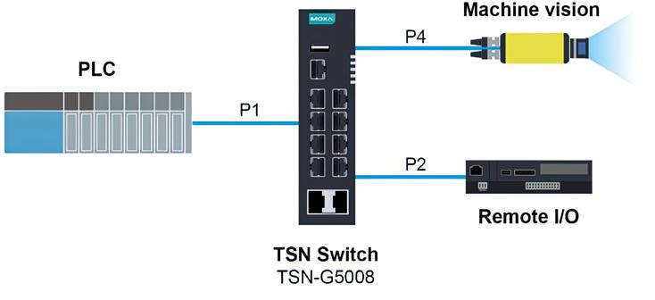
24 industrial ethernet book 03.2023 SOURCE: MOXA TSN Technology
Moxa's TSN switch allows data to be sent between the PLC and end devices.
operators because maintenance becomes easier and more cost effective. As operators now maintain a unified network instead of many networks with different protocols and requirements, training can be streamlined. Cabling, too, becomes more straightforward, contributing to lower maintenance costs.
Stakeholders that benefit from TSN TSN brings efficiency, easier management, and cost effectiveness to the world of industrial automation. Its deterministic communication, whether wired or wireless, contributes to the ultra-reliability needed for high-stakes and demanding industrial systems. As TSN requires a standard, unified network for different devices, IT and OT convergence offers fewer nodes, streamlined cabling, and easier maintenance. These benefits are realized by a wide range of stakeholders from machine builders to system integrators to end-users.
Machine Builders: With TSN technology, machine builders can leverage a competitive network infrastructure that allows the motion bus and information being sent across the network to be converged on the same cable. This simplified architecture can also reduce the number of nodes thereby saving overall costs and maintenance effort.
In addition, from the performance standpoint, the cycle time of the control loop can be shortened, which makes it possible to control more devices. Last, since TSN technology runs on a Gigabit network, the higher bandwidth is well-suited for adding more applications in the future.
System Integrators: The unified TSN network
also simplifies network and automation architecture by reducing cabling and engineering efforts. TSN’s ability to converge all proprietary networking technologies into one single cable means that network planning and scale can be controlled and predicted, thereby reducing the total cost of ownership and saving maintenance efforts.
End-Users: TSN is compatible with existing networks so additional network gateways that connect to different proprietary systems are no longer required. In fact, TSN’s compatibility with existing standard networks enables easy data access so that the system can more easily optimize resources and effort for end-users. Compared to other existing networking technologies, TSN is also better equipped to prioritize critical packets over non-critical but high-bandwidth consuming applications, which reduces overall system downtime.
Last but not least, leveraging standard Ethernet technologies means that the latest cybersecurity solutions developed for Ethernet are also available to TSN networks, offering greater protection and adaptability in an everchanging threat climate.
Preparing for TSN adoption
When it comes to implementing a TSN-capable application, a thorough understanding of the existing application requirements and network topology is a prerequisite to choosing the most suitable protocol and the right configurations for the switches and end devices.

Let us consider an example that requires both PLC communications and image capture. This application would require transmitting
two types of data to the same host computer. Using a combined network topology, it is clear that the video stream is sent from port 4 to port 1, while the controller sends the synchronization message to the master server from port 2 to port 1.
Protecting the control packet from the high bandwidth video stream requires configuring the necessary protocols on the network, including time synchronization (802.1 AS) and time aware shaper (802.1 Qbv) on the related components and ports.
The control packet is sent at 1 second cycles, 300 µs for cycle date, and 200 µs for time sync data while the remaining 500 µs is running the non-cyclic data. The device can assign the corresponding VLAN ID to each slot to ensure that the cycle data will not be affected.After clarifying the behavior of the application, the last step is to configure the necessary configurations on the Ethernet switch and end device.
Moxa has been working to ensure that TSN technologies are achieving their true potential and helping industry leaders accelerate their digital transformation in industrial automation. Through the use cases we considered in this article, we hope you have a better understanding of how Moxa has worked with trusted partners and reputable stakeholders to offer future-proof TSN solutions to clients that are at different stages of their digital transformation.
25 03.2023 industrial ethernet book TSN Technology
Technology report by Moxa. Visit Website
SOURCE: ISTOCK
As networks grow in size and complexity, TSN implements traffic management and prioritizes system resources to ensure that critical data gets delivered on time, which makes the network ultra-reliable and more secure.
TSN: five ways IEEE standards will advance Industry 4.0
Because TSN is the first step to breaking down existing data siloes that hinder industrial communications, it can enable ubiquitous access to precious, decision-making data. TSN can also be viewed as a jumping off point for helping industrial organizations achieve the promise of Industry 4.0.
ACROSS THE WORLD, I MEET WITH CUSTOMERS investing hundreds of thousands, even millions, into making the promise of Industry 4.0 a reality. This new paradigm of ubiquitous connectivity is inspiring manufacturers, from the largest automation OEMs to emerging businesses. They see the potential to make their businesses more productive, efficient, adaptable, and profitable for the bottom line and ultimately for their employees, stakeholders, and customers.
Industry 4.0 promises unprecedented levels of flexibility that translate into agile production by allowing manufacturers to adapt to seasonal or changing customer needs, for example.

We will be able to improve uptime (which controls overhead and maintenance costs), reduce resource time and involvement, and boost business and customer confidence. These are just a few examples of potentially industry-changing outcomes we can anticipate as a result of the fourth industrial revolution.
Underscoring these massive opportunities is the need to acquire, communicate, and analyze data. Data, and most importantly the insights extracted from that data, is the currency by which all of these improvements can be obtained. However, in most factories today, data lives in siloes where it sits
isolated and inaccessible—and, therefore, unactionable. For years, manufacturers have tried to solve for this, but working in siloes has stunted these projects.
Enter time sensitive networking (TSN), a set of IEEE Ethernet standards that is foundational for meeting the many powerful outcomes of Industry 4.0. With TSN, all data across the
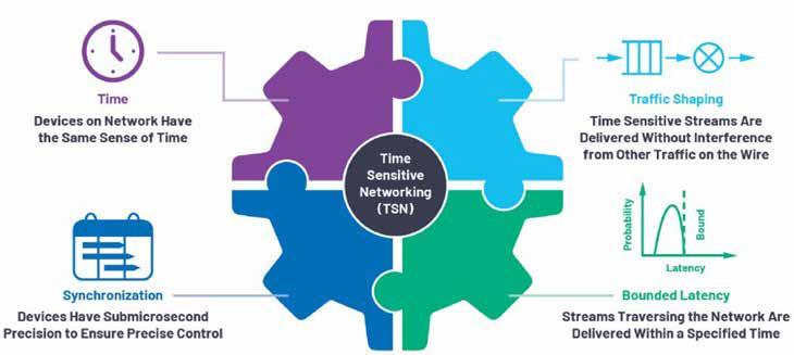
factory—from the floor to servers, front office, and everywhere in between— can coexist and communicate.
Because TSN is the first step to breaking down existing data siloes that hinder industrial communications, it can enable ubiquitous access to precious, decision-making data. TSN is the jumping off point for helping
26
industrial ethernet book 03.2023
SOURCE: ANALOG DEVICES
TSN Technology
Time sensitive networks solve the four main requirements of time, traffic shaping, synchronization, and bounded latency.
TSN provides technology solutions for the challenges of IT-OT convergence.
SOURCE: ISTOCK
industrial organizations achieve the promise of Industry 4.0 in five key ways, all rooted in making data more accessible.
Creates a common language
By creating a uniform understanding of time synchronization—and uniform treatment of all data packets and information—Time-Sensitive Networking allows data to speak a common language.
While equipment interoperability challenges will still exist, manufacturers will be able to derive more value from their data that can now all coexist in the same Ethernet path.
Enables scalability and agility
TSN can help Ethernet manage a range of transmission rates for data sends so that there is enough bandwidth for data throughput at all priority levels. Ultimately, manufacturers can add or reduce capacity more easily and adapt to changing customer priorities and needs.
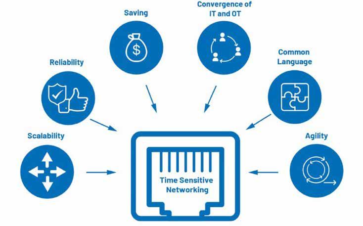
Supports more reliable automation. TSN supports the real-time, deterministic data crucial for accuracy and precision. If the timing of a data point (for example, a signal) is delayed or off in any way, a machine may not respond properly and cause downstream impacts that decrease productivity and result in lost revenue.
Consider, for example, the precision required for a robot to work alongside a human; if the robot’s movements are off by even a fraction
of an inch, worker safety can be jeopardized. TSN facilitates instantaneous communication applications like this and many more to improve safety and quality.
Helps close the divide between IT and OT specialists
By providing a common set of tools, TSN supports the often distinct and competing goals of IT and OT teams. It presents a common framework, a shared language, that supports collaboration.
Additionally, we’re seeing many OT specialists near retirement age, meaning they’ll take their historical expertise of today’s field buses to retirement with them. TSN has the potential to solve for these future skills gaps by providing a common framework that enables IT specialists to support Industrial Ethernet. This saves resources and can increase productivity.
Allows companies to allocate their R&D spend elsewhere
Since TSN solves for bandwidth constraints, companies no longer need to build new bandwidth allocations when they try to scale up or add new capacity. We’ve seen companies invest tens of millions in infrastructure that becomes obsolete or ineffective just a decade later.
TSN dramatically reduces the need for rebuilding and thus creates opportunity for
investment in technologies that support greater automation. It frees up capital for reinvestment in upskilling employees by training them to manage and operate complex robotic systems, for example.
Analog Devices offers a wide portfolio in TSN Ethernet solutions that enable the Industry 4.0 revolution.
Conclusion
There is no doubt that TSN standards are a crucial, foundational building block for the promise of Industry 4.0 and the many applications it will transform—ushering in the next generation of technology to revolutionize how manufacturers work and operate. Yet it’s just one piece of a broader ecosystem we’re building to bring the fourth industrial revolution to life.
That requires software, middleware, advanced silicon components, brilliant inventors and engineers, dedicated technicians and operators, education, and time. But my colleagues at Analog Devices and across the industry believe in the incredible potential of these emerging technologies and, like our customers and partners, feel inspired by the nearly endless opportunity.
27 03.2023 industrial ethernet book TSN Technology
Jordon Woods, Director of Deterministic Ethernet Technology, Analog Devices.
Visit Website
SOURCE: ANALOG DEVICES
Requirements for time-sensitive networks.
TSN preemption for cyclic EtherNet/IP communication
Edge computing and Industrial IoT expert Jim White, IOTech's CTO, provides his Top Five predictions and honorable mentions for the coming year, including forecasts related to security, hyperscalers, artificial intelligence and machine learning.
INDUSTRIAL CONTROL SYSTEMS USE ETHERNETbased protocols such as EtherNet/IP and Modbus TCP for cyclic communication to exchange process data, such as inputs, outputs, and motion commands and feedback. One limitation of Ethernet is its lack of determinism. For certain applications, like motion control, this has led to the development of protocols like SERCOS and EtherCAT, which rely on specialized hardware solutions.
Recently, Ethernet specifications have evolved to include Time Sensitive Networking (TSN) which defines features like a Time Aware Shaper (TAS) to achieve predictable transport of Ethernet packets.
However, not all cyclic communication used in industrial control systems need the determinism offered by TAS, but do require a bounded packet latency. TSN defines a feature called preemption that can address this use case.
Introduction
This article introduces an Ethernet switch simulator written in the Python programming language. A brief overview of how Ethernet
bridges (switches) operate is presented first so the reader can better understand the simulator description that follows. The high-level information of the simulator includes many Python class descriptions for simulating the behaviors of devices like switches, endpoints, and cables. Monitors are also described, allowing capture of egressing packets and analyzing bandwidth utilization.
A sample system is described (which uses store-and-forward switching, 100 MB/sec network speed, and two express traffic queues) and programmed into the simulator. Two types of devices (with differing payload sizes, packet priorities, and cyclic update rates) compose this system, sending their packets to a controller device. Simulator output is presented, both with and without interfering traffic and bandwidth analysis. Finally, some observations are presented.
Ethernet Switch Behavior
Ethernet bridging was initially defined in the 802.1D IEEE Standard for Local and Metropolitan Area Networks: Media Access Control (MAC) Bridges. Ethernet bridges (switches) relay Ethernet frames (packets)
between devices connected to switches. This is accomplished by copying Ethernet packets from one switch port to another, based on the MAC addresses in the packets.
A switch looks up the destination address contained in a packet in its forwarding, or switching, table to determine the outgoing port and egresses the packet out that port toward its intended destination.

QoS – strict priority
Strict priority is a queuing mechanism for Ethernet switches. It is defined in 802.1Q2018 Clause 8.6.8.1. In strict priority queueing, the queue with the highest number (class) has priority over the remaining queues. When multiple Ethernet frames are queued on an interface for transmission, the queue with the highest priority having an Ethernet frame ready for transmission will transmit. Ethernet frames in lower priority queues are held until the priority of their queue becomes the highest queue with a ready Ethernet frame.
TSN offers transmission selection (shaping) algorithms that can be bound to higher priority queues which determine if such a queue is served before a lower priority queue.
28 industrial ethernet book 03.2023
SOURCE:
ODVA
TSN Technology
Figure 1: Frame Preemption and Interspersing Express Traffic
Store-and-forward switching
Store-and-forward switching ensures a high level of error-free network traffic. This is because erroneous frames are not forwarded across the network. With store-and-forward switching, the switch copies each complete frame into the switch memory buffers prior to forwarding. The CRC portion of the frame is used to verify the integrity of the received frame. If an error is detected (bad CRC, too short or too long), the frame is discarded. If the frame is error free, the switch queues the frame for forwarding out the appropriate interface port.
Because an Ethernet switch, when using store-and-forward switching, must store an entire frame prior to forwarding, frame latency is dependent upon frame size. This is exacerbated when using large frames and daisy-chained architectures typically found in industrial control system designs.
Cut-through switching
Cut-through switching is where a switch starts forwarding a frame before the whole frame has been received. Compared to store-and-forward switching, cut-through switching can offer lower latency but, because the frame check sequence appears at the end of a frame, the switch is not able to verify frame integrity before forwarding it. Cut-through switching will forward corrupted frames, whereas store-and- forward switching will discard them.
Pure cut-through switching is only possible when the speed of the outgoing interface is equal to or lower than the incoming interface speed.
A switch may buffer (acting in a store-andforward manner) a frame instead of using cut-through under certain conditions:
Speed: When the outgoing port is faster than the incoming port, the switch must buffer the entire frame received from the lower-speed port before the switch can start transmitting that frame out the high-speed port, to prevent underrun. (When the outgoing port is slower than the incoming port, the switch can perform cut-through switching and start transmitting that frame before it is entirely received, although it must still buffer some of the frame).
Congestion : When a cut-through switch decides that a frame from one incoming port needs to go out through an outgoing port, but that outgoing port is already busy sending a frame from a second incoming port, the switch must buffer some or all of the frame from the first incoming port.
Frame Preemption and Interspersing Express Traffic
The purpose of preemption is to provide reduced latency transmission for time-critical frames in an Ethernet switch. Evaluation of
preemption is based on the definitions in 802.1Q-2018 Clause 6.7.2 and 802.3-2018 Section 7 Clause 99 with “express” and “preemptible” configurable in the switches for all queues on a per queue basis.
Frame Preemption specifies procedures, managed objects, and protocol extensions that define a class of service for time-critical frames that requests the transmitter in a switched Local Area Network to suspend the transmission of a non-time-critical frame and allows for one or more time-critical frames to be transmitted. When the time-critical frames have been transmitted, the transmission of the preempted frame is resumed. A non-timecritical frame could be preempted multiple times.
Figure 1-(a) shows that a large, non-timecritical frame (in blue) may start transmission ahead of the desired transmission time of time-critical frame (in green). This condition leads to excessive latency for the time-critical frame. Transmission preemption preempts the non-time-critical frame to allow the timecritical frames to be transmitted as shown in Figure 1-(b). This provides the capabilities of an application that uses scheduled frame transmission to implement a real-time control network.
Preemption examples
One or more queues related to an interface port in an Ethernet switch can be marked as express. This allows packets from these queues to preempt packets from non-express queues that are currently being egressed. However, this is limited to queues that are both lower priority and are not also marked as express.
Current Ethernet standards only allow one preemption on a port to be active at a time. So, this is unlike preemption in task scheduling of operating systems, where it is standard to allow multi-level preemption by higher priority tasks. If a packet preempts a non-express packet, the new packet cannot be preempted. Following is an example with multiple express queues:
• QueueA with priority p4, express
• QueueB with priority p3, express
• QueueC with priority p2, non-express
• QueueD with priority p1, non-express Higher values of “px” are higher priority. QueueA and queueB are marked as express. This would allow packets of priority p4 or p3 to preempt packets with priority p2 or p1. However, packets with priority p4 cannot preempt packets with priority p3. in case both queueA and queueB are ready for transmission at the same time, the packet in queueA would be selected based on priority. If the transmission of a packet from queueB has already started, packets from queueA need to wait for that transmission to complete.
As a result, the latency for packets from queueA is increased.
Preemption and Packet sizes
During Preemption, a switch splits an egressing packet into two fragments. the preemption algorithm adds a four octet Cyclic Redundancy Check (CRC) to the currently egressing fragment and adjusts the CRC in the remaining fragment to account for the reduced packet content. Preemption does not provide a padding of fragments to meet minimum Ethernet packet sizes (64 octets). Hence, a packet can be fragmented after 60 octets as long as there are 64 octets remaining. Thus, a packet must be at least 124 octets in length in order to be preemptable. Any packet of 123 octets or less cannot be preempted.
Preemption & cut-through switching
When using store-and-forward switching, the preemption algorithm knows the size of an egressing packet and can determine if sufficient octets remain in order to make a preemption decision. However, when using cut-through switching, the switch is egressing a packet as it is ingressing and the switch has no knowledge of the number of remaining octets. One workaround is to not cut-through a packet until at least 64 octets have been received. This diminishes the benefit of using cut-through switching. Another solution adopted by many switch suppliers is to only allow cut-through switching for express packets and use store-and-forward switching for non-express packets. This second approach is what is currently implemented in the Ethernet Switch Simulator.
Physical interface
Each external port of an Ethernet switch contains a physical layer interface (PHY) consisting of electronic circuit transmission technologies. It can be implemented using various hardware technologies with widely varying characteristics. It performs encoding, transmission, reception, decoding and provides galvanic isolation.
A PHY translates logical communications into hardware-specific operations to cause transmission or reception of electronic (or other) signals. This conversion increases packet latencies and may be different for a transmitter compared to a receiver. Since both transmission and reception are necessary, the Ethernet Switch Simulator uses an average value for this delay.
Interference
This section considers the effects of packets that interfere with another packet as it travels to its intended destination. Only store-andforward switching scenarios are considered. The effects of store-and-forward switching are shown in Figure 2 on the next page. A line topology is used for this demonstration. Each row in the figure represents an ingress or egress time of a packet to or from a particular device
29 03.2023 industrial ethernet book
TSN Technology
or switch in the line. A packet originator (or talker, in TSN terms) and three switches plus an end-device (which is the packet destination or target and listener in TSN terms) are shown.

Since the format of Figure 2 is used to represent packet timings, here is a brief explanation. The top of the figure represents the topology of the network being analyzed. On the left, labels describe whether the packets are ingress to or egress from a particular port on a specific switch. Rectangles, with packet labels inside, represent packet times, with time flowing from left to right. Packet labels like HP0, HP1, and so on, or ‘high priority’ represent high priority packets while terms like int0, int1, and so on, or ‘low priority’ are used to represent lower priority packets. A dimension line shows the total latency (txmt) for the packet of interest. When two switches’ ports are directly connected (for example, P2 of SW1 connected to P1 of SW2) egress from one port is equivalent to the ingress of the other. Wire speed times are not considered in any diagrams. Switches take time to calculate which packet should be forwarded next, represented by tsw. The timing of tsw is from the completion of a packet ingress to the start of a packet egress or, in the case of cut-through, after the requisite data has been received. To demonstrate maximum interference, all interfering packets in this document’s figures are depicted at the latest possible arrival time to still cause interference.
Interfering traffic can occur when a switch is already transmitting a packet out a particular port and another packet, destined for the same port, arrives. This newer packet must wait for the completion of the already in-progress packet before it can be sent, as shown in Figure 3. This form of interference can happen regardless of packet priorities.
Another form of interference is when a switch is currently egressing a packet and it receives a high priority packet, which it queues, and a lower priority packet, which it also queues. Upon completion of egressing the initial packet, the switch chooses to send the higher priority packet first, thus delaying the lower priority packet, as shown in Figure 4.
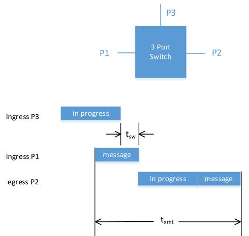
The above examples demonstrate how a packet travelling through a switch can get delayed due to interference. In order to determine maximum packet latencies, the time when packets arrive (ingress) and packet priorities must be taken into account.
In-progress interference occurs when a packet destined for a particular port arrives after the switch has already decided to send another packet out that same port. Packet priority has no effect in this case, because the decision was made prior to the arrival of a potentially higher priority packet. Assume a high- priority packet is arriving on port 1 destined for port 2 and a lower priority interfering packet is arriving from port 0 or
30 industrial ethernet book 03.2023 TSN Technology SOURCE: ODVA
Figure 2: Store-and-Forward Packet Timing.
Figure 3: Interference by Packet Already In Progress
has already been queued or is currently being transmitted out of P2.
The worst-case scenario occurs when the interfering packet is queued just prior to the switch deciding which packet to send next and the high priority packet is queued just after the switch makes this decision. In this case, the lower priority packet will be sent prior to the high priority packet. This will cause a delay of the high priority packet equivalent to the amount of time remaining to send a packet already in progress, which could be the time for the entire packet in the case of starting transmission just before the arrival (queuing) of the high-priority packet.
Without preemption, the full packet transmission time of the lower priority packet will impact the transmission of the highpriority packet. However, if the high-priority packet is express traffic and preemption criteria is met for the non-express lowerpriority packet, preemption can occur and only the initial fragment of the non-express packet will impact the transmission of the express packet. The worst- case delay occurs with the maximum non-preemptable size packet, which is 123 octets.
The latency introduced by a 123-octet packet that a switch just started to transmit, or committed to transmit, is the maximum time an output port can be blocked. A 124-octet packet could be split into two fragments after 60 octets. Any larger packet could also be split into two fragments after 60 octets.
Ethernet Switch Simulator Behavior
There are numerous Ethernet switch simulation environments available on the market, but, for various reasons (not described in this paper), the author decided to develop one from scratch using the Python programming language. The initial goal was to focus on predicting maximum latencies for various architectures and types of cyclic traffic when preemption is used. Express queues can be configured to support multiple cyclic traffic scenarios (such as motion and I/O).
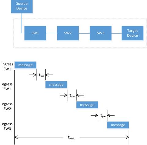
The Ethernet Switch Simulator (ESS) attempts to simulate rudimentary Ethernet switch, end device, and cable behavior in a network of switches linked together.
Current Feature Level
Currently, the ESS implements:
• Store-and-forward and cut-through switching
• Programmable port speeds
• Programmable number of ports per switch
• Eight priority queues
• Preemption
• Multiple express traffic queues
• Unicast endpoint addressing
• Bandwidth utilization measurements The current version does not support:ESS•
Redundant connections of any kind (implemented but not yet verified)
• Multicast addressing
• Non perfect internal connections of a switch (assumption is that a switch can process wire speed on all ports simultaneously)
• Time aware shaping
• Time variances between EthernetEndpoints
The Ethernet Switch Simulator allows modeling applications that consist of endpoints, switches, and cables connected together to form a network structure. Traffic patterns are preloaded into endpoints prior to running the simulation. The main architecture consists of several Python classes.
Instances of the EthernetEndpoint, EthernetSwitch, and EthernetCable classes can be connected together in the main program to form a network topology. The main program also provides the capability to define packets and packet patterns, choosing data to monitor, and calculating bandwidth utilization for selected ports.
Simulation Setup
The main program is where the system and the network traffic to simulate is defined. The current version supports multiple device types
(like controller, drive, I/O rack, and so on). In addition, safety traffic can be simulated as well. The cyclic rate to be simulated can be defined per traffic type and per device (for example, 1 msec for motion traffic and 20 msec for safety traffic). Additional traffic patterns could be added to a device type to support even more cyclic exchanges for a single device type. By having multiple device types, situations comprising multiple cyclic rates can be analyzed. A Python dictionary is used to store the desired packet information and the number of devices of each type in the system. A single value can be used for the size of packets sent and received by a particular device type or different sizes can be chosen for each device of a particular type. An offset of when a packet should be sent within a cycle is also available. This value can be static or influenced using a random number generator to simulate initial packet egress variances (jitter) in an application.
Next is to connect the various objects together to represent a system consisting of end devices, switches, and cables. In today’s industrial control environment, devices with two external switched ports (enabling easy daisy-chaining of devices) are quite common. These devices, referred to as switched endpoints, are constructed using a
31 03.2023 industrial ethernet book TSN Technology SOURCE: ODVA
Figure 4: Interference by Higher Priority Packet
three-port switch, two that are exposed to outside connections while the third istypically connected to the Central Processing Unit (CPU) of the device. Figure 5 demonstrates this architecture and will be used in a simulation example.
To create a switched endpoint, The ESS allows connecting an EthernetEndpoint directly to an EthernetSwitch without an intervening EthernetCable. This is one of the reasons the PHY delay is simulated in the EthernetCable class and not the EthernetSwitch class. While the current version of the ESS only simulates a standard Ethernet interface for this type of connection, enhancements could be made to support other EthernetEndpoint to EthernetSwitch interfaces. To connect one EthernetSwitch to another, an EthernetCable object is used.
The ESS provides several types of EgressMonitors (for example, data capture and bandwidth analysis). The next step is to decide what egress data should be captured and assign an EgressMonitor to the desired ports on an EthernetSwitch or EthernetEndpoint.
The last step before running the simulation is to preload the EthernetEndpoints with the desired packet patterns defined earlier.
Simulation
The Ethernet switch simulator works on the principle of time slicing. The variable simulationTime allows choosing the simulation duration (in nanoseconds). The variable simulationStep is used to choose the increment of time (default is 20 nanoseconds). At each time increment, the main program calls the process method in each of the aforementioned objects. This method, which is unique to each object type, analyzes packet information properties to decide if an action is required, and if so, applies that particular action. For example, in the EthernetCable object, a packet must not start to egress until the 2 PHY delays and the cable delay have been reached.
Ethernet packet classes
The main purpose of the ESS is to simulate the movement of Ethernet packets from sources to destinations, tracking salient information (like latency). Output from multiple runs of the simulator (with varying interfering packets and with preemption on or off) can be compared to evaluate the influence of interference.
The ESS uses instances of the EthernetPacketState class to track the movement of Ethernet packets from their source EthernetEndpoint to their destination EthernetEndpoint.
There are two components to an Ethernet packet (dynamic and static). The dynamic portion is stored in an instance of the EthernetPacketstate class (described later) and contains information that can vary (such as state, packetTime, source and destination
ports, to name a few) as an Ethernet packet moves within and between instances of the EthernetSwitch, EthernetCable, and EthernetEndpoint classes. The stati portion is stored in an instance of the EthernetPacket class (described later) and contains information that remains constant (such as size, priority, source, and destination addresses, to name a few).
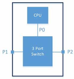
EthernetPacket Class
The EthernetPacket class contains information that remains static (except for preemption) as a packet moves through the simulated network. In case a packet is preempted, the existing EthernetPacket instance is changed to reflect the new size of the initial fragment and a new instance is created to contain the remaining fragment.
EthernetPacketState Class
The EthernetPacketState class contains information that may change as a packet moves within a EthernetSwitch, EthernetEndpoint, or EthernetCable or as it moves from one entity to another. The ESS creates new copies and destroys expired packets as a packet moves through the simulated network. Multiple copies of an EthernetPacketState class containing the same EthernetPacket may exist simultaneously. For example, an instance of an EthernetPacketState could exist for an egressing packet from an EthernetSwitch, ingressing and egressing instances within an EthernetCable, and an ingressing packet on another EthernetSwitch, all containing an exact copy of the same EthernetPacket instance.
Packet States
As an Ethernet packet moves through the simulated network, it may exist in various states during its journey. In fact, the same packet may exist in multiple states simultaneously (for example, egressing in one device while ingressing in another).
Ethernet switch simulator parameters
Many of the variables used to control the desired simulation scenario. Each of these variables can be changed in the application defining the scenario to be simulated. Various time units are provided in the output of the Ethernet Switch Simulator, but the simulator uses nanoseconds (nsec) for all internal calculations.
Addressing
To simulate packet addressing, the Ethernet Switch Simulator assigns a property of type string to instances of EthernetEndpoint classes during their creation. It uses a recursive algorithm to preassign address lookup tables in instances of EthernetSwitch classes as the network is constructed. Upon receiving a packet, the EthernetSwitch can use this information to determine the correct destination port and that no external address lookup is required.
EthernetEndpoint Class
The EthernetEndpoint is a single port device. When connected directly to an EthernetSwitch, a switched endpoint can be simulated. If connected to an EthernetCable, it can represent a device with a single Ethernet port. Prior to executing the simulation, packets are queued in EthernetEndpoints representing the Ethernet traffic to simulate.
Currently, only a single queue is implemented, so support for multi-cycle patterns, where a slower cycle pattern may need to be distributed over several fast cycles, is not supported. Note, this scenario may exist when a controller is sending packets to multiple devices at different cyclic rates.
The current queuing of packets in the ESS is designed for device to controller communication. Packets are queued cyclically, starting with data packets, followed by safety packets, if applicable, and then interfering packets (if selected). The number of interfering packets (and their size) can be configured. Interfering packets are queued in non-express queues and are used to simulate best-effort traffic that could affect cyclic traffic.
Creating Packets
The schedulePacket method is used to create packets in the EthernetEndpoint instances prior to simulation. The schedulePacket method takes the following arguments:
• pktSize: Size of packet (not including preamble or IF Gap) in octets.
• destAddr: Final destination address for packet.
• priority: Queue number for QoS, 7 being the highest, 0 the lowest.
• startTime: Desired start of egress, in nanoseconds.
• Offset: Offset from startTime for packet
32 industrial ethernet book 03.2023
SOURCE: ODVA
TSN Technology
Figure 5: Three Port Switch Diagram.
egress. Can be used to add random jitter or to represent a cyclic offset.
• pktName: name to identify packet as it traverses through the network. All packets in the simulation are uniquely named to assist in analyzing output.
EthernetCable Class
The EthernetCable class is used to simulate the delay effects of Ethernet physical interfaces and Ethernet cables. It is a two-port device supporting bidirectional packet flow. The current implementation uses 5 nsec delay for each meter of cable, representing the typical delay of twisted-pair medium. Because there is an Ethernet physical device at each end of a EthernetCable, the delay from ingress to egress is two times the physical interface delay plus 5 times the cable length.
For large packets, where the transmission time exceeds the delay calculated by the EthernetCable instance, a packet can be both ingressing and egressing at the same time. If the transmission time of the packet is shorter than the EthernetCable delay, the packet is queued in the EthernetCable instance.
EthernetSwitch Class
The EthernetSwitch class is used to simulate the behavior of an Ethernet switch (sans a physical interface, which is simulated in the EthernetCable class). Fundamentally, the EthernetSwitch is responsible for receiving an ingressing packet and, at some later time, egressing that packet out the appropriate interface port. The number of ports and their speed can be chosen when the class in instantiated. Several options (such as switching method and express queues) can also be chosen. The following sections describe the EthernetSwitch behavior based on these options.
Store-and-Forward Switching Behavior
In store-and-forward switching (without preemption), an Ethernet switch must receive the last octet of a packet before it can begin any processing of that packet. This consists of validation of its contents via a cyclic redundancy check (CRC), determining the correct egress port, and placing it in the appropriate QoS queue of that port.
The queuingTime is used to simulate the time a switch needs to perform those actions, represented by the QUEUE_PENDING state. The EthernetSwitch uses the address lookup table (created during the network construction) to decide which port should be used to later egress the packet. Upon completing of the queuingTime, the packet is placed in the appropriate queue and its state is set to QUEUED, where it remains until the time represented by the processingTime variable has elapsed. This simulates the time an
Ethernet switch needs to evaluate port queue contents to determine which packet to next egress out of a port.
Switches are constantly performing this activity, even when packets are currently egressing thus enabling contiguous egress (back-to-back) of packets separated by only an Interframe gap. The ESS simply uses this value as the minimum time a packet must be queued before it will be available for egress. When a port is not egressing a packet, the EthernetSwitch examines the queued packets in order of priority.
If a packet is ready for egress (the processingTime has expired), the packet is moved to the EGRESSING state and egress begins. Therefore, if multiple packets are simultaneously available for egress, the packet with the highest priority will be chosen. The packet will remain in the EGRESSING state until the last octet of the interframe gap time has been reached.
Cut-through Behavior
Cut-through switching can occur after a fixedlength portion of a packet (as specified in the cutThroughOctets variable) has elapsed. After this time has elapsed and if the packet’s destination queue supports cut-through, it is copied and its state is set to QUEUED, using the time provided by the CutThroughTime variable.
If the egress port is free after this time has elapsed, the EthernetSwitch begins egressing the packet while continuing to ingress the remainder of the packet. If the output port is in use (blocked) and preemption is disabled (that is, no express queues are present), the packet will be treated using store-and-forward. The ESS does not support immediate egress upon completion of the packet that blocked cut-through.
Preemption Behavior
This section describes the EthernetSwitch behavior when preemption is enabled. Two cases need to be considered; with and without cut-through switching.
When cut-through switching is enabled, only express packets utilize cut-through. Non-express packets always use store-andforward switching. This is because remaining octets are unavailable when using cut-through switching (unless the number of octets that must be received to make a cut-through decision exceed the minimum Ethernet packet length). Hence, non-express packets are treated as described in the previous section regarding store-and-forward switching.
Processing of packets with preemption enabled remains the same as described in the store-and-forward and cut-through switching sections through the QUEUE_PENDING state. Once the time expires for a packet in the QUEUE_PENDING state, it moves to
the QUEUED state. Express packets use the preemptionTime variable to decide when they can exit the QUEUED state where non-express packets use the processingTime variable as previously described.
With preemption enabled, the EthernetSwitch no longer waits until an egressing packet completes to choose which packet is egressed next, but will examine the express queues if the egressing packet is a non-express preemptable packet and is at a point where it can be successfully fragmented. If preemption can occur, the currently egressing packet is truncated and an additional 4 octets will be added to simulate the required CRC octets. The state of the fragmented packet is set to PREEMPTED_EGRESSING, its size and endTime adjusted, and the properties related to fragments in the EthernetPacket instance will be adjusted.
In addition, the remaining fragment will result in the creation of a new EthernetPacketState instance with the size of the remaining octets. The fragment properties of this instance are adjusted to indicate that this is the next fragment, the state is set to QUEUED_FRAGMENT, and it is queued for next egress (provided there are no express packets to egress). Finally, the preempting packet will egress upon completion of egressing the initial fragment.
EthernetPort Class
The EthernetPort class is instantiated for every port in an EthernetSwitch, EthernetEndpoint, and, in the future, EthernetCable class (device) instance. It is responsible for egressing and ingressing of packets, as well as understanding any connection between the devices. Understanding the connections is paramount. If a packet is egressing on a port connected to another port, then it must also be ingressing on the connected port. If preemption occurs, both ports must be adjusted to reflect the change of the preempted packet. This is one of the responsibilities of the EthernetPort class.
Simulation Example
This section will describe the use of the ESS to analyze a simple system. This simple system consists of a controller, 6 servo drives (ServoDrive 1-6), and 2 rack I/O devices (BlockI/O 1-2). This system is programmed in the ESS to analyze Ethernet packet latencies and the influence of interfering traffic. EtherNet/IP implicit cyclic messaging is used, with the servo drives communicating at a cyclic rate of 1 msec and the rack I/O communicating at a cyclic rate of 4 msec. Only device to controller traffic is considered. A baseline is first established to determine minimum packet latencies.
The focus of the analysis will be on packets from ServoDrive1 and BlockI/O1, because these are furthest from the controller and will have the greatest latencies.
33 03.2023 industrial ethernet book
TSN Technology
Packet Size
To aid users of the simulator, only the payload of packets needs to be defined. The simulator will then add 74 octets (not including header, start of frame delimiter, or interframe gap) of overhead to account for Ethernet and CIP headers.
UDP transport is assumed (50 octets) and implicit CIP I/O messaging (24 octets). If the resulting addition is less than the minimum required Ethernet packet size, 64 octets is used, because this is the minimum legal Ethernet packet size.
Device Characteristics
The device characteristics being simulated. The types of devices, cyclic packet rate, quantity, data payload, packet size, and packet priority are provided. This table is actual output from the ESS.
Two types of devices are showabove (a drive and a block I/O device). From the table, it can be seen that there 6 drives and 2 block I/O devices in the simulation. For example, the drive sends 90 octet packets (16 octets of payload and 74 octets of overhead) with a priority of 7 every 1 millisecond.
Baseline
In order to evaluate the effects of interfering traffic on cyclic traffic, a baseline, without any ancillary traffic, must first be established. This section will examine, in detail, the simulator output for two communication cycles without any interfering traffic.
The table below shows output from the ESS for the first 2 milliseconds of simulation. All times are in nanoseconds. It contains information regarding packets egressing from sw9, which is connected to the controller. Note, the simulator can capture egress packets from any port. During the first millisecond, all devices send packets while during the second millisecond, only the servo drives send packets, which are expected to be received by the controller. This is because the block I/O devices only send packets every 4 milliseconds and the servo drives send packets every 1 millisecond.
The table also illustrates the packet naming convention used by the ESS. Every packet in the simulation is given a unique name. the first portion of the name is the name of the initiating device (for example, servoDrive2, BlockIO1) followed by a packet number, which starts with 1 and is incremented each time a device sends a new packet (for example, pkt 1, pkt 2, and so on). Thus, a packet with the name servoDrive2-pkt7 is the seventh packet sent by the device named ServoDrive2.
It is interesting to note that during the first cycles, the packets from ServoDrive1 and ServoDrive2 are delayed due to the presence of the packet from the BlockI/O2 device. This is not the case for the second cycle. In a line
topology, when all devices send the same size packet at the same time, a gap is created (equivalent to the switch delay plus the PHY and cable delays) provided this gap is greater than the interframe gap time. The gap time shown in the table is represents an excess gap time, not including the interframe gap. Thus, a gap of zero means only the interframe gap is present.
The table (upper right) provides a summary of the minimum and maximum packet latencies (in nanoseconds) for the Servo Drive and Block I/O device furthest from the controller (ServoDrive1 and BlockI/O1). This table was generated by a script that uses a regular expression (shown in column 1) where the asterisk character will match all packet numbers from ServoDrive1 and Block I/O1 in the simulator output to extract minimum and maximum latencies.
Interference
The ESS can generate interfering packets to allow analyzing the effect on cyclic communication. The ESS allows specifying a single packet size, priority, and number of interfering packets per cycle. The ESS queues up interfering packets directly after each cyclic packet for each device. Hence, if 5 interfering packets are programmed, each device will send its cyclic packet followed by 5 interfering packets at the specified cyclic rate. Thus, each
servo drive would send 5 interfering packets every 1 msec cycle and each rack I/O device would send 5 interfering packets every 4 msec cycle.
The Summary, Latencies with Preempted Interference table shows the effect on packet latency for various quantity and sizes of interfering packets. Column 2 considers 5 interfering packets of size 123 octets, column 3 for 50 interfering packets of size 123 octets, column 4 for 1 750 octet interfering packet, and column 5 for 1 1500 octet interfering packet.
As expected, the largest latencies occur with 123 octet packets, because these cannot be preempted. For the larger packets, the maximum influence occurs during the first 60 or last 64 octets of transmission, because preemption cannot occur during these times. If preemption is requested during the first 60 octets of transmission, it will wait until that time before preempting.
Bandwidth Analysis
The ESS provides a capability to calculate the bandwidth utilization for individual output ports. A table shows the bandwidth utilization when no interfering packets are present and a second table shows the bandwidth utilization when 50 interfering packets are present.
For each table, four time ranges (in msec) and bandwidth (in percent) for four switches
34 industrial ethernet book 03.2023
Device type Cycle time Numdev Payload Pocket Size Priority Servodrive 1000 us 6 16 90 7 Block I/O 4000 us 2 251 325 6 Simulated Device Characteristics. Start time Start time Latency Pkt name 19680 19680 27520 ServoDrive6-pkt1 30020 1540 37860 ServoDrive5-pkt1 40360 1540 48200 ServoDrive4-pkt1 61040 11880 68880 ServoDrive3-pkt1 145040 75200 171680 BlockI/O2-pkt1 172640 0 180480 ServoDrive2-pkt1 181440 0 189280 ServoDrive1-pkt1 261260 71020 287900 BlockI/O1-pkt1 1019680 730820 27520 ServoDrive6-pkt2 1030020 1540 37860 ServoDrive5-pkt2 1040360 1540 48200 ServoDrive4-pkt2 Baseline Simulation Results. TSN Technology SOURCE: ODVA
are shown. The sw1 column represents the bandwidth on the output of sw1 connected to sw2, the sw2 column represents the bandwidth on the output of sw2 connected to sw3, the sw3 column represents the bandwidth on the output of sw3 connected to sw4, and the sw9 column represents the bandwidth on the output of sw9 connected to the controller. For the case where no interfering packets are present, the bandwidth utilization is quite reasonable. As expected, during the first msec, the bandwidth used is higher than the 2nd, 3rd, and 4th msec due to the presence of packets from the rack I/O devices.
With 50 interfering packets per cycle, the bandwidth utilization is quite different. Because the current implementation of the ESS does not support multiple queues in an EthernetEndpoint, it is important to not schedule more than 100% bandwidth utilization at an EthernetEndpoint. Because the ESS can monitor any egress port, a separate simulation (not shown) was run to determine the bandwidth usage for each EthernetEndpoint, which concluded that the servo drives with 50 interfering packets per cycle only used 58.08% of the bandwidth on the connection between the servo drive and its switch.
The Ethernet switches starting with sw3 are overloaded with packets, as demonstrated by 100% bandwidth usage, but due to priorities, the servo drive and rack I/O packets get through, albeit with some additional latency. Overloading the switches along with longer simulation times can allow the simulator to approximate worst-case latencies.
Theoretical evaluations show that the worst-case latency impact that can occur is when a 123-octet non- express packet begins egressing just before an express packet is ready for egress. This is because a packet of 123 octets is the maximum non-preemptable packet size. At 100 MB/sec, a 123-octet packet consumes approximately 11 µsec of the network (including preamble, start of header, and interframe gap). In the worst-case situation, this interference would occur at each switch (hop).
In our simulation example, interfering packets are generated by the devices, so the I/O packet from BlockI/O1 has 7 switches where this could occur (sw2 – sw8), resulting in a theoretical latency impact of 77 µsec. looking at the simulation results when interference is present the maximum latency variance is for the packet from BlockI/O1 with 50 interfering packets (approximately = 56 µsec). Further experimentation (using longer simulation times and more interfering packets) results in approaching the theoretical maximum influence. This is understandable, because the theory requires an interfering packet to begin egress just before and express packet is ready for egress at every switch.
Conclusions
This article presented simulation as one method for analyzing cyclic EtherNet/IP traffic in a network. Switch behaviors were described along with how interference can affect egressing packets. A simulator based on the Python programming language was described and its usage was demonstrated on a simple line topology network consisting of two types of traffic at different priorities and cyclic rates.
Even this simple system offers some observations which may not have been intuitively obvious; that even without interference, the packets received at the controller are not in the order of the devices on the network (that is, the packet from BlockI/O2 does not occur after the packet from ServoDrive4, but rather after the packet
from ServoDrive2). This is due to store-andforward switching and the I/O packet size being significantly larger than those of the servo drives.
Attempting to analyze even this simple system in an Excel workbook would be extremely complex, especially if one wanted to examine variance such as store-and-forward vs. cut-through, preemption vs. no preemption, packet size and priority variations, and so on.
The ESS described allows analyzing complex network topologies and cyclic data patterns by simply making a few changes to the main program file and re-running the simulation.
35 03.2023 industrial ethernet book
Visit Website Pattern Min Max ServoDrive1-pkt* 89560 6 BlockI/O1-pkt* 287900 2 Summary, baseline Minimum and Maximum Latencies Pattern 5-123 50-123 1-750 1-1500 ServoDrive1-pkt* 199540 216180 191520 190360 BlockI/O1-pkt* 318660 343620 297940 291200 Summary, Latencies with Preempted Interference Start Time End Time SW1 SW2 SW3 SW9 0 1 2.76 3.64 4.52 10.8 1 2 0 0.88 1.76 5.28 2 3 0 0.88 1.76 5.28 3 4 0 0.88 1.76 5.28 Bandwidth Analysis, 0 Interfering Packets Start Time End Time SW1 SW2 SW3 SW9 0 1 59.96 98.802 98.912 95.998 1 2 0 77.318 100 100 2 3 0 58.08 100 100 3 4 0 58.08 100 100 Bandwidth Analysis, 50 Interfering Packets TSN Technology SOURCE: ODVA
Rick Blair, Senior Principal Network System Architect, Schneider Electric.
2023 Factory Automation Connectivity Showcase
This Connectivity Showcase presents the viewpoints of eight industry experts. With Factory Automation Connectivity Solutions, manufacturers are collecting data in real-time to monitor, track, and optimize production processes, and improve safety, reduce downtime and increase production speed and efficiency.
FACTORY AUTOMATION CONNECTIVITY

solutions are at the heart of how smart manufacturing systems operate, and are mission-critical technology for the Connected Factory.
In this special showcase, the Industrial Ethernet Book has reached out to industry experts to gain their insights into Factory Automation Connectivity Solutions that are ushering in new levels of factory and IIoT connectivity.
Focus on Network Management Tools
User accounts and access control can be managed from one central user interface.
“Managed switches and gigabit speeds on the plant floor combined with security features that allow the industrial application to meet the IT requirements for things like RADIUS authentication with 802.1X support, 802.1Q and password policies,” Barry Turner, Technical Business Development Manager at Red Lion said.
He added that, in a factory application,
there will likely be a large number of switches that need to be managed and maintained by a group of controls/IT engineers.
“A really great security practices is to remove anything from the network that is no longer needed and that would include past employee log in user accounts or accounts that have been compromised,” Turner said. “Without technology like RADIUS someone would have to log onto each and every switch and remove the account to secure the network.”
Turner said that RADIUS is simply a server that the networking switches will offload their authentication to for access to the network, meaning that user accounts and access control can be managed from one central user interface. RADIUS and 802.1x make it possible to only allow authenticated users onto the controls network, thus minimizing the attack surface of the overall network. This also minimizes the chances of a 3rd party contractor connecting to your controls network with an IP address he used on his last job, which also happens to be your main PLCs IP address. Using technologies to
minimize attack surfaces like RADIUS is a smart thing to do and more customers are doing just that.
Unique technology
“As IIoT has exploded, so has the need for connectivity devices to make those application accessible via wired Ethernet, Wi-Fi and Cellular. User management and access control should be the most important component of your cybersecurity strategy,” he said. “Therefore, utilizing RADIUS technology that has proven itself to be a secure and reliable means of centralized authentication and access control is key. The more IIoT devices in the application the more switches and gateways require connectivity and access.”
The IT department is likely already using RADIUS in other applications and could easily make it where when a 3rd party contractor plugs his laptop into the controls network incorrectly it never negatively impacts your application. The contractor is simply dumped into a guest network with limited access and will eventually have to log in correctly to do the work required.
36 industrial ethernet book 03.2023
Connected Factory
SOURCE: STOCK
“As IIoT has exploded, so has the need for connectivity devices to make those application accessible via wired Ethernet, Wi-Fi and cellular. User management and access control should be the most important component of a cybersecurity strategy,” Barry Turner, Technical Business Development Manager, Red Lion.
Applications focus
Turner added that any network can benefit from using 802.1X and RADIUS to ensure that those who connect to the network are authenticated. Traditional Ethernet simply passes traffic from switch to switch. The use of 802.1x will ensure that those connecting to a port are supposed to be part of the network, and then give them access to only the part of the network allowed by administrator.
“An objective should be to minimize attack surfaces on the network. Any Ethernet port on your network is an attack surface and should be locked down in some way. The simplest way is to disable all unused ports. Another best practice is to use port security to only allow the mac addresses of the devices in your application to communication across the Ethernet switch. A more scalable approach is to use RADIUS and 802.1x,” he said.
Challenges automation engineers face
“The need for more data. Data on the controls side is quite a bit different than data on the IT side. In the industrial side, the packets are much smaller; but there are much more of them creating high packet per second between segments,” Turner said.
“Gigabit speeds along with port aggregation

will allow the network to grow with the demand for more data. High speeds allow connectivity to more of your industrial data. Industrial Ethernet switches like Red Lion’s N-Tron series NT5000 switch provides gigabit speeds in an easy to use UI that makes it easier than ever to align with the security policies of the IT department. All this in a product designed specifically for the industrial space.”
Emergence of SPE
Continuous Ethernet-based communication from the sensor to the cloud.
Dipl.-Wirt-Ing. Verena Neuhaus, Manager Product Marketing Data Connectors, for Phoenix Contact said that vendors are building connectivity options that leverage the Industrial Ethernet ecosystem and are looking to Single Pair Ethernet technology.
“In recent years, Ethernet technology has established itself as the leading communication infrastructure in almost all areas of factory automation. Various Ethernet-based protocols have long been established at the management and control level, but fieldbus-based protocols are still often used at the field level due to the different requirements placed on the systems,”
Neuhaus said.
“Single Pair Ethernet starts right there and scores with new standards, including longer transmission distances, simplified cabling and miniaturized components. This offers the possibility of continuous Ethernetbased communication from the sensor to the cloud. This saves gateways and simplifies communication structures within the networks,”
SPE benefits
Neuhaus said that Single Pair Ethernet (SPE) primarily offers the advantage of consistent Ethernet-based communication. Areas at the field level, which were previously controlled with analogue signals or based on fieldbus communication, can now also be integrated into the network using IP.
The reduction to just one pair of wires also opens up new possibilities in terms of miniaturization. Connectors and components on the printed circuit board are becoming smaller and thus enable a higher packing density - this means that smaller devices can be implemented.
The connection in the field is made much easier by reducing from eight to just two wires and can therefore be carried out in less time.
37 03.2023 industrial ethernet book Connected Factory
SOURCE: PHOENIX CONTACT
“Devices are becoming more intelligent and with increased demands for efficiency and costs, more information has to be exchanged between devices. The consequence is smart networks that allow intelligent, data-based evaluation and therefore also require more data interfaces,” Verena Neuhaus, Manager Product Marketing Data Connectors, Phoenix Contact.
And raw materials such as copper are also saved thanks to the simple cable structure; this has a direct impact on the issue of sustainability.
“The original motivation for Single Pair Ethernet came from the automotive market a few years ago. Complex wiring harnesses for more and more sensor technology in the automobile required new solutions - these were the beginnings of automotive Ethernet,” Neuhaus said.
“With the definition of new standards within the IEEE 802.3, the topic of Single Pair Ethernet also became interesting for industrial applications. The 10BASE-T1L standard with a data rate of 10Mbit/s and a transmission distance of up to 1,000m is particularly attractive as a replacement for classic fieldbus systems. However, developments relating to SPE are also being followed with interest in other application areas. The markets for building automation and process automation should be mentioned here in particular.”
Application opportunities
Driven by the topic of IIoT, Single Pair Ethernet is interesting for almost all fields of application within factory automation.

“Devices are becoming more intelligent and with increased demands for efficiency and costs, more information has to be exchanged between devices. The consequence is smart networks that allow intelligent, data-based
evaluation and therefore also require more data interfaces,” Neuhaus said.
“First and foremost, sensors and subsequent infrastructure components are equipped with SPE. But there are also applications in the area of actuators that are connected with new hybrid connector solutions, for example.”
Neuhaus added that trends within factory automation with regard to data connectors are miniaturization, higher data rates, more complexity in a smaller space, automated processing for circuit board assembly and easy installation of connectors even for unskilled specialists, which does not require special tools. All these trends influence the development and design of modern connection technology for factory automation.
Factory Automation Connectivity
Secure and reliable network infrastructure for smart manufacturing applications.
Wolfgang Schwering, Portfolio Owner Blueprints/Systems for Industrial Connectivity at Siemens said that factory connectivity innovations extend to mobile applications and edge computing.
“Interoperable industrial switching, routing, and wireless technologies based on SCALANCE products are the foundation for factory automation connectivity. The increasing
requirements for network bandwidth do not stop at the factory. For example, camera applications, quality assurance, but also back-ups for field devices are the drivers of high-performance demands that we can meet by offering 10 Gbps ports for Industrial Ethernet Switches at the field level,” Schwering told IEB. “To ensure the highest level of flexibility, the 10 Gbps ports are implemented as SFP+ slots which can be populated with our large portfolio of industrial-grade transceivers covering bandwidth requirements from 100 Mbps to 10 Gbps.”
For mobile applications in the factory automation environment, Wi-Fi 6 devices are available with seamless roaming based on the industrial Parallel Redundancy Protocol (iPRP), which is basically an extension to IEC 62439-3. This enables the operation of critical applications, including safety functions, even over wireless networks.
He said that, in addition, edge computing as a trend is having an impact on the future set-up of network components. This enables cloud and edge computing based on local data processing close to the machine without additional devices at the field level, for example.
Smart manufacturing solutions
“Secure and reliable network infrastructure is the basis for the production process. This includes OT-proven security and Quality of
38 industrial ethernet book 03.2023 Connected Factory
SOURCE: SIEMENS
“Secure and reliable network infrastructure is the basis for the production process. This includes OT-proven security and Quality of Service (QoS) concepts, as well as deterministic redundancy mechanisms to prevent production downtimes and reduce operational efforts,” Wolfgang Schwering, Portfolio Owner Blueprints/Systems for Industrial Connectivity, Siemens.
Service (QoS) concepts, as well as deterministic redundancy mechanisms to prevent production downtimes and reduce operational efforts,” Schwering added. “Using standardized industrial protocols ensures interoperability with 3rd party devices which are often part of a complete automation solution. Familiar operating mechanisms lower the requirement for specially trained personal during daily operation.”
Seamless roaming for WLAN based on iPRP enables many different mobile applications. This allows reliable and high availability safety functions, such as for Automated Guided Vehicles (AGVs). Reliable, high bandwidth wireless communication with Industrial Wireless LAN or Industrial 5G allows the implementation of new automation solutions including “Industrie 4.0” applications, augmented reality, or remotely operated cranes.
With edge computing capabilities, operators can build completely new solutions, gather and pre-process data from the field, and transfer it to the cloud. In addition, network-related services and diagnostics can be added, such as anomaly detection, inventory management, or individualized applications based on modern containerized technologies.
Schwering said that, by integrating software and services into network components, space and set-up effort can be saved. Industrial Security Appliances with firewall functionalities can be used for cell protection and Network Address Translation (NAT), as well as for secure remote access. The SCALANCE S and M industrial firewalls and routers enable secure remote access in combination with an easy-to-use on-premises or cloud-operated SINEMA Remote Connect server. Particularly for the remote maintenance of machines in the OT environment, special mechanisms are necessary (e.g. key switch, NAT, easy integration into user management). A system tailored for OT requirements reduces the skills required by operators and increases plant productivity. Ultimately, plant managers will save operational expenses and continually optimize their manufacturing.
“The adoption of modern edge concepts is essential in the OT area as an add-on for existing Industrial Ethernet Switches (e.g. by using SCALANCE LPE) or for future software integration of network devices. This facilitates applications in the Industrial Edge ecosystem and 3rd party solutions with customized apps,” he said.
Secure, end-to-end communication and a consistent data flow between IT and OT is the foundation for digitalization. Furthermore, industrial processes in the digital enterprise require full transparency and a high degree of customization. With industrial communication, networking, identification, and locating solutions, manufacturing companies can close
the gap between the real and the digital world and enable IoT applications like predictive maintenance or artificial intelligence.
Another example of this is taking asset visibility and anomaly detection to the network edge. Operators can benefit from a higher security level and the fulfilment of regulatory requirements. Thanks to a comprehensive approach from OT to IT, from the machine level to the cloud, our customers can manage the digitalization and merging of the virtual and physical worlds.
Different OT and IT requirements have to be taken into account when planning the IT/ OT connection in order to ensure reliable data exchange within enterprise networks. Siemens can provide hardware and software with matching consulting and training offerings. Operators can also benefit from our in-depth experience in automation and vertical know-how to implement even huge greenfield projects with special requirements.
“Advancing digitalization and demographic development are forcing both IT and OT to operate together ever-more efficiently. Systems that are tailored to specific requirements decrease the need for specialized know-how,” Schwering added.
“The commissioning times and maintenance costs can also be reduced and thus lead to savings in OPEX. On the other hand, regulatory requirements regarding cybersecurity will increase. Under the given circumstances, this is a challenge that we can meet with security mechanisms adapted for OT. Cyberattacks in production can be prevented by secure network concepts in accordance with IEC 62443.”
In addition, Zero Trust is a powerful
cybersecurity principle now applied as part of the “Defense in Depth” concept. The entire network and all connected devices are generally considered untrusted. All participating devices, users, and software resources need to be identified and authorized before gaining access to systems and applications in the production network. Access is strictly limited to the current request.
To incorporate Zero Trust principles, SCALANCE LPE hosts Zscaler App Connector, a cloud-based security solution from Zscaler Inc. Installing the solution as a Docker© container on the SCALANCE LPE local processing engine enables highly secure access to industrial automation environments.
All-in-One Control Solution
Edge programmable industrial controllers provide control, data processing and visualization in a single device.
Benson Hougland, VP Product Strategy for Opto 22 said that IIoT initiatives are providing an impetus for the development of connected factory solutions as companies seek out more sophisticated methods to implement connectivity across the enterprise.

“Industrial Internet of Things (IIoT) technologies are enabling new solutions for factory automation connectivity. Companies use IIoT technologies, such as sensors, gateways, controllers, and analytics, to connect factory machines, equipment, and software products with each other and securely to cloud environments,” Hougland told IEB.
“With this connectivity, manufacturers can
39 03.2023 industrial ethernet book Connected Factory
Secure, end-to-end communication and a consistent data flow between IT and OT is the foundation for digitalization.
SOURCE: SIEMENS
“EPICs are versatile industrial automation devices that combine a powerful I/O system, a real-time industrial controller, numerous networking options, and comprehensive software options. This all-in-one solution streamlines industrial automation, providing control, data processing, and visualization in a single device,” Benson Hougland, VP Product Strategy, Opto 22.
collect data in real time to monitor, track, and optimize production processes, and improve safety, reduce downtime, and increase efficiency.”
IIoT technologies also let companies remotely monitor and control factory processes for better production control and improved efficiency. Cloud computing and analytics offer new levels of automation, enabling more complex operations to be automated and managed more efficiently. IIoT technologies are making factory automation more connected, efficient, and cost-effective.
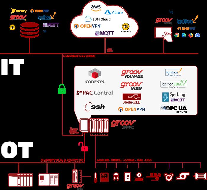
Identify how a specific connectivity solution offers specific technical benefits, and the potential impact on smart manufacturing operations.
Edge programmable industrial controllers
Hougland said that emerging edge programmable industrial controllers (EPICs) provide reliable and secure solutions for factory automation connectivity.
First, these EPICs enable users to monitor, control, and communicate with industrial equipment worldwide. Because they are designed to be compatible with a wide range of automation devices, users can quickly and securely connect to their machines and control them remotely. Their real-time data means users can make quick and informed decisions to optimize their production processes.
Second, the EPIC’s built-in HMI tool gives users the ability to create custom graphical
interfaces to visualize and control their equipment and receive alerts and notifications when something malfunctions.
Third, the EPIC’s security and communication features make it much easier to securely democratize operational technology data with business and cloud applications. EPICs are a powerful and cost-effective solution for industrial automation and connectivity.
“EPICs are versatile industrial automation devices that combine a powerful I/O system, a real-time industrial controller, numerous networking options, and comprehensive software options. This all-in-one solution streamlines industrial automation, providing control, data processing, and visualization in a single device,” Hougland added.
40 industrial ethernet book 03.2023
SOURCE: OPTO 22 Connected Factory
An EPIC's I/O system offers a wide range of analog, digital, and serial signals selected to suit specific applications. The system supports various fieldbus protocols, enabling it to communicate with other devices on the factory floor. The EPIC is programmed using familiar automation languages. It can also run user-developed code on an open-source Linux operating system, supporting several programming languages, including Python and Java, making it easy for developers to create custom applications. The software platform includes a web-based HMI for real-time visualization, data logging and analysis, dashboard creation, and remote access.
EPIC applications focus EPICs are used in various industrial applications, including manufacturing, pharmaceutical, food and beverage, oil and gas, and water/wastewater treatment, for monitoring, controlling, collecting data, and generating reports on production efficiency.
EPIC-based solutions contribute to IIoT and enterprise connectivity in many ways. For example, they typically have built-in OPC-UA drivers for Allen-Bradley, Siemens, and Modbus TCP systems, as well as MQTT with Sparkplug B. For enterprise connectivity, EPIC solutions provide simple logic flows using opensource Node-RED software, streamlining data processing and integration with web services and cloud platforms.
Hougland added that these new technologies are helping engineers deal with the challenges and complexities of implementing new connected systems.
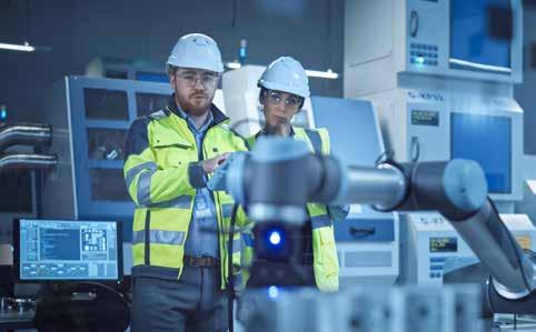
“Factory connectivity has seen significant advancements in recent years that address automation engineers’ challenges. One such challenge is integrating legacy equipment and systems into modern automation networks. Industrial gateways and edge computing devices bridge legacy systems and newer technologies, allowing for better data collection and communication among different devices and systems in the factory,” Hougland said.
Another challenge is the need for secure remote access to plant floor systems. EPICs provide secure remote access to plant floor devices through a virtual private network (VPN) and the MQTT protocol. The VPN provides a secure virtual tunnel for authenticated remote access to the plant floor equipment. MQTT reduces security concerns by using outbound, device-initiated communication.
“Cloud computing combined with edge computing provides centralized data management and analysis, offering valuable insights into factory operations. This combination helps automation engineers monitor and optimize processes, reduce downtime, and improve efficiency across the entire manufacturing organization,” Hougland added.
“Overall, these advances in factory connectivity have helped automation engineers address challenges related to legacy equipment integration, remote access, data management, and automation efficiency.”
Information-enabled smart devices
Smart devices enable comprehensive view of operations and use analytics.
According to Todd Bissell, Strategic Marketing Manager at Rockwell Automation, technology and product development are enabling new solutions for factory automation connectivity.
“Today’s smart manufacturing approach combines data and technology to achieve results. By leveraging information-enabled smart devices on the plant floor, manufacturers can get a comprehensive view of their operations and use analytics to get knowledge and insights that help optimize operations and drive Overall Equipment Effectiveness (OEE),” Bissell told IEB recently.
“While EtherNet/IP is the network of record, direct connection of field devices such as sensors, safety switches and signaling products to Ethernet is either physically difficult (due to small device size), overkill for the data being generated, or simply too costly for these simple devices. However, these devices generate the bulk of plant floor data. This is why several linking technologies have emerged that allow for low cost yet effective ways to unlock the information that has long been in these devices and deliver that data to where it can provide value.”
He said that some examples of enabling
technologies are:
• Hart for analog devices (for example: process instruments)
• IO-Link for discrete devices (for example: sensors)
• GuardLink® for safety devices
With an information-enabled connection to smart devices, manufacturers get a much more comprehensive view of their operations. The system can often detect issues before they become production issues. In a traditional control system, you would not know if, for example, a photoelectric sensor was too dirty to operate properly or if a safety switch was damaged. The issue wouldn’t be evident until a downtime event occurred and then, through extensive troubleshooting, was eventually tracked back to the faulty device. This wastes valuable time and production capability. IO-Link enabled sensors and GuardLink safety devices can provide data and diagnostics to the control system before production issues happen.
“Smart machines and equipment allow manufacturers to better leverage the most powerful element that too few organizations today are fully capitalizing on: their own real-time data,” Bissell said. “This intangible commodity is the key to better understanding operational performance at the most granular level so you can improve operations and produce more--at higher-quality levels--in a more efficient manner.”
Connectivity solutions
He also said that, while employing smart technologies throughout the entire plant floor and enterprise might sound ideal, companies may want to start by addressing key areas
41 03.2023 industrial ethernet book Connected Factory
SOURCE: ISTOCK
"Today’s
smart manufacturing approach combines data and technology to achieve results. By leveraging information-enabled smart devices on the plant floor, manufacturers can get a comprehensive view of their operations and use analytics to get knowledge and insights that help optimize operations and drive Overall Equipment Effectiveness (OEE),” Todd Bissell, Strategic Marketing Manager, Rockwell Automation.
and critical processes that would lead to lost production time. Smart devices can be used in any application and industry, but especially in rugged industrial environments prone to device lifecycle and environmental effects. Ultimately, these device-level enabling technologies use adapters to deliver data from industrial control components into the Ethernet system without the overhead required for an end-to-end Ethernet solution. When looking from the outside in, the seamless integration of enabling technologies makes them transparent, basically a right-sized extension of an Ethernet network.
“Today’s unprecedented access to real-time data can be turned into actionable information, logged, and analyzed to help workers make better decisions and ultimately optimize not only equipment setup, maintenance, and troubleshooting, but the overall manufacturing process,” Bissell added.
“When connected via an open and standard network architecture, such as EtherNet/IP™, enabling technologies provide greater data sharing upstream and downstream, allowing for real-time collaboration across all levels of an organization’s enterprise from the plant floor to the front office. So, all the data harvested from smart devices can be used for changes to overall business processes down to device-level status messages that can be used to reduce downtime,” he said.
Fundamental building blocks
Enabling technology for AI and digital twin technology that can optimize and transform operations.
According to Jeff Winter, Director of Smart Manufacturing and IIoT Division for the International Society of Automation, factory connectivity solutions are integral to the ultimate goal of business transformation that Industry 4.0 is all about.

“Connectivity is just the starting point. It’s important to look beyond connectivity and begin by considering the business outcome you’re trying to achieve with connectivity. Organizations can use a tool like the Acatech Industry 4.0 Maturity Index to assess their level of digital maturity on a scale of 1-6. According to their 2020 survey, 80 percent of companies still fell at level two connectivity,” Winter told IEB recently. “Unfortunately, connectivity alone doesn’t get you much and is often hard to see an ROI. It is, however, a fundamental building block that enables all the really cool technologies (i.e. artificial intelligence and digital twins) that can optimize and transform operations. Evaluating what the end goal is for your automated environment will help highlight solutions that can help you go beyond simply factory connectivity.”
Common data model
Winter said that the most powerful thing a company can do is develop a common data model that provides a consistent framework for organizing data, defining relationships between data entities, and mapping data to a common language. This is especially important when companies are trying to address IT/OT convergence, because operational technology (OT) and informational technology (IT) have different protocols, architectures and technologies, as well as teams with different goals, priorities and perspectives.
“Having your IT and OT environments connected is one thing, but having the data from those systems properly contextualized, normalized and indexed…that’s a whole other ballgame, and where the real transformation takes place. Without a common data model, you could be flooding databases with different data types and values that other systems can’t understand.”
By developing a common data model across environments, the connected systems can now not only access each other, but also understand what the other is doing because they share the same language. ISA-95, a standard developed by the International Society of Automation, provides a great
starting point for developing that data model by defining a set of interfaces and information models for each level of abstraction, allowing for interoperability between systems at different levels. This enables companies to create a seamless flow of information and control across the manufacturing process.
Applications viewpoint
Winter said that one of the biggest impacts of factory automation connectivity is the ability to capture data that can be used to inform operations and proactively address production with predictive analytics. The idea is that you can’t do predictive analytics without collecting data. You can’t collect data without connectivity.
“Factory automation connectivity is the first step to greater enterprise connectivity, and the ability to have real-time information at your fingertips from everywhere. The application of connectivity is so crucial that it’s why, according to a 2021 report from IoT Analytics, the number one use-case for smart operations is remote asset monitoring,” Winter said.
This monitoring can be used, for example, to create real-time factory control towers. Imagine having a real-time dashboard to share
42 industrial ethernet book 03.2023 Connected Factory
SOURCE: ISTOCK
"Factory automation connectivity is the first step to greater enterprise connectivity, and the ability to have real-time information at your fingertips from everywhere. The application of connectivity is so crucial that it’s why, according to a report from IoT Analytics, the number one use-case for smart operations is remote asset monitoring,” Jeff Winter, Director of Smart Manufacturing and IIoT Division for the International Society of Automation.
with your COO that show’s your company's overall equipment effectiveness (OEE). Double click and it can drill down and provide the OEE for every facility, production line or even individual machine. This type of visibility can have a massive impact on the ability to do production planning and production optimization. Add AI and machine learning to this level of reporting and you have the power to not only remotely monitor but perform predictive analytics.
Engineering challenges
Winter said that some of the biggest challenges for automation engineers are issues of common language and overall ownership of architecture. The question of selection of architecture – including platforms, devices, protocols and everything related – often doesn’t have a clear owner. Should operations teams manage it? IT? The internal fighting over architecture, technologies, implementation, and governance can slow down or even completely stall Industry 4.0 initiatives by never getting the proper connectivity foundations put in place.
Expanded digital capabilities
Variable Frequency Drives implement
connectivity options along with integration of sensors and other devices.
According to Jon Mosterd, Manager, North America Center of Excellence (Applications) for Danfoss Drives, technology developments are enabling new solutions for factory automation connectivity.
“Increased digital capabilities on Variable Frequency Drives (VFD) are allowing for
more onboard connectivity and expanded functionality. With a variety of options, you not only can easily integrate the drive into an automation system, but you can also integrate sensors or command ancillary devices, such as a valve or damper, without having to add extra controllers,” Mosterd told IEB recently. “Not only does the drive provide a power supply for these devices, but it can also have built-in capabilities to monitor them, perform a logic function, and then send signals to operate other devices nearby.”
He said that these benefits are compounded when we consider options for remote monitoring or cloud-based data gathering. These can enable operators to monitor systems in a central location for easier maintenance and service dispatching, especially in locations with limited personnel present to regularly monitor system performance. Growing data and interconnection options in a VFD are allowing automation to not only save energy on a process, but also perform many different functions without having to add more hardware or network points.
Impact on smart manufacturing
Traditionally, VFD’s have been utilized for their power conversion capabilities to vary motor speed and reduce energy consumption. With the growth in embedded digital tools, the ability to integrate external sensors and control other components, VFD’s are changing how automation teams are utilizing them.
An example of this is with integrated predictive maintenance as part of a VFD that allows smart manufacturing to better operate equipment and assess its current condition. Purchasing a VFD with conditionbased monitoring functions enables users to
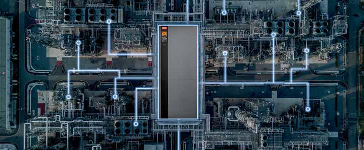
gather data about the health of their system. The algorithms utilized to perform this are embedded in the controls of the VFD and do not require any additional hardware. Alongside this, VFD’s are equipped with more internal sensors to better assess their own operating status. The data gathered can alert users of potential problems like overloading or maintenance concerns like the need to clean the air channel.
Additional capabilities for handling external sensors to monitor pressure, flow or vibration help provide the VFD with information to assess the system status. Collectively, this is all integrated into a single data point which helps to reduce installation costs, simplifies the solution, and can provide information to system operators to make better assessments on the health of their equipment. These units can even be setup to handle maintenance reminders based on run time or send warnings of potential problems.
"Predictive maintenance and conditioned based monitoring integrated into a single component are unlocking new access to tools with reduced costs of implementation. Often, these features have not been utilized due to complexity, cost or space constraints as they required additional hardware,” Mosterd said. “Upfront, these new tools are providing cost effective and easier installation. Instead of having one system to monitor vibration, another for motor winding integrity, and maybe another monitoring load or pressure, all of these items can now be delivered as part of a single VFD package. This reduces footprint, wiring and sometimes even the need for additional power supplies and fusing.”
“When integrated into an automation system you only need to have a single communication
43 03.2023 industrial ethernet book Connected Factory
SOURCE: DANFOSS
“Increased digital capabilities on Variable Frequency Drives (VFD) are allowing for more onboard connectivity and expanded functionality. With a variety of options, you not only can easily integrate the drive into an automation system, but you can also integrate sensors or command ancillary devices, such as a valve or damper, without having to add extra controllers,” Jon Mosterd, Manager, North America Center of Excellence, Danfoss Drives.
cable with a single network item added into your control system. This reduces complexity and the amount of system integration. In fact, the VFD’s digital tools and algorithms will handle certain functions and alerts internally which could then mean less code for a programmer to have to include in their system. Further, this technology can be delivered with the ability to turn on machine learning, such that it can gather unique data and set a framework that is best for the specific application. This reduces the complexity of having to take standard models and trying to make them work for your unique needs.”
Automation challenges
Mosterd said that one challenge that factory connectivity is helping to address is related to having skilled personnel on staff and readily available. With remote monitoring, integrated predictive maintenance and more digital capabilities, people are being enabled to do more with less. Consider a remote part of a facility, or maybe a pumping station that is some distance away and is infrequently checked. Increased digital options, more data and remote connectivity allow operators to automatically be alerted of an abnormality.
“Instead of dispatching someone to diagnose an issue, they can use more data to potentially identify the problem, make decisions on how critical it is and then dispatch someone with the correct tools and hardware. Alternatively, with more data they can typically reduce troubleshooting time by providing service teams with information on where the problem is occurring,” he said.
“Many VFD’s and other digital equipment also are delivered with onboard information explaining alarms or faults and potential solutions. This can have a large impact on runtime, reduce troubleshooting costs and even reduce the amount of labor associated with system inspections, maintenance, and monitoring. Ultimately this quickly enables automation engineers to develop solutions that have long term benefits for the facilities they are working in.”
Impact of SPE technology
Potential support for cloud connectivity and TSN in factory and process automation.
According to Phil Marshall, Chief Operating Officer at Hilscher North America, there are several technology trends currently impacting factory automation such as cloud connectivity via open platform communications unified architecture (OPC UA) or message queuing telemetry transport (MQTT), time-sensitive networks (TSN) and single pair Ethernet (SPE).
SPE can potentially support both cloud
"SPE is an excellent basis for handling wellestablished Industrial Ethernet protocols, such as PROFINET, Ethernet/IP and more. It provides an excellent platform for all the other major trends in automation.” The netX communication controller is intelligent technology for implementing all proven fieldbus and Real-Time Ethernet systems. Phil Marshall, Chief Operating Officer, Hilscher North America.
connectivity and TSN and may prove to have the greatest impact on factory and process automation.
Single Pair Ethernet

“SPE uses IP-based protocols at 10Mbit, 100Mbit and GBit speeds or higher. This technology is based on a two-wire cable, allowing it to utilize more compact connectors than those of classic Ethernet that typically uses up to eight wires with an RJ45 interface,” Marshall told IEB recently. “This design saves space by facilitating the use of more compact devices which will reduce system complexity and costs — especially in terms of installation and cabling. SPE cables can carry both data and power, enabling the network to power end-devices for even greater cost and space savings.”
Marshall said that SPE doesn’t need network gateways for deployment. The IP-based protocol enables SPE to support simpler vertical communications, allowing field level sensors to connect directly to the cloud when necessary. As a direct result, adding SPE-based sensors in brownfield applications and transferring information directly to the cloud will be easy. With a 10BaseT1L cable at 10 Mbit speeds, SPE can support networks up to 1,000 meters — a major benefit for huge production plants.
The Advanced Physical Layer (APL) is an enhanced version of SPE and it is used in process automation application environments that typically involve explosive atmospheres (Ex Zone 0-2). In these settings, powering via the network is highly beneficial.
As another advantage, both SPE and APL can reuse the existing cable infrastructures extensively employed throughout factory and process automation.
“Considering these benefits, this technology has the potential to combine all the latest
technological trends in automation, making SPE a win-win-win-win in all areas of automation,” Marshall said.
Industrial Ethernet ecosystem
SPE is an excellent basis for handling wellestablished Industrial Ethernet protocols, such as PROFINET, Ethernet/IP and more. It provides an excellent platform for all the other major trends in automation. Even in process automation — where HART and Foundation Fieldbus have a leading role — typical industrial protocols like PROFINET and EtherNet/IP are on the way with APL.
“APL is in the introductory phase in process automation with field device applications such as flow meters with PROFINET or Ethernet/IP via 10BASET1L cable,” Marshall said. “However, SPE for factory automation is in a much earlier phase of use. As an enabling company, Hilscher is following the trend closely. A media switch is already in the pre-launch phase to allow users to trial connectivity between SPE and industrial Ethernet networks.”
Currently, SPE mainly covers infrastructure products like 100 Mbit and RJ45 industrial Ethernet switches to either 100 MBit or 10 Mbit SPE networks. These devices primarily serve as a migration path, or for extensions in brownfield installations.
Early products are focused on short-term benefits like easier network expansion and reduced installation and cabling costs. But we expect more and more field devices to appear supporting SPE-based Industrial Ethernet protocols such as PROFINET, EtherNet/IP, Modbus/TCP and OPC/UA, which will help build common and seamless networks from the sensor level through the control level and to the cloud. The long-term benefit is closing the last communication mile for smart production that is fully digitalized, enabling more intelligent approaches to saving downtime, optimizing processes and increasing profitability.
Multiplicity of networks
Marshall said that, broadly speaking, the main connectivity challenge facing automation engineers today is the multiplicity of networks in factory automation.
Different technologies in terms of protocols, physical media and distributed intelligence must be combined to build a production plant. This complexity may become more severe when vertical communications to cloud or IT infrastructures are introduced. This inevitably results in higher installation, along with higher commissioning and maintenance costs.
“With SPE there is a chance to set up more homogenous and consistent networks. In essence, SPE represents a perfect platform for the seamless digitalization of smart production plants and processes,” Marshall said.
Al Presher, Editor, Industrial Ethernet Book.
44 industrial ethernet book 03.2023 Connected Factory
SOURCE: HILSCHER
Keep networks connected & protected
New Gigabit Ethernet switches simplify configuration with robust performance and security features.
N-TRON® SERIES NT5000 GIGABIT INDUSTRIAL switches from Red Lion set a new standard for performance, reliability and ease of use, with security features designed to keep networks connected and protected.
Innovative technologies empower industrial organizations to access, connect and visualize their data, including the N-Tron® Series NT5000 Gigabit Managed Layer 2 Ethernet switches.
As industries around the world digitally transform and optimize their operations, reliable and secure network access is absolutely critical. NT5000 switches and their gigabit speed are designed to improve network security and reliability for industrial organizations of all sizes and environments.
The NT5000 maximizes operating performance and system uptime through seamless integration, advanced management and diagnostic capabilities, network redundancy and layered security, and helps organizations meet information technology and operational technology needs for dependable communication.
“Clear, comprehensive and fast network management is essential for organizations to achieve maximum uptime,” said Diane Davis, director of product management, networking, at Red Lion.
“The NT5000’s simple graphical user
interface includes a logical view showing active ports, power supply, temperature and contact relay status of the switch and colorcoded gauges for port traffic and events to allow administrators to quickly identify and address possible network disruptions in real-time, helping lower total cost of ownership.”
Designed and assembled in the United States, NT5000 switches are available in 6, 8, 10, 16 and 18 port configurations in all copper or a mix of copper and fiber options that can meet specific installation requirements. With a durable, metal enclosure and wide temperature range, the NT5000 is a compact solution for reliable operation in harsh, industrial environments, including factory automation, robotics, food and beverage, oil and gas, marine and rail.
Streamlined setup
Configuring switches can be a confusing and time-consuming process. The NT5000 is engineered for fast and easy deployment right out of the box. Its modern, graphical user interface includes a configuration wizard that walks users through initial setup.
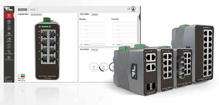
Layered security
Today’s cybersecurity threats can result in severe consequences. Not all switches
have the layered network security to help prevent unauthorized access. The NT5000 features password encryption, multilevel user access and MAC security, IEEE 802.1X with RADIUS remote authentication and more. Administrators can view the event and syslog to clearly see the state of the network in real time and receive notifications about access attempts or configuration changes. The switch can be set to automatically disable user or port credentials after failed access attempts.
Sophisticated diagnostics and management
The NT5000 also features: graphical dashboards; N-RingTM auto-member; port mirroring; cable diagnostics; STP/RSTP/MSTP; IGMP v1/v2/v3; SNMP v1/v2/v3; NTP, LLDP and LACP; along with fast boot allowing traffic to pass in less than 20 seconds
Wide shock and vibration tolerance
Extensive compliance certifications, including Product Safety: (UL/CUL) Ordinary and Hazardous locations, Emissions/Immunity: FCC/ICES/CE, ATEX/IECEx, Marine: ABS, Rail: EN 50155, EN 50121, EN 61373, UKCA. Red
45 03.2023 industrial ethernet book Connected Factory
Learn More
Lion
SOURCE: RED LION
AWS IoT Core launches location service powered by LoRa Cloud. Collaboration simplifies the creation of asset tracking solutions and easily connects LoRa Edge devices to AWS.
EtherNet/IP technology and applications update
EtherNet/IP offers a potent industrial automation network solution by relying on commercial-off-the-shelf technology and standard, unmodified Internet Protocol and Ethernet made up of IEEE 802.3 combined with the TCP/IP Suite, to enable seamless, interconnected networks for local, edge and cloud applications.
FACTORY CONNECTIVITY SOLUTIONS HAVE accelerated the transition from fieldbuses to Industrial Ethernet. And now, Single Pair Ethernet offers a new impetus for growth. For IEB's update on EtherNet/IP TM technology, the Industrial Ethernet Book reached out to Dr. Al Beydoun, ODVA President and Executive Director to offer his perspective on this key Industrial Ethernet technology.
What key technical trends are driving the adoption of EtherNet/IP automation, control and networking solutions?
Beydoun: The value of increased connectivity including easier commissioning, troubleshooting, and asset tracking driven by IIoT and Industry 4.0, have accelerated the transition from traditional fieldbus to industrial Ethernet. As companies digitalize in their journey to further optimize operations, EtherNet/IP is seeing sustained strong growth due to being a proven automation solution that is continuously enhanced to address future advancements in industrial control and communication. The ability for end users to now leverage edge and cloud analytics to gain insights into historical trends and make predictions about future device and production status has also increased the value of standardized Ethernet networks with robust
safety and security protocols like EtherNet/IP. EtherNet/IP is a proven industrial control networking solution that can accommodate everything from a single controller, machine, or skid to entire facility installations across discrete, hybrid, and process automation. Diverse industries such as automotive, semiconductor, packaging, food & beverage, pharmaceutical, water and wastewater, chemical, mining, oil & gas, and more rely on EtherNet/IP communication and control. EtherNet/IP utilizes ODVA’s CIPTM application layer and deploys it on standard networking technologies such as Ethernet, Single Pair Ethernet/Ethernet-APL, Wi-Fi, or 5G.
What are the key technical advantages of automation systems that utilize EtherNet/ IP technology solutions? What are its primary technology benefits for automation and control networking?
Beydoun: EtherNet/IP has become a leading industrial automation network solution in part by relying on commercial-off-the-shelf technology and standard, unmodified Internet Protocol and Ethernet made up of IEEE 802.3 combined with the TCP/IP Suite, which enables a more seamless, interconnected network for local, edge and cloud applications. Additionally, EtherNet/IP offers a complete
suite of network extensions for specialized applications including safety, security, energy, time synchronization, and motion. CIP Security offers a distinct advantage for EtherNet/IP given that it offers the flexibility of different levels of device level security depending on the network performance requirements relative to the sensitivity of the information and potential negative health and safety impacts of the intervention of a bad actor. CIP Security allows for end users to apply one or more protections as desired such as end point authentication, message encryption, user role protection, and more. EtherNet/ IP also offers network uptime redundancies that ensure a device failure won’t impact other devices with Device Level Ring (DLR).
Additionally, EtherNet/IP is lightweight enough to be able to work with resource constrained devices such as contactors and push buttons via Single Pair Ethernet (SPE). Finally, EtherNet/IP supports process automation via features such as NAMUR NE 107 device status and Ethernet-APL support for long reach and intrinsically safe applications.
What is the impact of SPE and/or Ethernet-APL technologies on the types of EtherNet/IP network architectures that are possible? What are the advantages of these new approaches?
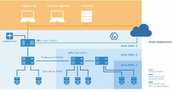
Beydoun: As a media independent network, EtherNet/IP is well positioned to take advantage of the benefits of Single Pair Ethernet (SPE) since it is just another physical layer. SPE allows for cost and size reductions in Ethernet PHYs, cable and connectors that enables cost effective connectivity for smaller devices as well as more efficient long cable runs. This opens up the possibility to connect simple devices to Ethernet that were previously only hardwired or controlled via fieldbus technology.
SPE also reduces the overall labor for
46 industrial ethernet book 03.2023 Connected Factory
The Ethernet-APL topology and architecture provides key benefits for new potential applications.
SOURCE: ODVA
panel installations and provides information for concepts such as prognostics. ODVA’s in-cabinet resource-constrained device solution is a case in point as it enables contactors and push buttons to be connected to EtherNet/IP via a SPE multidrop flat cable.
It's important to note that SPE encompasses 10BASE-T1L General Purpose SPE applications, 10BASE-T1S in-cabinet applications, and 10BASE-T1L Ethernet-APL applications. Furthermore, there are multiple IEEE SPE standards in addition those mentioned here, such 100BASE-T1 for automotive applications.
Ethernet-APL meets the ruggedness, simplicity, and security expected by the process industries for a control network. The Trunk and Spur topologies are familiar to end users and Ethernet-APL allows up to 1,000meter trunk lengths and 200-meter spur lengths.
Ethernet-APL leverages the same Type A fieldbus cable that is currently installed in process plants today. In fact, existing Type A cable may be reused if the cable integrity is verified and resistance standards of 100 ohms with +/- 20 ohms tolerances are met. Since it is just a physical layer, Ethernet-APL allows end users to access standard safety and security services built on IEC 61508 and ISA/IEC 62443 from the leading industrial automation standards bodies.
This includes CIP SafetyTM and CIP SecurityTM capabilities for EtherNet/IP. EtherNet/ IP is able to expand precise, efficient Ethernet-based control and commissioning across process field instrumentation via the Ethernet-APL physical layer. The full use of EtherNet/IP in process automation enables concurrent seamless connectivity from the field devices to the controllers, to Industrial IoT applications, as well as the edge and cloud for prognostic analysis.
What are specific application areas that the newest EtherNet/IP solutions targeting? How are these solutions contributing to IoT and enterprise connectivity?
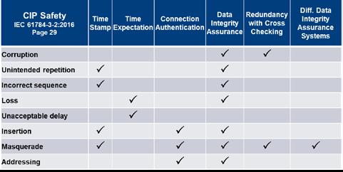
Beydoun: The newest application areas that EtherNet/IP solutions are targeting include flexible assembly lines enabled by wireless AGVs, long cable runs in warehouses and in-cabinet wiring using Single Pair Ethernet (SPE), and the addition of different types of traffic to OT networks such as vision and surveillance cameras that can benefit from Time Sensitive Networking (TSN). EtherNet/ IP is network technology independent as a result of using CIP at the application layer. This allows for wireless support via Wi-Fi, 5G, and Bluetooth among other technologies that can power AGVs, end of arm tooling for robots, and other mobile devices in a plant. Wireless support for Private 5G has recently been proven in a joint test bed with Rockwell Automation, Ericsson, Qualcomm, and Verizon. Additionally, CIP Safety can be run over wireless due to relying on the black channel principle that leverages data validation techniques built into the network extension.
The media independence of EtherNet/IP also contributes to support for IEEE 10BASE-T1L/ T1S SPE, which is growing in importance due to enabling the benefits of Ethernet connectivity at a low cost to devices such as in cabinet contactors and push buttons, discrete RFID sensors, and process temperature, level, and flow sensors. SPE is also capable of long cable runs of up to 1,000 meters for large plants such as package sorting facilities and chemical refineries.
60802 TSN will make it possible to add new devices to existing networks years after initial commissioning and to include new types of devices on OT networks such as cameras for machine vision and surveillance without significantly degrading network reliability. Once the IEC/IEEE 60802 standard is published, a new Common Industrial Profile (CIP) Application Profile will be released to make 60802-enabled TSN an option for new EtherNet/IP devices either natively or via a gateway. Existing EtherNet/IP devices can also work on TSN networks, although their Quality of Service on the wire may be degraded when
compared to a non-TSN network. 60802 TSN will be able to align with CIP Motion via a motion control planner using a common notion of time. Once CIP Motion and IEC/IEEE 60802 are aligned, network transport can be facilitated using scheduling as necessary to meet the needs of the network and coexist fairly with existing traffic. EtherNet/IP is anticipated to have an 60802 TSN compatible specification available as soon as is practical after the IEC/IEEE 60802 TSN specification is released.
What are the engineering challenges that the newest EtherNet/IP systems and architectures are designed to address, and how is EtherNet/IP evolving to provide more comprehensive solutions?
Beydoun: EtherNet/IP systems and architectures are now able to offer Ethernet-APL devices, which unlocks the advantages of commercially based industrial control hardware, an object-oriented foundation, and standard internet protocol compatibility including TCP/IP, HTTP, FTP, SNMP, and DHCP within the process industries.
ODVA is also continuing to expand the EtherNet/IP ecosystem with the next generation of digitized device description files, including FDT, FDI, and xDS, to simplify integration into asset management tools. The end goals of the device description efforts are to provide a standard, robust and detailed description of device information, implement secure device description artifacts, and prepare for a future driven by Industry 4.0 and IIoT.
Furthermore, ODVA supports the PA-DIM process automation device information model specification that can be integrated across communication protocols, meets the requirements of the NAMUR Open Architecture (NOA), and enables end users to better use device data from across the plant.
Future plans include a partnership between ODVA, OPC Foundation, PI, and VDMA to develop a new interface standard for the acquisition of energy consumption data in industrial manufacturing to improve power consumption management. EtherNet/IP also plans to continue to evolve for future requirements by enabling reliable, secure communications between CIP-enabled industrial control system devices and the cloud as well as to enable common cloud gateway and device management tasks. One of the ways this will be accomplished is via a joint working group with the OPC Foundation to develop an OPC UA companion specification to the Common Industrial Protocol (CIP).
47 03.2023 industrial ethernet book Connected Factory
Learn More
Dr. Al Beydoun, President and Executive Director, ODVA.
CIP Safety Functionality and benefits.
Switches enable IT-OT convergence
New generation of Industrial Ethernet switches strengthens OT/IT collaboration.
THE INCREASING NETWORKING OF MACHINES, controls and IT systems in industrial plants leads to increasingly complex networks at the production level. To ensure reliable data exchange, high-performance Industrial Ethernet Switches with a high number of ports and data bandwidths are required.
Scalance XC-/XR-300 series
By using SCALANCE X-300 Ethernet switches as compact devices or as 19” rackmount switches, users can benefit from a high level of functionality and significant flexibility –and also from Time-Sensitive Networking (TSN) in the future.
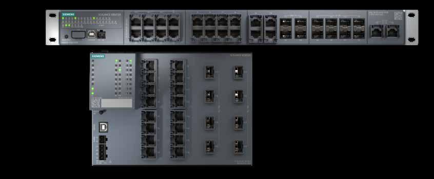
To this end, Siemens has renewed the Industrial Ethernet Switches of its Scalance XC-/XR-300 series and upgraded them with
additional functions for next-generation industrial networks. So-called managed Layer 2 switches from the Scalance X Industrial Ethernet Switch product family are now available – both as compact models and as 19-inch variants for control cabinets. The new switches thus replace the portfolio of the current Scalance X-300 series and carry the model designation Scalance XC-/XCM-300 in the compact version and Scalance XR-/ XRM-300 in the 19-inch version.
The new series have a high port density, which allows many devices to be connected within large network infrastructures. Thanks to their high-bandwidth ports (up to 10 Gbit/s), they enable various OT network applications for data, voice, video and Profinet.
Industrial companies also benefit from
a migration option to the new switch generation. This means that the changeover is possible for all models of the Scalance XC- or XR-300 series introduced from 2022 onwards with the long-standing operating system and Scalance XCM- or XRM-300 with the new operating system. The respective operating systems must be updated by software update. This means users don't have to replace devices to meet the latest requirements. In addition, software updates with the new operating system are to be implemented more quickly in the future.
"With the new Industrial Ethernet Switches from the Scalance X-300 series, users are making the networking of their industrial plants as future-proof as possible," said Jens Geider, Portfolio Owner for Scalance. In addition to the established basic functions, the models of the Scalance XCM-300 and Scalance XRM-300 series will in future feature technology innovations such as Time-Sensitive Networking (TSN), edge functionalities and seamless redundancy for increased real-time communication and safety.
"The collaboration of OT and IT in industrial plants is progressing at all network levels. With the Industrial Ethernet Switches, OT networks are easily connected to IT and thus enable more flexible production", Geider said. Network security is also ensured by integrated security functions such as SSH and SSL protocols to protect against unauthorized network access and configurations.

48 industrial ethernet book 03.2023 Connected Factory
Learn More
Siemens
The next generation of industrial networks combines OT and IT to make the shop floor more flexible and safer.
SOURCE: SIEMENS
SOURCE: SIEMENS
View video on YouTube: https://youtu.be/R7UPvaQp-7c.
Remote production management: anytime, anywhere.
The possibility of access to relevant data and use of a virtually unlimited remote management system from any place with Internet access is becoming indispensable for modern production management. High flexibility appears to be one of the best characteristics for the entire system as well.
IN THE CURRENT ERA OF INDUSTRY 4.0, WHERE the manufacturing process automation is faster than ever before, an automated production line is an essential part of any modern operation.
Sinema Remote Connect
Sinema Remote Connect is based on state-ofthe-art technology in the field of automation which enables remote access to machines and lines. Its unique characteristics provide not only significant time and cost savings, but also higher work efficiency, better data sharing, support for teamwork and increased production capacity, because thanks to the remote access the service technicians can eliminate difficulties faster and thus shorten the downtimes.
Automated operation requires perfect coordination – each motion has a clear
purpose, no delays are allowed. In order for everything to work with maximum reliability and without any errors, a quality control system is necessary, enabling both production line control and the possibility of connecting various sensors, peripherals, RFID, optical reading devices, etc. However, a bespoke production line means high acquisition costs, so it is desirable to use standardized automation equipment that can be adapted to the needs of the particular customer.
One of the standardized automation solutions can be Sinema Remote Connect together with some of its hardware elements as Industrial Security appliance Scalance S. The key characteristics of this solution is the possibility of maximum interconnection of all systems relevant to production while maintaining the security strategies for the separation of individual technologies as well
as easy remote access from virtually anywhere.
Solution utilization for automotive parts production
One of the companies that has deployed the Sinema Remote Connect remote management system in the Czech Republic and takes full advantage of all its benefits is the German company Witte Automotive, which operates production plants in Nejdek and Ostrov nad Ohrí and focuses on the production of components for passenger cars. Door locks, safety hooks, door handles, etc. come off their production lines every day. Due to the scope of the produced range, it is essential that the control system is flexible and can be quickly reconfigured remotely. Full standardization is another key requirement for the most efficient production of such a diverse range.
"Before we discovered Sinema Remote
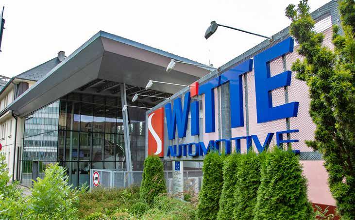
49 03.2023 industrial ethernet book
SOURCE: SIEMENS
Connected Factory
Witte Automotive focuses on the production of components for passenger cars. Door locks, safety hooks and door handles come off their production lines every day. Due to the scope of the produced range, it is essential that the control system is flexible and can be quickly reconfigured remotely.
Connect, we were dealing with quite a tough problem. We spent a lot of time looking for a way to connect machines and lines to higherlevel systems. We mainly needed them to be unified from the perspective of IP addresses and structure, while each behaving as a separate piece of equipment at the same time, with the possibility of remote control and maintenance. The system thus had to suit not only us, but also the requirements of the IT Department. We wanted the production lines to be mutually interconnected so that the higher-level systems could share necessary data with the production while maintaining remote management capabilities. The Sinema Remote Connect solution by Siemens, together with Scalance products, was the only one that enabled us to merge these requirements while at the same time meeting the security requirements defined by the IT Department. This is why we decided to deploy the solution not only in Nejdek, but also in Ostrov and in another factory in Ruse, Bulgaria.” explained Vít Stoklasa, Head of the Technical Department at Witte Automotive Nejdek.
Internal server management –higher cybersecurity
Companies with the size of Witte Automotive have to pay great attention to cybersecurity and the solution is ready for that. The heart of the system, the Sinema Remote Connect server itself, may be located directly at the customer’s manufacturing plant. However, it can also adapt to smaller production plants that do not require the own internal server management. Such plants may, for example, prefer the deployment of available cloud solutions, with virtually no changes to the
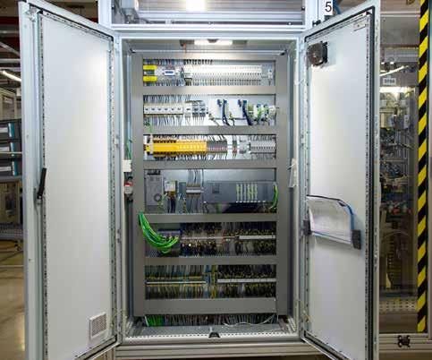
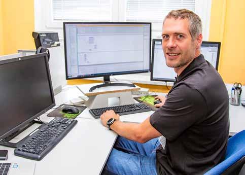
remote management solution itself. It does not matter where the Sinema Remote Connect server is actually located. What does matter is its availability.
”We had a different solution implemented in the past, but we did not want the remote management server to be located outside our company. And Siemens was the only of all potential vendors we found on the market who was able to meet this requirement. Thanks to
the current solution, we can have the remote management server and individual machines within the company fully isolated and run them entirely within our own network and under our own management. This means that all connections of all users to the machines and lines always pass through the Sinema Remote Connect server. Individual machines and lines are located behind hardware firewalls, so we comply with the Siemens’ recommendation regarding cybersecurity assurance through the separation of individual production lines. Each production line has its own Industrial Security Appliance Scalance S firewall. Furthermore, complete management of users of all machines and lines is under our control so we can see in real time who is accessing what machine when. All data is logged and can be retrieved at any time. We do not use any third-party data center or cloud solution”, Stoklasa said.
Prevention of unauthorized access
The main advantages of the Sinema Remote Connect solution include its versatility and also the fact that the remote management system uses the proven OpenVPN technical standard. Basic properties of the solution include the possibility of highly convenient setup of access permissions to individual pieces of equipment.
Users can only access the places they actually need for their work, they can't connect anywhere else. This type of security eliminates potentially hazardous situations caused by unauthorized access, efficiently protects the machines and contributes to significant
50 industrial ethernet book 03.2023
Vít Stoklasa, Head of Technical Department at Witte Automotive Nejdek, sets access permissions through Sinema Remote Connect.
SOURCE: SIEMENS
Connected Factory
Switchboard with connected Scalance S615 for higher cybersecurity for each production line.
SOURCE: SIEMENS
cost savings. Many production plants also require use of the same IP address range for all production lines. This important system property represents another benefit of the solution – it saves the IP addresses as it allows access even to systems with non-unique IP addresses. The system can also assign remote access options with different authorizations to different parts of the production line. This again contributes to higher security.
"We have connected all our lines to Sinema Remote Connect and so far we have not found anything that would not be compatible with the system. It was possible to connect even older lines without having to change the default router gateway settings. Sometimes we had problems with old cameras because it was not possible to input an IP address directly and search was disabled for security reasons, but that’s history and today’s systems already support this technology." adds Mr. Stoklasa.
Remote control anytime, anywhere
High flexibility appears to be one of the best characteristics of the entire system. The possibility of access to relevant data and use of a virtually unlimited remote management system from any place with Internet access is becoming indispensable for modern production management.
Remote control is available for all production technologies across all production plants of the parent company and its subsidiaries. Different access permissions can be set for individual systems, so that not only employees, but also suppliers and partners can benefit from remote access. The entire communication and production process thus again becomes more efficient and possible malfunctions in production can be eliminated in a very short time.
"During the pandemic, we used the remote management system on a daily basis, not only for the lines but for instance also for testing new jigs. The system does not have high hardware demands, one can control it from a home computer without any problems. Sufficiently fast Internet connectivity is enough. It can also be accessed from a tablet or mobile phone, for which the same access permissions apply as if the user were accessing from their computer at the production plant. In this way, it is possible to remotely access not only the control systems but also the camera sensors as well as the web servers of individual components and thus make their settings. Another great advantage consists in remote IP address assignment to Profinet devices using the DCP discovery functionality”, explained Stoklasa.
Fast service
Technical complexity of the entire solution often requires fast action of a service technician. Often there is no need to wait for
the technician to arrive in person, professional intervention into the system through a remote connection can be sufficient, which significantly saves costs and time. Sinema Remote Connect enables efficient and fast remote connection to machines and lines for the end customer’s service technicians, as well as for the technicians of the supplier or partner.

Future expansion of the solution
The cooperation between Witte Automotive and Siemens has lasted for many years and has worked so well that the parent company is considering its extension to its German operations also.
”Our company has recently moved to the latest version of Sinema Remote Connect server V3, which offers a number of new functions. Everything could be smoothly completed thanks to the help of colleagues from Siemens in Prague, who prepared everything for the migration and helped with all the theoretical pitfalls. The system is now fully up-to-date and at the same time meets the requirements of our IT colleagues. Of course, we expect
further extensions in the future, but at the moment it is more important for us that the system works properly wherever it is deployed and allows remote access from any location.” Stoklasa said about further plans regarding future cooperation with Siemens.
Highlights of the solution
• Considerable time savings and higher efficiency of production
• Reduced costs through elimination of production downtimes
• Faster and more precise decision making
• Better collaboration between teams
• Saving of IP ranges
• Ultimate security and technological standards
• Convenient and secure access to the system anytime, anywhere
• Easy expansion and repeatability at other sites
51 03.2023 industrial ethernet book
Vladimír Ševcík, Product Manager and Tomáš Skocil, Product Specialist, Siemens.
Visit Website
For larger machines customers use the more powerful Industrial Security Appliance Scalance SC646-2C .
Connected
SOURCE: SIEMENS
Factory
EtherCAT measurement terminals for wind farm monitoring
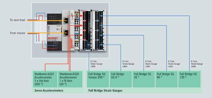
Accurate and fast data are crucial for the essential synchronization in wind farms. Continuously monitoring the turbine, blades and foundation performance support decision-making on planned maintenance and design validations and can help to avoid unplanned shut down periods or costly repairs in the event of failure.
THE UK AIMS TO BUILD ENOUGH WIND FARMS to power every household by 2030. The potential of wind power was demonstrated by a recent record, when on a single day in January wind farms produced 19,835 megawatts, which is enough to cover more than half of England’s electricity needs. The increased investment in renewable energy will be essential to hit the 2050 goal of Net Zero. Pulse Structural Monitoring Ltd, an Acteon company, have been tasked with monitoring selected turbine foundations in new wind farms, the solution is delivered by using Beckhoff technology and EtherCAT measurement terminals in particular throughout the design.
According to Pulse, the UK has become a world leader in offshore wind energy, with more capacity installed than any other country. However, offshore wind farms present difficulties due to the environment, making continuous monitoring of the whole turbine essential. By continuously monitoring the turbine, blades, and foundation performance, you can support decision making on planned maintenance and design validations for example, which in turn can help to avoid unplanned shut down periods or making costly repairs in the event of failure.
Measurement terminals in harsh environments
Environmental and operational loadings on the turbine affect all parts of the dynamically loaded structure. Part of the foundation’s role is to support the wind turbine generator load, provide stability and absorb additional loadings. The structural health of the foundation, which is considered as the top of the tower downwards, is critical to the performance and support of the WTG’s performance.
Structural Health Monitoring (SHM) systems for offshore wind turbine structures monitor a combination of corrosion and dynamic fatigue stress. Corrosion monitoring although an important parameter to be measured, due to the nature is less time critical. In contrast fatigue and modal properties monitoring are among the most important SHM techniques for wind turbine structures.
Pulse Structural Monitoring are delivering foundation SHM systems for clients in the renewables industry across the world using Beckhoff technology. Utilising Beckhoff’s broad range of I/O terminals for sensor integration allows Pulse to ensure time stamped data acquisition throughout the
structure. Pulse use the ELM370x module, which is an analogue input terminal from the EtherCAT measurement range. Due to the high sensitivity and measurement ability of these ELM modules, they are often used within labs but can also be integrated into industrial environments. This terminal can be set to over 30 different types of electrical signal, which makes it an exceptionally flexible measurement module for a range of sensors. To accurately determine the structural integrity throughout the full height of the structure, helping to ensure turbine operational efficiencies, the tower itself requires measurement points on four levels. This means that the I/O needs to be distributed, to have accelerometers and full bridge strain gauges terminated close to where they are positioned. Each level, on this top section, demands two ELM3704 modules for the varied signals, an EK1100 EtherCAT Coupler for communication and a power supply PS1011. These are fully enclosed and magnetically attached to the tower wall at defined heights giving accurate data capture across the tower.
For temperature, Pulse use the standard EL3202 terminal, a Beckhoff analogue input RTD EtherCAT terminal which provides data to allow for compensation algorithms to operate.
52 industrial ethernet book 03.2023
Technology
SOURCE: PULSE
Decentralized data acquisition system for the four upper tower levels, consisting of two ELM3704 EtherCAT Terminals, an EK1100 EtherCAT Coupler and a power supply PS1011. Picture: © Pulse.
The use of EtherCAT and its Distributed Clocks on the wind turbine’s foundation shows Pulse’s dedication to highly accurate monitoring and with this the ability to synchronise data. This synchronisation is key to the critical analysis of the overall structure, taking data from high precision accelerometers, strain gauges and temperature sensors located along the length of the structure, from top of the tower to the foot of the monopile with the exact timing.
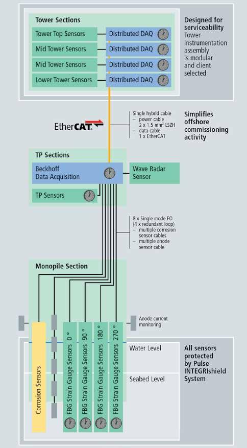
Synchronized data communication
Pulse have adopted the EtherCAT fieldbus and deploys this technology with the added benefit of power and communication through a single cable. EtherCAT P and EtherCAT/ Ethernet with power (ENP) helps circumvent the common difficulty of getting power to the sensors and distributed I/O at the top of the tower. The EtherCAT P and ENP system can run power and communications through a single cable and daisy-chain the fieldbus throughout the structure. Pulse have even taken it a step further by becoming a member of the EtherCAT Technology Group to develop their own subsea data hub and motion monitoring EtherCAT products called INTEGRIpod-NX2.
“The most important thing in our industry is data,” explained Stephen Harford, solutions architect at Pulse Structural Monitoring. “EtherCAT is already fast, which is essential for synchronization and getting the data we need. But EtherCAT with distributed clocks at every level allows us to take it one step further and keep full synchronization. With Beckhoff the quality of the technology is always guaranteed.”
From Harford's point of view, partnership is also important: “Beckhoff have also made every effort to help us keep to the tight schedule that wind farms have. They have supported us at every stage, coming down to train us when we could not make it due to our tight schedule. This is why we’re happy to successfully partner with Beckhoff on other projects we have.”
Data management with TwinCAT
All the data from the sensors is centralised and collected in a Beckhoff embedded controller, the CX2062 Embedded PC with TwinCAT PLC (TC1200) and Windows 10 IoT in this case. The CX2062 was chosen for its flexibility in expanding memory, increasing interfaces and processing power to run the TwinCAT runtime software plus the data management and processing application developed by Pulse. Beckhoff provides a free and open DLL to access all real-time data within the TwinCAT system via ADS. This open platform allows Pulse to both analyse data and send it directly to the higher level Scada system, providing key insight to the turbine’s health.
“What’s been great about this project,” explained Beth Ragdale, product manager
with Beckhoff UK, “is how we can utilize our previous work in the renewables sector to provide Pulse with our expertise in this area. We’ve also managed to provide everything from standard I/O terminals to high accuracy measurement modules, and, with a hybrid of power and communication in a combined cable
assisting Pulse to simplify their installations. That’s why we’re excited for the future projects we have together.”
Technology article by Beckhoff Automation.
Visit Website
53 03.2023 industrial ethernet book
Technology SOURCE: PULSE
Basic structure of the monitoring system implemented by Pulse Picture: © Pulse
Vision-guided robots: cameras give robots human-like functions
As with a machine vision system on an assembly line, a vision-guided robot uses intelligent processing to give it instructions. A slight alteration to the code allows the same robot to perform entirely different tasks, i.e., switching between products and batch runs, with no mechanical adjustments.
GENERAL MOTORS INCORPORATED THE WORLD’S first robots into an assembly process back in 1962. Although primitive by today’s standards, these robots opened new possibilities by performing dull, repetitive tasks automatically and more accurately than humans.
Reducing workplace danger was another benefit for GM. For instance, large car parts previously requiring multiple workers to lift into place could be hoisted up by a single robot, increasing safety along with productivity.
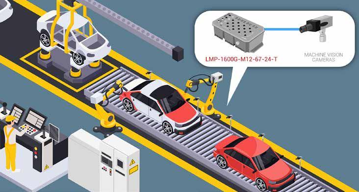
Emergence of vision-guided robots
At about the same time another industrial revolution was emerging — machine vision. Consisting originally of low-resolution monochrome analog cameras strung together with coaxial cables, machine vision systems quickly evolved to tackle complex inspection tasks such as edge detection, Optical Character Recognition (OCR), presence detection, and segmentation with far more precision than the human eye.
It was only a matter of time before these two technologies merged. The first VisionGuided Robot (VGR) was a pick-and-place machine known as the programmable transfer machine. Essentially, the machine had a monochrome camera that was programmed with an algorithm that took pictures of each workpiece that it interacted with. If the piece did not match the algorithm, the piece was rejected -- the programmable transfer machine would not interact with it.
Today, VGR technology has grown far beyond the programmable transfer machine due to advances in 2D and 3D cameras, visual servo control, embedded Ethernet networks, and increasingly more sophisticated software including AI. Advances in RGBD cameras — composed of a standard RGB camera and a depth sensor — have received considerable attention lately because of their ability to quickly acquire 3D models of the environment and to estimate the camera pose in a low-cost way. Prior to RGBD cameras, other approaches to SLAM (Simultaneous Localization and
Mapping) robotics relied upon laser sensors that are far more expensive.
Benefits of incorporating a vision system into an industrial robot are numerous. Empowering a robot to “see” allows it to precisely and consistently differentiate, pick, sort, move, weld or assemble various parts no matter their complexity. For instance, a multiple-step manual welding task on an automobile assembly line might take ten “blind” robots to perform since each part must be mounted in place before every weld. However, this same multi-step welding process can be done with a single VGR, since its camera can precisely align the different parts in place without human assistance.
Flexibility is another huge benefit of VGRs. As with a machine vision system on an assembly line, a VGR uses intelligent processing to give it instructions. A slight alteration to the code allows the same robot to perform entirely different tasks, i.e., switching between products and batch runs, with no mechanical adjustments.
54 industrial ethernet book 03.2023 Technology
SOURCE: ANTAIRA
Machine Vision is becoming much more critical in automation applications, especially where robotics is involved. GigE Vision is a global standard communication protocol that has been adopted by machine vision camera manufacturers
And then there is safety. With VGRs, factories can significantly reduce the risk of on-site accidents. To give you an idea of how that might work, consider a vision-guided forklift inside a warehouse. The automated forklift will sense obstructions along its pre-programmed paths and its movements to avoid contact with people or objects while precisely selecting items off pallets to meet customer orders. At Amazon, for instance, robotic material handling “co-bots” (collaborative robots) safely work directly alongside humans. The Amazon Sparrow robot uses vision and a robotic arm is able to pick up a new item and deposit it on a metal chute every three seconds, handling more than 1,000 items per hour.
The need for Ethernet switches
To add vision to a robot, one or more cameras are needed. One is mounted on the robotic arm, serving as the machine’s eye Other cameras are installed in strategic locations in the working cell to capture more visual data. Adding these static cameras will compensate for the limitations of the arm-mounted camera. Careful attention must be given to ensure the camera and lens has the proper resolution, frame rate, and depth-of-field required for the application at an acceptable cost. Low-cost
GigE Vision cameras are preferred since they use standardized, off-the-shelf Ethernet cables and components, while eliminating the need for frame grabbers.
All this engineering takes a collaborative effort on the part of vision systems providers, robotic arm manufacturers, and robotic systems integrators. It isn’t a surprise that a major trend today is to purchase VGRs already equipped with a vision system supplied by the robot manufacturer. This translates into faster adaptation into a production line, lower costs, and more responsive technical support from a single manufacturer.
Whether the vision system is installed by the end-user or the OEM, it will require an industrial Ethernet switch to create an embedded Ethernet network within the robot. Ethernet allows the individual robot parts to communicate with each other and is suitable for VGRs because Ethernet can handle image data.
At Antaira, we manufacture managed and unmanaged high port-count Industrial Gigabit Ethernet switches for robots that make the networking of Ethernet nodes uncomplicated, even simple. Our industrial switches can be found today in robots and co-bots used in agriculture, material handling, auto manufacturing and other sectors.
Antaira Ethernet switches
Space inside a robot is always a limiting factor. Luckily, the compact DIN-rail design of Antaira Ethernet switches allows them to fit easily next to a power supply, contactor, or relay. Power over Ethernet (PoE, PoE+, PoE++) is available on most of Antaira's industrial switches to uncomplicate the connection of cameras and other components. In addition to multiple Gigabit Ethernet ports, Antaira’s industrial switches also offer SFP slots for fiber optic connections. Fiber is impervious to electronic noise, so the SFP slots may be useful in running long-distance communications between the robot and a remote higher-level controller. While the industrial switch’s remaining Ethernet ports are able to collect data from various components in the robotic cell.
Antaira Ethernet switches are built industrialgrade to withstand harsh manufacturing environments. Antaira’s industrial switches are housed in sturdy IP30-rated metal cases and can be trusted to handle high levels of vibration, electronic interference, and wide temperature swings.

55 03.2023 industrial ethernet book Technology
Visit Website SOURCE: ANTAIRA
Henry Martel, Field Application Engineer, Antaira Technologies.
Antaira PoE M12 10 Gigabit fiber Ethernet switches are IP67 rated for harsh industrial environments including resistance to moisture, dust, vibration and shock.
Energy management and demand monitoring generates savings
Analyzing peaks in power consumption allowed confectionery manufacturer to optimize energy use throughout the entire manufacturing process. Visualization, monitoring and management of plant utilities result in savings of nearly EUR 70,000 over five years.
FAMIEL CONFECTIONERY CO., LTD., A confectionery manufacturer in Japan, has implemented energy management and demand monitoring at its main factory after introducing Mitsubishi Electric's energy saving data collection server "EcoWebServerIII". In addition to allowing Famiel to lower the contracted power supply level, the expansion of energy saving activities through real time visualization of electricity, gas, and water consumption led to a significant reduction of the overall utility costs – a total of some 10 million yen (approximately EUR 70,000 with exchange rate at 0.00696) over 5 years
System analysis
Analyzing peaks in power consumption allowed the factory to optimize energy use throughout the entire manufacturing process. Due to the
reduction in electricity demand, the factory was able to lower its contract power supply level.
The total cost for utilities was able to be lowered by visualizing the consumption of all resources: electricity, water and gas.
Founded in 1976 as a commercial frozen cake manufacturer based in Yokohama, Japan, Famiel Confectionery manufactures and sells cakes and other western confectionery. In addition to cakes sold under its own brand, the company makes a variety of frozen cakes at its factory and sells them to hotels and restaurants nationwide in Japan. In 2017, the company moved to Yokosuka, a city within the same Kanagawa Prefecture, where the current headquarters factory is located and this location became the hub for its business expansion.
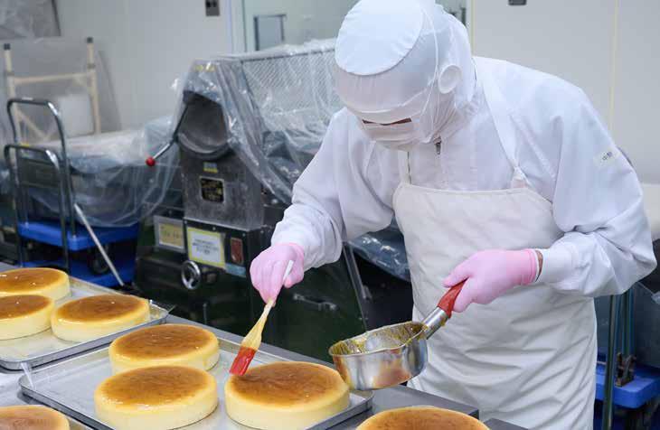
Cake manufacturing uses a large amount of electricity for the ovens to bake the cakes. “The three ovens in our factory account for about a quarter of the overall electricity we use. Power consumption reaches its peak when these ovens are all turned on, and our contract power is determined based on this peak,” says Hideyuki Moriya, General Manager of the Production Department. Therefore, since 2015, when the headquarters was located in Yokohama, the company has been working on visualizing power consumption by installing Mitsubishi Electric's "EcoMonitor" energy measurement units on ovens and other key equipment.
“When we visualized our energy consumption, I was able to understand many things, not only about how much electricity the ovens were using, but I also learned that
56 industrial ethernet book 03.2023
Applications SOURCE:
Famiel Confectionery sells a variety of cakes to hotels and restaurants nationwide in Japan. Photo shows the process of spreading jam on baked cheesecakes.
MITSUBISHI
the machine we use to wrap the cake in film did not use as much electricity as I originally thought it would. When such data was made available to the factory floor, it attracted the interest of our workers and made them think about how they could save more energy,” says Hideyuki Moriya. Therefore, when Famiel moved their factory to the current location in 2017, they not only reinstalled the visualization system, but also expanded the number of items for which they measured the energy use. They
also utilized “EcoWebServerIII”, an energy saving data collection server, and introduced energy demand monitoring and management throughout the factory.
“Confident about the ROI”
In the new factory, Famiel more than doubled the number of machines they monitored and decided to additionally measure the electricity used for air conditioning, as well as how much water and gas the factory consumed.
Explaining this decision, Hideyuki Moriya said, “In addition to the cost needed to reinstall the system from the old factory, we had to invest nearly twice as much to upgrade the system. I was, however, quite confident that we would be able to get a return on investment (ROI) since we had already saved more than we spent for our initial investment.”
The energy demand monitoring system for the new factory visualizes how much energy each item or air conditioner consumes. The key feature of this system is that it issues alerts in three stages according to the level of demand to prevent total consumption from exceeding the contracted power level. If an alert is issued at the third stage, which means demand is nearing the limit, their staff on site will turn off some machines to keep the demand within the limit.
Furthermore, to automatically control the air conditioning system based on the energy demand, Famiel linked the air conditioning system to the energy demand monitoring system via Mitsubishi Electric's integrated air conditioning management interface "AE-200J".
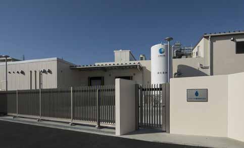
“I adjust the settings according to the season and the weather. We cannot get the full effect with the same settings all year round. To save energy, it is necessary to make full use of the system we have,” says Hideyuki Moriya.
In addition to efficiently controlling the energy demand at the new factory, Famiel
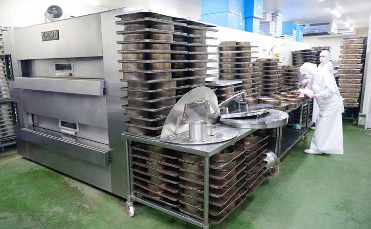
57 03.2023 industrial ethernet book Applications 57
SOURCE: MITSUBISHI
In the cake manufacturing process, ovens that bake cakes consume a large amount of electricity.
SOURCE: MITSUBISHI
In 2017, the company moved to Yokosuka, Kanagawa Prefecture, where the current headquarters factory is located.
Confectionery is also promoting activities to reduce demand over the long term with their main focus being the ovens. At the factory, electricity demand spikes when the three ovens are turned on at the start of work in the morning. The ovens continue to run after that, but once they are warmed up, they use less power for continuous operation. The key point in lowering the demand was to suppress the peak in demand right after the starting of the ovens.
The contract power level is determined based on the demand measured within each 30-minute period, so if Famiel wanted to lower the contract power, they had to make sure power consumption did not concentrate in one of these periods. Therefore, Famiel Confectionery changed the sequence in which they turn on the three ovens so that, instead of turning them on all at once, they decided to turn on the second oven 30 minutes after the first, and the third oven 30 minutes after that.
“After we start heating the first oven, it takes about 30 minutes to reach the required temperature. The change in the baking process therefore had a great impact on the preceding and succeeding processes, so we had to adjust each process, including how we prepare the cake dough. However, the significant fact was that the total daily working hours did not change.,” explained Hideyuki Moriya.
By optimizing the processes based on data from the demand monitoring system, it was possible to balance the demand and reduce the contract power without affecting work hours or product quality.

Further energy savings achieved by measuring additional data
By deciding to also visualize water and gas consumption data at the new factory, Famiel Confectionery could further reduce costs. Hideyuki Moriya explained, “For example, in a device that sterilizes equipment with boiling water, the water is always kept at boiling point. However, in reality, the time we need it for sterilization is limited, so it is not necessary to keep the water boiling all the time. If we efficiently control the device so that water is boiled in time for the sterilization process, then it will lead to saving energy. By visualizing the real-time consumption of water and gas, we were able to identify where there was room for improvement.”
Monitoring each energy consumption point and its associated demand led to energy saving activities that are certainly producing concrete results. For example, electricity consumption was reduced by 6.3% year on year in fiscal 2021 compared to fiscal 2017 when the company relocated their factory. Along with this, demand decreased by 3.7% and the unit cost of the electricity was reduced due to the reduction of contracted power. In addition, the effects from visualizing gas and water
consumption were particularly significant, achieving reductions in volume by 38.4% and 25.1% respectively during the same period. As a result of these efforts, overall costs reduced by nearly 10 million yen over the five-year period, far exceeding the amount invested in the monitoring system.
Hideyuki Moriya added, “Currently, I am the only one who can set alerts as the administrator, but going forward, if our supervisors can also take on this role, I believe
we can get additional energy saving benefits, even when I am away.” Famiel Confectionery also has plans to increase the number of items they monitor, increasing the visualization of detailed data, to get a wider understanding of their energy use.
Application article by Mitsubishi Electric Corporation, Japan.
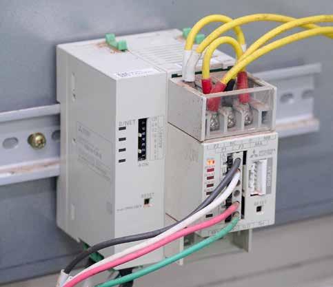
industrial ethernet book 03.2023
SOURCE: MITSUBISHI 58
Visit Website
SOURCE: MITSUBISHI
The operation of each machine is controlled based on data from the energy demand monitoring system.
Applications
EcoMonitorPlus" installed for demand monitoring.
High-channel density digital IO modules for factory automation
From a heat, reliability, and size considerations, an integrated device option must be carefully considered. When choosing integrated DI or DO devices, the robust operating specifications, diagnostics and the support of multiple input-output configurations are some of the important data points to keep in mind.
Digital Input
Digital Output
Size Support for different types of output driver configuration
Heat Size
Support for all input types
- Type 1, 2, 3 input
- Support for 24V and 48V input
Robust operating specifications
- Integrated demagnetization of inductive load
Heat -- when driving multiple outputs
Drive accuracy
Wire break detection Diagnostics
Considerations for digital input and output modules.
THERE IS A LOT OF INK SPILLED ON INDUSTRY
4.0 and the rising ubiquity of intelligent sensors on the factory floor. While sensor proliferation is something we clearly see in factories, process plants, and even in newer building automation systems, one important change this ubiquity of sensors necessitates is the requirement to process a large number of IOs within typically the same old controller form-factor. The IOs can be digital or analog. This requires architecting a high-density IO module with size and heat constraints. I will focus on the digital IOs in this article and take on the analog IOs in a subsequent piece.
Typically, the digital IOs in PLCs were conditioned using discretes like resistors/ capacitors or driven using individual FETs. The need to minimize the footprint of the controllers along with the real requirement of being able to process 2x to 4x the number of channels are pushing a move away from discrete implementation to an integrated approach.
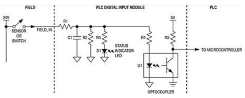
We could spend this entire article talking about the disadvantages of a discrete approach, especially when the number of channels being processed per module is eight or higher – but suffice it to say that high heat/power dissipation, the unwieldy number of discrete parts required (both from a size and a (Mean Time Between Failure) MTBF
perspective) and the need to have a rugged system specification have almost completely rendered the discrete approach unworkable.
The table above shows the technical challenges of architecting a high-density digital input (DI) and digital output (DO) modules. Size and heat are considerations in both Di and DO systems.
For digital inputs, it is also important that different types of inputs are supported – both types (type 1,2,3) of inputs and, in some cases, 24V and 48V inputs. In all cases, robust operating specifications are very important and sometimes wire break detection is crucial.
For digital outputs, systems use different FET configurations to drive the load. The accuracy of the drive current is generally an
important consideration. And in many cases, diagnostics are important.
We will discuss how an integrated solution can help with some of these challenges.
Designing a High-Channel Density Digital Input Module
A traditional discrete design uses a resistor divider network to convert a 24V/48V signal to something a microcontroller can use. There can be a discrete RC filter at the front as well. If isolation is a requirement, an external optocoupler is sometimes used. The figure below illustrates a typical discrete approach to implement a digital input circuit.
This type of design is good for up to a certain number of digital inputs; say 4 to 8 per
59 03.2023 industrial ethernet book Technology
ANALOG DEVICES
SOURCE:
A traditional digital input design using discrete logic.
board. Any number beyond that and it rapidly becomes impractical. The different issues with such a discrete implementation include:
• High power consumption and associated board hot spots.
• One optocoupler needed for each individual channel.
• Too many components resulting in low FIT rate and even requiring a larger formfactor.
Most importantly, a discrete design approach means the input current increases linearly with input voltage. Assume a 2.2KΩ input resistor and 24V VIN. When the input is 1, i.e., at 24V, the input current is 11mA, which equates to power consumption of 264mW. For an 8-channel module, the power consumption is over 2W and for a 32-channel module, the power consumption is over 8W.
Purely from a heat perspective, this discrete design cannot support multiple channels on a single board.
One of the biggest advantages of an integrated digital input design is significantly lower power consumption and thus heat dissipation. Most integrated digital input devices allow for configurable input-current limiting, dramatically reducing power consumption.
With current limit set to 2.6mA, the power dissipation is reduced significantly to approximately 60mW per channel. An 8-channel digital input module can now be rated at under half a watt as shown.
Another reason going against a discrete logic implementation is that sometimes DI modules must support different types
of inputs. The standard 24V digital input specification published by the IEC is divided into types 1, 2, and 3. Types 1 and 3 are generally lumped together as the current and the threshold limits are very similar. Type 2 has a 6mA current limit, which is much higher. With a discrete approach, this would require a redesign since most discrete values would need to be updated.
However, integrated digital input products can typically support all these three types. Natively, types 1 and 3 are always supported by integrated digital input devices. However, to meet the minimum 6mA current requirement for type 2 inputs, we need to use two channels in parallel for one field input. And just adjust the current limit resistors. There would be a board change, but it is minimal.
For example, the current Maxim Integrated DI devices have a current limit of 3.5mA/ channel. So, as shown, we would use two channels in parallel and adjust the REFDI resistor and the RIN resistors if the system must interface with type 2 inputs. For some of the newer parts, we can also select the current value using a pin or through software.
To support a 48V digital input signal (not a very common requirement) would require a similar process where one would have to add an external resistor to adjust the field side voltage threshold. The value of this external resistor is set so that Current limit * R + threshold at pin meets the field side voltage threshold specification (defined in the data sheet of the device).
Finally, since digital input modules are interfacing with sensors, they must be
designed to robust operating specifications. When implemented using discretes, these protections must be carefully designed. When choosing integrated digital input devices, ensure these come with these industrial-ready specifications:
• Wide Input voltage range (up to 40V for example).
• Ability to operate from field supply (7V to 65V).
• High ESD (±15kV ESD Air Gap) and surge tolerant (typically 1KV).
It is also very useful to have over voltage and over temperature diagnostics so that the MCU can take appropriate action.
Designing a High-Channel Density Digital Output Module
A typical discrete digital output design features a FET with drives circuitry driven by the microcontroller. There are different ways of configuring the FET to drive the microcontroller.
The definition of a high-side load switch is that it is controlled by an external enable signal and connects or disconnects a power source to a given load. Compared to a low-side load switch, a high-side switch sources current to the load, while the low-side type connects or disconnects the load to ground, and therefore sinks current from the load. While they both use a single FET, the problem with the low-side switch is that the load could get shorted to the ground. High-side switches protect the load from shorts to ground. But the low-side switch implementation is marginally lower cost. Sometimes output drivers are also configured as push-pull that requires two MOSFETs. See the following Figure 6:
Integrated DO devices can incorporate multiple DO channels in a single device. Since the FET configuration is different for high-side, low-side, and push-pull, different devices are available to implement each type of an output driver.
Built-In Demagnetization for Inductive Loads
One of the key advantages of an integrated digital output device is that demagnetization for inductive loads is built-in to these devices. An inductive load is any device that has coils of wire, which when energized, generally
60 industrial ethernet book 03.2023 Technology # of DI Channels Estimated Power Consumpton 8 2.1 W 16 4.2 W 32 8.4 W 64 16.9 W # of DI Channels Estimated Power Consumpton (discrete approach) Estimated Power Consumpton (discrete approach) 8 2.1 W 0.48 W 16 4.2 W 0.96 W 32 8.4 W 1.92 W 64 16.9 W 3.84 W
perform some mechanical work, for example solenoids, motors, and actuators. The magnetic field caused by the current flow can move the switching contacts in a relay or contactor, operate solenoid valves, or rotate a shaft in a motor. Mostly, engineers use a high-side switch to control the inductive load, and the challenge is how to discharge the energy in the inductor when the switch opens, and the current is no longer sourced to the
load. The negative impacts of not discharging this energy correctly include potential arcing of relay contacts, large negative voltage spikes damaging sensitive ICs, and the generation of high frequency noise or EMI that can affect system performance.
In a discrete implementation, the most common solution to discharge the inductive load uses a free-wheeling diode. In this circuit, while the switch is closed, the diode
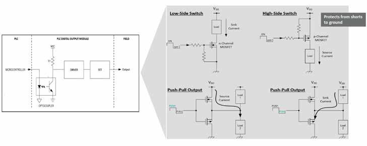

is reverse-biased and does not conduct any current. When the switch opens, the negative voltage across the inductor forward biases the diode, allowing the stored energy to decay by conducting the current through the diode until steady state is reached and the current is zero.
For many applications, especially those found in industrial applications that have many output channels per IO card, this diode is often physically quite large and adds
61 03.2023 industrial ethernet book Technology
Using 2-channels in parallel to support a type 2 digital input.
SOURCE: ANALOG DEVICES
Different configurations used for digital output drivers.
SOURCE: ANALOG DEVICES
significant extra cost and size to the design.
Modern digital output devices implement this function within the device using a kind of active clamping circuitry. For example, Maxim Integrated implements a patented safe demagnetization (SafeDemagTM) feature that allows our digital-output devices to safely turn off loads with unlimited inductance.
More details are available in an application note on Maxim Integrated’s website: https:// www.maximintegrated.com/en/design/ technical-documents/app-notes/6/6307.html
There are many important factors when selecting a digital output device. Some of the following data sheet specifications should be considered carefully:
• Look at the maximum continuous current rating and ensure that if needed, you can parallel multiple outputs to get a higher current drive.
• Ensure the output device can drive multiple channels with high currents (over the temperature range). Refer the data sheet specifications to ensure the on-resistance, supply current, and thermal resistance values are as low as possible.
• The output current drive accuracy specification is also important.
Diagnostic information is also essential to recover from some out-of-range operating conditions. First, you want diagnostic information reported per output channel. This will be temperature, overcurrent, open, and shorts. On a global (chip) basis, some important diagnostics are thermal shutdown, VDD undervoltage, and SPI diagnostics. Look for some or all of this in the integrated digital output device.
Programmable Digital Input/ Output Device
Once we start integrating DI and DO on an IC, it allows us to build products that are configurable. Here is an example of a 4-channel product that can be configured as an input or an output.
This has a DIO core, which means a single channel can be configured as a DI (type 1/3 or type 2) or a digital output in either a high-side or in a push-pull mode. The current limit on the DO can be set from 130mA to 1.2A. Demagnetization is built-in. To switch between type 1/3 or type 2 digital inputs, we
only need to set a pin and no external resistors are needed.
These devices are not only very configurable but also ruggedized to work in an industrial setting. This means high ESD, supply voltage protected up to 60V and line to ground surge protection. This is an example of something completely different (a configurable DI/DO module) possible with an integrated approach.
Conclusion
Once you are designing a high-density digital input or output module, it becomes clear that beyond a certain channel density a discrete implementation does not make a lot of sense. From a heat, reliability, and size considerations, an integrated device option must be carefully considered.
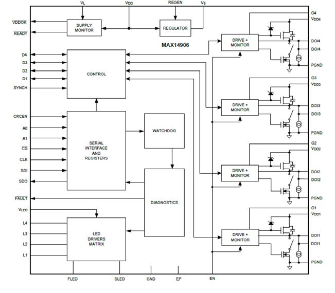
When choosing integrated DI or DO devices, the robust operating specifications, diagnostics, and the support of multiple input-output configurations are some of the important data points to keep in mind.
Technology article by Analog Devices.
Visit Website
62 industrial ethernet book 03.2023 Technology
SOURCE: ANALOG DEVICES
A configurable DI/DO product for a 4-channel implementation.
Artificial intelligence computing system
Advantech launches MIC-733 AI computing system based on NVIDIA Jetson AGX Orin.

THE NVIDIA JETSON AGX ORIN-BASED AI computing system is designed for the growing trend of video + AI + 5G applications, MIC-733 features superior computing power, flexible video input support, and wireless communication. Buttressed by 24/7 remote management support, MIC-733 is the best industrial edge AI computing system for AMR/AGV applications, and it is ready for the coming opportunities in smart agriculture and smart transportation.
MIC-733 is a compact fanless system capable of enduring wide operating temperatures (-10 ~ 60 °C; 14 ~ 140 °F) found in outdoor/harsh environments. It delivers a flexible array of expansion slots and multiple I/O — including 4 x USB 3.2, 2 x Mini-PCIe, and 2 x M.2.
Additionally, it offers iDoor and iModule expansion and support for diverse peripherals. There is also I/O module customization available through the Mini-PCIe and full PCIe interfaces. This includes the use/modification of CANBus controllers, Cameralink frame grabbers, or PoE modules for IP cameras.
High-performance AI applications
The Advantech MIC-733 computing system leverages the powerful NVIDIA Jetson AGX Orin system-on-module (SOM) for energy-efficient autonomous machines. These solutions accelerate NVIDIA AI software stacks with up
to 4x the CUDA cores and 8x the performance of the NVIDIA Jetson AGX Xavier modules. In addition, these solutions support multiple sensors and the latest high-speed interfaces.
Support for Multiple Video Inputs
Video AI has become mainstream for edge AI analytics. However, existing video equipment uses various formats and has greatly challenged edge AI integration. In order to integrate existing video with AI computing, MIC-733 provides support for multiple video inputs, including GMSL, USB, and PoE.
By inserting a GMSL card, MIC-733 can support 2 x GMSL2 cameras. MIC-733 is equipped with 4 x USB 3.2 Gen2 (10Gbit/s) for high data transmission USB cameras. With iModule expansion, the MIC-733 version can support 8 x USB 3.2 Gen2, 4 x GbE PoE or 8 x GMSL2 cameras. To help implement AI video solutions at the edge, MIC-733 supplies up to 60W of power to cameras from 4 x PoE ports (which can be upgraded from 4 x LANs) to help customers integrate cameras. Customers can choose either 4 x 15W/port or 2 x 30W/port.
Wireless: 5G, 4G, and Wi-Fi
Furthermore, as large-scale deployment in diverse scenarios becomes increasingly common, developers require wireless solutions with greater flexibility. Accordingly, MIC-733
preserves Mini-PCIe expansion to support 4G/ Wi-Fi modules for mobile communication. Also, with the growing demand for 5G communication, MIC-733 has a dedicated M.2 3052 for 5G applications.
MIC-733 is aimed at helping developers with high-performance AI applications at the edge, large-scale deployment, and data security during implementation. Advantech collaborates with Allxon to provide a 24/7 remote management service on the NVIDIA Jetson edge AI and robotics platform, enabling large-scale deployment and device management through over-the-air (OTA) and out-of-band (OOB) service.
MIC-733 is also Azure IoT-certified with the Microsoft reference configuration. In addition, the Azure Edge Managed Program, Microsoft Defender for IoT, delivers threat detection to the device’s operating system and applications.
To conclude, MIC-733 with NVIDIA Jetson AGX Orin delivers superior computing power, flexible video inputs and wireless communication, yielding a solution capable of empowering video + AI + 5G computing at the edge.
63 03.2023 industrial ethernet book Product News
Learn More
Advantech
New offerings facilitate powered, last-mile connectivity for factory and building automation through real-time power management, telemetry and extremely low standby power.
SOURCE: ADVANTECH
Single Pair Ethernet for IIoT applications
SPE 10BASE-T1S and 100BASE-T1 devices transform IIoT at the edge and in higher-speed applications.
Microchip’s SPE offering reduces cost and complexity of IIoT edge devices while supporting higher-speed Ethernet-everywhere architectures and applications.
SPE technology solution
SPE technology is setting the stage for all-Ethernet IIoT and industrial Operational Technology (OT) networks that are built with a new class of synchronized low-speed Ethernet edge devices and a simplified cabling infrastructure for latency-sensitive traffic streams.
Microchip Technology has announced new industrial-grade SPE products that will help fulfill SPE’s promise, from 10BASE-T1S MAC-PHYs that more easily connect edge IIoT devices to the cloud, to industrial versions of its 100BASE-T1 Time Sensitive Networking (TSN) Ethernet PHY transceivers and switches that enable higher-speed applications across far-reaching Ethernet networks.
“Microchip is helping to fuel the adoption of zonal architectures in industrial applications with our new MAC-PHYs that connect to many of Microchip’s microcontrollers (MCUs) to reduce the design complexity and implementation costs for bringing a host of sensors, actuators and other products into the new 10BASE-T1S network infrastructure,” said Matthias Kaestner, vice president at Microchip.
“With these new 10BASE-T1S MAC-PHYs and
industrial versions of our 100BASE-T1 TSN products, we are making it easier to connect the physical world to the cloud while enabling a seamless Ethernet architecture throughout the IIoT and other industrial networks.”
Simplified architecture
Microchip’s new LAN8650 and LAN8651 10BASE-T1S MAC-PHY Ethernet Controllers with Serial Peripheral Interface (SPI) simplify the implementation of zonal architectures by enabling basic MCUs, rather than higher-level MCUs with a Media Access Controller (MAC), to be used when creating sensors, actuators and other devices for the edge of OT and IT networks. These low-speed devices do not need their own communication system, and Microchip’s MAC-PHYs connect them into a standard Ethernet system all the way to the cloud over simple twisted-pair wiring.
For industrial applications that require higher bandwidth, designers can use MCUs with an integrated Ethernet MAC. Microchip now offers an industrial-grade version of its LAN8770 100BASE-T1 Ethernet PHY Transceiver that provides 100 Mbps transmit and receive capability over a single Unshielded Twisted Pair (UTP) cable.
Microchip’s SPE portfolio is enhanced with industrial-grade versions of its LAN937x and LAN938x Gigabit Ethernet TSN Switches with integrated 100BASE-T1 PHYs. These scalable, secure and compact SPE switches
include hardware time-stamping features for supporting IEEE 802.1AS (gPTP) and IEEE 1588v2 (PTP) time synchronization, among other TSN functionality. Energy-efficiency features include ultra-deep-sleep power down with remote wake for battery applications.
“Microchip’s industrial-grade 100BASE-T1 offerings reduce cost, wiring and installation complexity by enabling a complete SPE network from device to server,” said Charles Forni, vice president of Microchip’s USB and networking business unit. “Our industrialgrade SPE offerings are built to withstand harsh environmental conditions across an expanded temperature range while delivering enhanced performance, such as safety, security and extended cable reach, to support industrial applications.”
Development tools
To support the design efforts of these new products a set of network analysis tools and evaluation boards are available including the LAN8651 EVB and EVB-LAN9383.
Microchip’s MPLAB® Harmony v3 provides software support to configure, debug and program designs, while the MPLAB Network Creator provides a quick and intuitive graphical interface for switch configuration.
64 industrial ethernet book 03.2023 Product News
Learn More
Microchip
SOURCE: MICROCHIP
For industrial applications that require higher bandwidth, designers can use MCUs with an integrated Ethernet MAC.
dataFEED OPC Suite Extended
File Read function in version 5.25 supports the integration of production data from XML files.
The new "File Read" function of dataFEED OPC Suite Extended V5.25 enables access to process data available via XML files. The dataFEED OPC Suite Extended is an all-in-one solution for OPC communication and cloud connectivity, providing access to controllers and IoT devices of leading manufacturers. With the new File Read functionality, the suite ensures access to brownfield PLCs, devices and machines that deliver data via XML files.
Fast and easy data integration
File Read allows process values from XML files to be integrated quickly and securely into production control applications such as MES or OEE via the standard OPC Classic or OPC UA interfaces. The production data can also be integrated into IIoT cloud solutions via MQTT or REST. Furthermore, there is the option of data logging for documentation, analysis, or verification in a separate database.
The dataFEED OPC Suite enables access to the controllers of leading manufacturers such as Siemens SIMATIC S7, Rockwell ControlLogix, B&R, Mitsubishi as well as Modbus controllers (e.g., from Wago). It acts as a gateway between the two OPC standards so that existing OPC
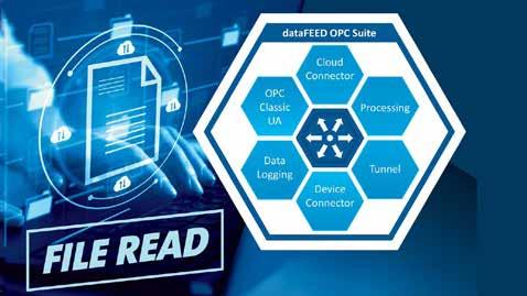
Classic components and applications can be integrated into modern OPC UA solutions for Industry 4.0 applications.
Production data is transferred to IoT Cloud or Big Data applications via the MQTT and REST protocols. The suite supports the storage of production data in a file, in an SQL database, or in MongoDB and CouchDB. Thanks to the extensive data pre-processing functionality,

CC-Link IE Field solutions
data can be easily and flexibly customized. With OPC UA Reverse Connect functionality, the suite also ensures secure communication between OPC UA components separated by firewalls or DMZs.
RT-Labs releases CC-Link IE Field Basic master and device stacks for industrial applications.
RT-Labs has announced the release of CC-Link IE Field Basic master and device software stacks as open-source and also under a dual license. CC-Link is an industrial network protocol which enables communication between a master (typically a programmable logic controller) and field devices (sensors and actuators). This protocol is particularly popular with industrial equipment manufacturers in Asia.
Both stacks are written in the C programming language and are available with extensive supporting documentation. They have been developed to run on microcontrollers (bare metal or RTOS) and Linux/Windows operating systems for maximum flexibility.
In addition, RT-Labs has made these stacks available as open-source for easy access for fast device evaluation and under dual-license (GPL version 3 and commercial). The stacks also include a porting layer, making adapting them for other operating systems straightforward.
These stacks include additional features (not typically included in other CC-Link stacks) which enable a master to search for nodes and remotely set a device’s IP address. These stacks represent an efficient way to integrate
the CC-Link IE Field Basic software stack in an industrial project.
For more information on RT-Labs’ portfolio of software stacks for a wide range of industrial communications protocols, visit: https://rt-labs.com/products/#industrialcommunication-stacks
The software is available as open-source and dual license with extensive documentation to help with integration details.
RT-Labs
Visit Website
65 Focus 03.2023 industrial ethernet book Product News
Website
Softing Visit
SOURCE: SOFTING
SOURCE: RT-LABS
iPoE budget control technology
U.S. Patent for iPoE budget control technology protecting industrial switches from damage.
THE UNITED STATES PATENT AND TRADEMARK Office (USPTO) has issued a new patent for Antaira's iPoE Budget Control, a software innovation that helps to avert damage to Antaira industrial PoE switches by preventing the switch from overrunning its already set PoE budget. Once a switch’s power budget crosses an overdrawn parameter, iPoE Budget Control will begin to shut off the power on the switch's PoE ports. Shutdown starts with the highest port number, progressing downward to port 1 with the highest priority.
iPoE Budget Control
Here is how iPoE Budget Control works. A low voltage PoE switch can be powered by 12-52VDC while still providing the 48-52VDC to powered devices required by the IEEE standard. This is made possible by a power booster built into the switch circuitry. However, since PoE switches operate more efficiently at 36VDC than at 12VDC, the power budget will change depending on the input voltage. At 12VDC the switch budget is 90W, but at 24VDC it is 150W, and at 48-55VDC it is 240W. Antaira iPoE Budget Control auto-senses the voltage input and limits the PoE power budget to 90W
when the switch is powered by only 12VDC. Conversely, iPoE Budget Control will increase the budget to 240W if the voltage rises to 48VDC. This protects the industrial switch from damage.
Five port switches
Antaira iPoE Budget Control is featured in the company's LNP-C501G-SFP-BT-24 and
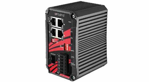
LNP-C501G-SFP-BT-24-T 5-port industrial Gigabit IEEE PoE++ unmanaged Ethernet switches. Antaira plans to integrate iPoE Budget Control into more of its industrial managed and unmanaged switches.
Antaira
Four times more performance
New backplane bus of the popular B&R I/O system increases performance of the X20 system.
B&R NOW OFFERS THE X2X+ BACKPLANE BUS AS an option, increasing the performance of the X20 system by a factor of four. And because all existing X20 I/O modules are already compatible with X2X+, all it takes to build more powerful machines are bus modules.

The advantages of this new bus are particularly apparent in applications that involve many I/O modules or high data volume but where short cycle times are imperative.
It is even possible to set up two separate cycle times so that less time-critical data is transported more slowly and generates less network and processor load. In this way, complex high-speed processes can be controlled reliably using cost-effective standard hardware.
High sampling rates
X2X+ enables faster data transfer and up to four times faster response times. In combination with this higher bandwidth, large amounts of data can be handled better and higher sampling rates can be achieved. This is an advantage when measuring vibration, for example, and results in more accurate condition monitoring across the board.
With its well thought-out details and a sophisticated ergonomic design, the X20 System is more than a remote I/O system. It is a complete control solution that, depending on the user's demands and individual application requirements, the X20 System family makes
it possible to combine the exact components necessary. B&R
66 Product News
More
Learn
SOURCE: ANTAIRA industrial ethernet book 03.2023
More
Automation Learn
SOURCE: B&R
Digital I/O remote module
Digital I/O remote module with integrated output
Delta announced the launch of its R2-EC0902D0 32 digital input/output remote module. Featuring 32 integrated relays on the output, supporting 2 A at 30 VDC/ 250 VAC per channel, and 32 24 VDC digital inputs, the unit greatly simplifies the implementation of digital I/O on EtherCAT networks. The high level of integration reduces system costs by eliminating the need for a separate coupler, digital input/ output modules, and external relays.
EtherCAT is predicted to grow above 7%, supporting the view that continued innovation around this technology is needed. While advanced automation capabilities are well covered, more straightforward capabilities, such as hardware integrating EtherCAT for digital I/O, are not as refined.
Instead, system integrators have relied on couplers, digital input and output modules, and external relays. The R2-EC0902D0 DI/DO mixed remote module removes this complexity and associated cost, integrating digital I/O into a single, EtherCAT-capable unit.
The R2-EC0902D0 features an input and output EtherCAT port, allowing for daisychaining. At the front of the 120 mm wide DIN-rail unit, power, communication, and alarm
relays for EtherCAT networks.
indicators are set into the housing for good visibility. Indicators for each of the 32 inputs and outputs are located in the center of the face plate. All the optical coupler inputs are grouped on one side, with the digital outputs placed on the other. The 32 digital outputs are implemented using normally-open dry contact relays. These operate at up to 1 Hz and have an off/on response time of 10 ms, and on/off response time of 5 ms. On the input side, PNP/
Scalable embedded box PC
NPN configurable sink/source signals of up to 1 kHz can be acquired with a response time of 300 μs. The R2-EC0902D0 is designed for industrial automation engineers looking for a digital I/O solution with a large number of channels that also supports EtherCAT.
Powerful and expandable embedded box PC for mission-critical IIoT applications at the edge.
IEI Integration Corp. has announced the powerful, reliable and scalable embedded box PC, TANK-XM811, with 13th Gen Intel Raptor-Lake Core processor. With Intel Hybrid Technology integrated for outstanding multithreaded performance, multiple expansion options via wide variety of expansion modules and rugged design for reliable operation in harsh environments, the TANK-XM811 is designed for advanced IIoT applications at the rugged edge.
Even edge computing requires higher speeds of data processing, increased data quantity, and heavier workloads, the TANK enables the acquisition, processing, and display of incoming data in near real-time.
Powerful processing
The TANK-XM811 powered by 13th generation Intel Core Raptor-Lake processor offers nextgeneration performance to deal with expanding workloads where data is created and taken action.
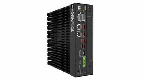
Thanks to Intel Hybrid Technology that combines performance cores (P-cores) and efficient cores (E-cores), the TANK-XM811
delivers higher workflow efficiency and lower power consumption.
Multiple expansion options
Besides the built-in I/O, a variety of expansion modules and chassis options are available to extend the core I/O, providing customizable expansion options that support
more add-on cards, GPU and AI accelerator cards for system integrators and developers to create comprehensive industrial applications, such as edge computing and AI vision inference.
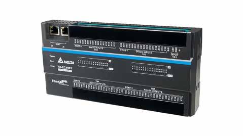
67
Delta Electronics Visit Website
SOURCE: DELTA
IEI Visit Website
SOURCE: IEI Product News 03.2023 industrial ethernet book
System-on-Module adds TSN capability
System-on-Module combines Open Standard Module with dual GbE LAN and TSN functionality.
New SoM from Kontron offers significantly more functionality and combines the powerful Quad Arm processor in the smallest of spaces plus the advantages of the Open Standard Module specification (OSM).
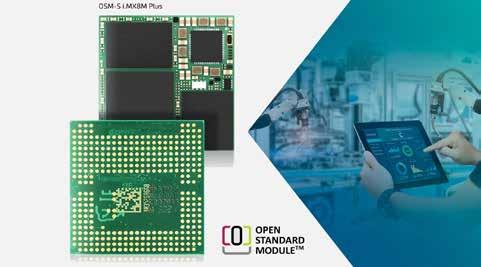
Kontron is expanding its existing 30 x 30 mm OSM portfolio with the system on-Module OSM-S i.MX8M Plus with 1.6 GHz quad core and an AI processor, 64 GB eMMC and 4 GB LPDDR4 RAM. This SoM is the first to come in the OSM form factor Size S offers the i.MX8M Plus processor with two GbE and two CAN interfaces. The directly solderable module without plug connections can be equipped, tested and programmed by machine at low cost.
The SoM is high-performing, compact, costeffective and the first module in the form factor S to offer this wide range of functions. It combines all the advantages of the i.MX8M Plus processor and the OSM standard in the smallest of spaces.
In addition, it offers the highest performance for computing-intensive applications and 3D graphics applications as well as a large number of communication interfaces. Numerous digital I/Os and serial
communication interface as well as PWM and two SDIO interfaces predestine the module for Industry 4.0 applications.
A major advantage of the TSN communications technology lies in the far-reaching independence from the physical transmission layer. Wired and wireless connections, such as the latest 5G mobile
radio standard, are made possible. The first customer samples of the System-on-Module OSM-S i.MX8M Plus will be available at the end of Q2/2023.
Cloud-based IIoT development tool
Quick-Connect Studio offers cloud-based system development tool to dynamically create IIoT software.
Quick-Connect Studio from Renesas accelerates the design cycle by enabling customers to build rapid prototypes and develop production-level software before designing hardware. This new online, cloud-based IoT system design platform enables users to graphically build hardware and software to quickly validate prototypes and accelerate product development.
Today’s development cycle is cumbersome. Engineers research and define the project, collect device information and requirements, layout hardware, develop software, test, and iterate until the product is ready to release to market. This process is typically done sequentially, and each step takes a significant amount of time. Often software development phase consumes engineering power and ultimately becomes the biggest bottleneck.
With Quick-Connect Studio, engineers can now perform hardware and software development simultaneously. This is a radical shift in the industry, enabling designers to build software immediately with the ability to quickly reconfigure and test product ideas. This yields dramatic time savings and reduces risk as engineers can validate designs before committing to hardware layout.
Quick-Connect Studio empowers engineers to graphically drag and drop device and subsystem blocks on the Cloud to build their solution. After placing each block, users can generate, compile, and build software automatically, a major shift towards the no-code paradigm of development. This makes building production-level software as easy as
piecing building blocks together. With QuickConnect Studio, users can rapidly build a full solution in the cloud and deploy to hardware in under 10 minutes.
Renesas
68 Product News
More
Kontron Learn
SOURCE: KONTRON industrial ethernet book 03.2023
Learn More
SOURCE: RENESAS
Industrial Ethernet Book
The only publication worldwide dedicated to Industrial Networking and the IIoT. Visit iebmedia.com for latest updates.

View and/or download latest issue of Industrial Ethernet Book and past issues. Search our database for in-depth technical articles on industrial networking.


Learn what's trending from 5G and TSN, to Single Pair Ethernet and more. Keep up-to-date with new product introductions and industry news.

New website offers deepest, richest archive of Industrial Ethernet and IIoT content on the web.
