Synchronous AC Servo Control Systems Division
BS Servo X Series
Headquarters 2068-3, Ooka, Numazu-shi, Shizuoka-ken, 410-8510, JAPAN TEL: 81-(0)55-926-5141 FAX: 81-(0)55-925-6501 Homepage Address
http://www.toshiba-machine.co.jp
BS Servo Amplifiers Cautions on safety ● Before using, read through and completely understand the appropriate instruction manual provided separately. ● The contents carried in this catalog may be subject to change without prior notice to effect improvements.
Export of the products listed on this catalog
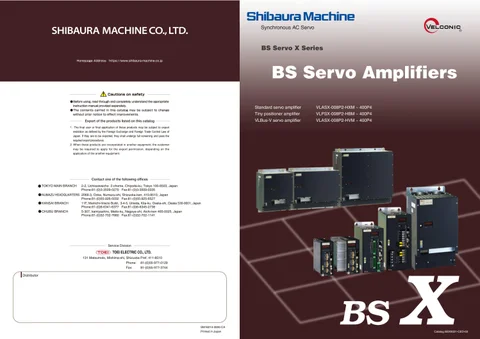
Standard servo amplifier
VLASX-008P2-HXM ~ 400P4
Tiny positioner amplifier VLBus-V servo amplifier
VLPSX-008P2-HBM ~ 400P4 VLASX-008P2-HVM ~ 400P4
1. The final user or final application of these products may be subject to export restriction as defined by the Foreign Exchange and Foreign Trade Control Law of Japan. If they are to be exported, they shall undergo full screening and pass the required export procedures. 2. When these products are incorporated in another equipment, the customer may be required to apply for the export permission, depending on the application of the another equipment.
Contact one of the following offices ● TOKYO MAIN BRANCH
2-2, Uchisaiwaicho 2-chome, Chiyoda-ku, Tokyo 100-8503, Japan Phone:81-(0)3-3509-0270 Fax:81-(0)3-3509-0335
● NUMAZU HEADQUARTERS 2068-3, Ooka, Numazu-shi, Shizuoka-ken, 410-8510, Japan Phone:81-(0)55-926-5032 Fax:81-(0)55-925-6527 ● KANSAI BRANCH 11F, Mainichi-Intecio Build., 3-4-5, Umeda, Kita-ku, Osaka-shi, Osaka 530-0001, Japan Phone:81-(0)6-6341-6377 Fax:81-(0)6-6345-2738 ● CHUBU BRANCH 5-307, kamiyashiro, Meito-ku, Nagoya-shi, Aichi-ken 465-0025, Japan Phone:81-(0)52-702-7660 Fax:81-(0)52-702-1141
Service Division
131 Matsumoto, Mishima-shi, Shizuoka Pref. 411-8510 Phone: Fax:
81-(0)55-977-0129 81-(0)55-977-3744
Distributor
SM16014-3000-CA Printed in Japan
BS
X
Catalog BSX0021-CED-03