Industrial Automation
IMI Norgren
Functional Safety Solutions for Safety Technology

Breakthrough engineering for a better world

IMI Norgren
Functional Safety Solutions for Safety Technology
Breakthrough engineering for a better world
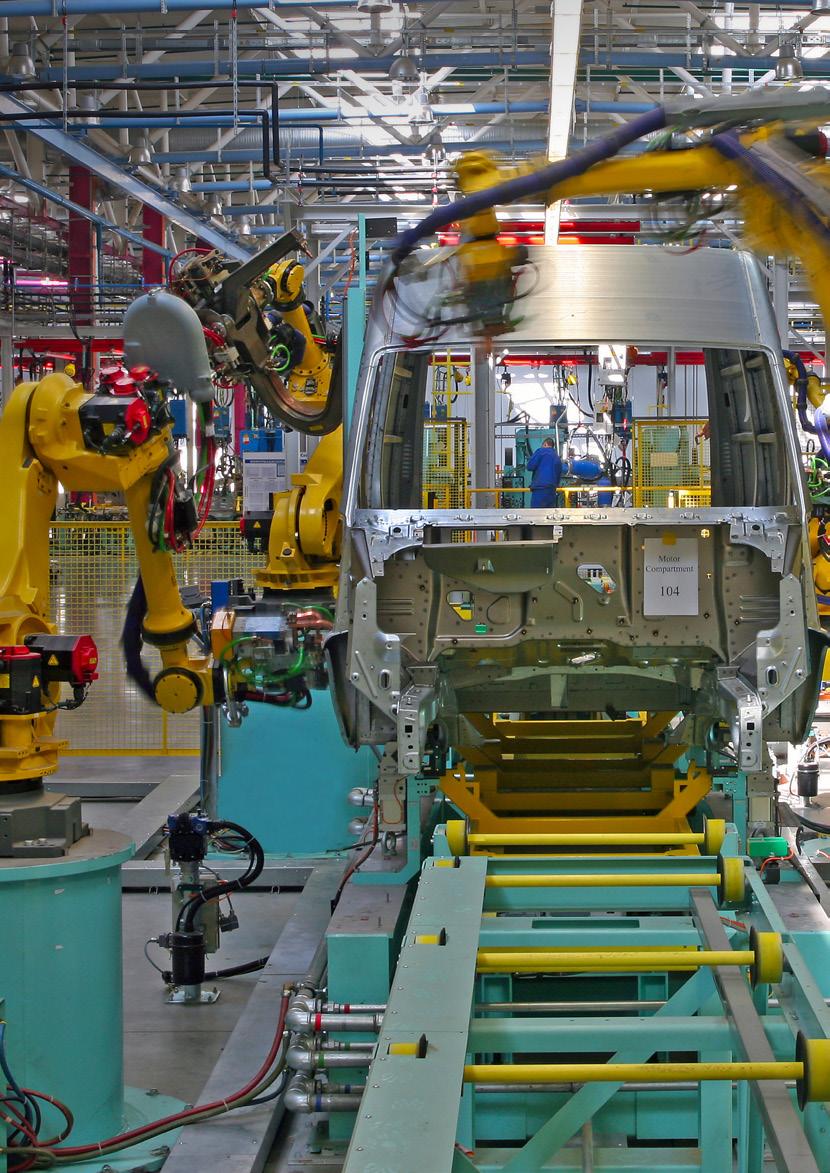
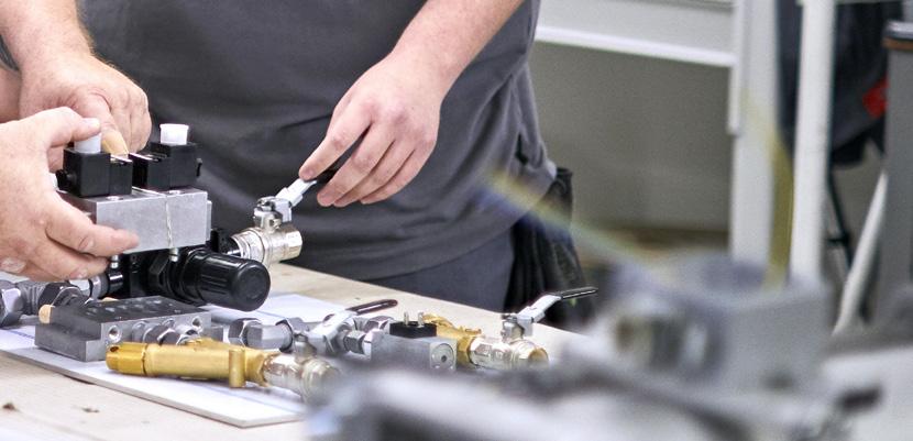
We create solutions for our customers which enable smarter, safer, more productive and sustainable factories, production lines and warehouse operations. Our pneumatic and electric motion systems help machine builders and end users around the world automate and optimise manufacturing and warehousing processes.
We have partnered with customers in industrial automation for over a century, applying our experience and innovation to create lasting value for their businesses. Our solutions support critical industries such as automotive, food and beverage, pharmaceuticals and even the space industry. We support the automation of precision manufacturing, product assembly, testing and packaging.
We use the latest digital technologies in our automation products and constantly innovate in close partnership with our customers. By applying our deep expertise, we can solve their toughest automation challenges, today and tomorrow. Through increased productivity, efficiency and safety, our customers can serve their own customers better, creating sustainable competitive advantage and delivering growth.
Our world-class product portfolio includes IMI Norgren, IMI Bimba, and IMI Bahr.

• Over 50 years experience in safety applications
• Safety applications EN ISO 13849
• Competent and professional consulting and system design of safety controls
• Very high B10 levels
• DGUV certified self-monitored safety valves
• Important safety features such as:
• Safe exhaust
• Safe position
• Safe stop
• Reliable reversing
• Safely limited speed and more
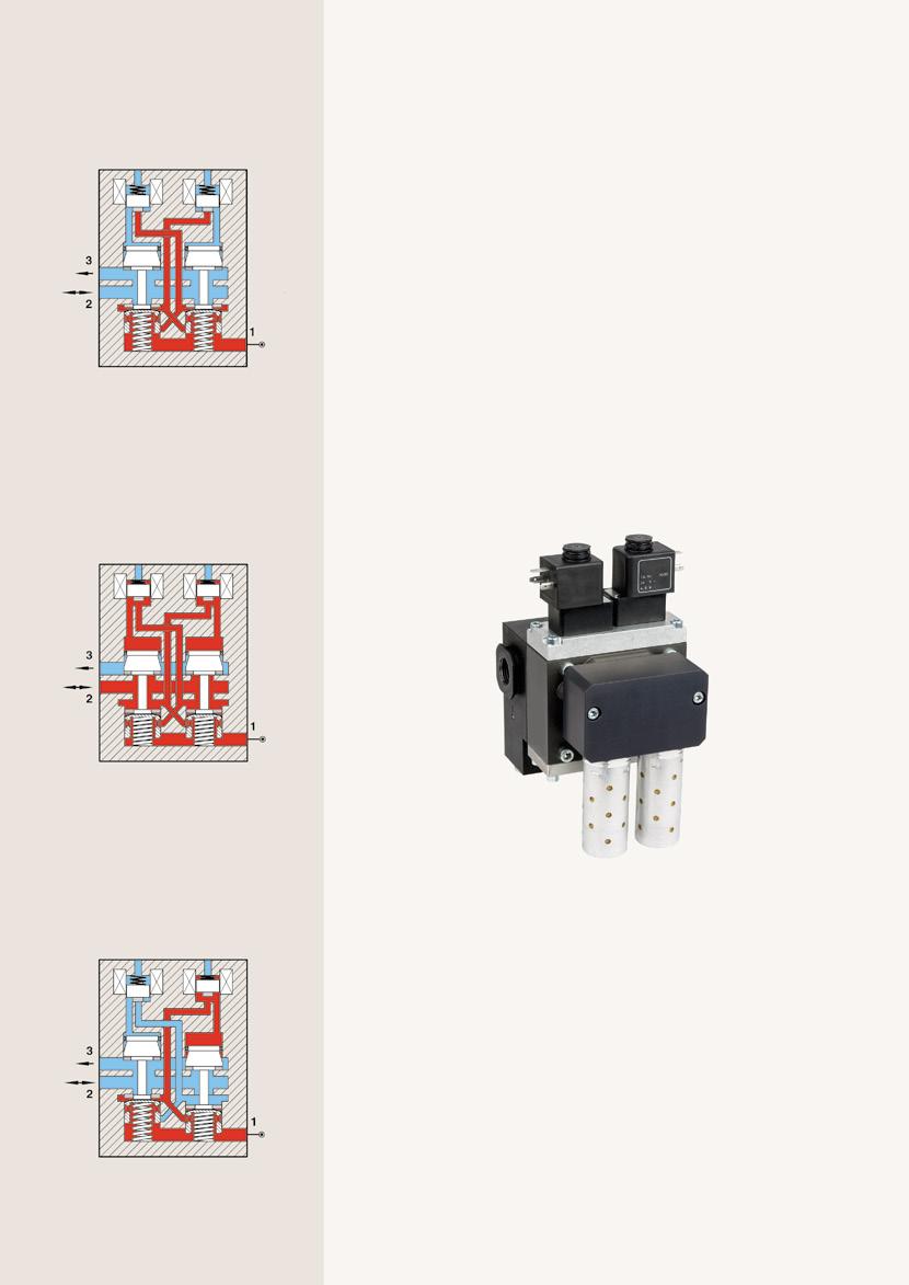
Functional diagram
Basic position
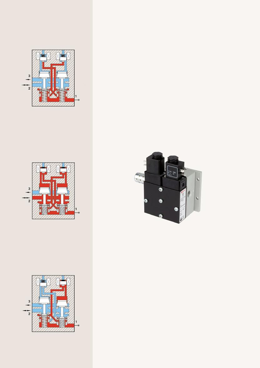
Channel "2" onto "3" Safety silencer relived
Working position
Both solenoids energised
• Sizes: DN 8, 20 and 32
• Port size: G1/4 ... G1
• Control: Pneumatic
The SCVA is a pneumatically monitored valve eliminating the need for further electronic systems. With the appropriate application, performance level "e" (cat. 4) of EN ISO 13849-1 is achieved for the safety function "Pressure building up from '1' to '2' and pressure dropping from '2' to '3'.
• Four port sizes in both BSP and NPT thread forms
• Requires only 50 micron filtration for cost effective operation
• Supplied complete with highly effective exhaust silencer
• Excellent B10 values represent extremely long service life until the necessary replacement (T10D -value) of the valves
High B10 levels
Channel "1" onto "2" turned on
Safety position
For unbalanced control, faulty solenoid, dirty valve, etc.
No additional electronic monitoring
Safe exhaust
Port 2 linked to 3
Example for safety functions for safe ventilation cat. 4 PL-e
In accordance with EN ISO13849
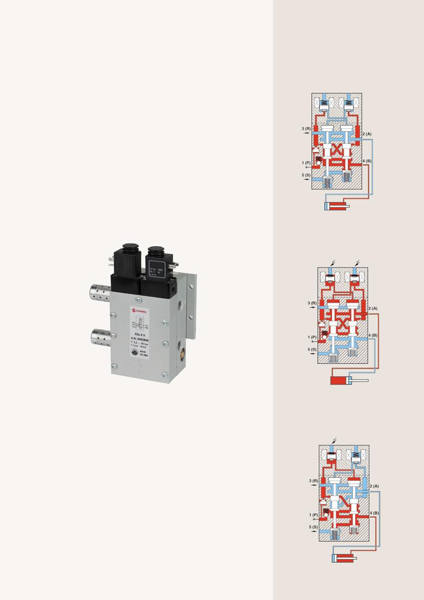
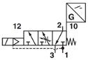
• Sizes: 10 mm
• Port size: G1/2
• Control: Pneumatic
The SCVA10 safety valve is pneumatically monitored and requires no cyclical monitoring or evaluation system. With the appropriate application, performance level "e" (cat. 4) of EN ISO 13849-1 is achieved for the safety function "Pressure building up from '1' to '2' and pressure dropping from '2' to '3' ".
• Redundant valve assembly, pneumatic self-monitoring
• Meets the standard EN ISO 13849, category 4, reaches Performance Level e and is DGUV certified
• Cost-efficient decentralized safety application
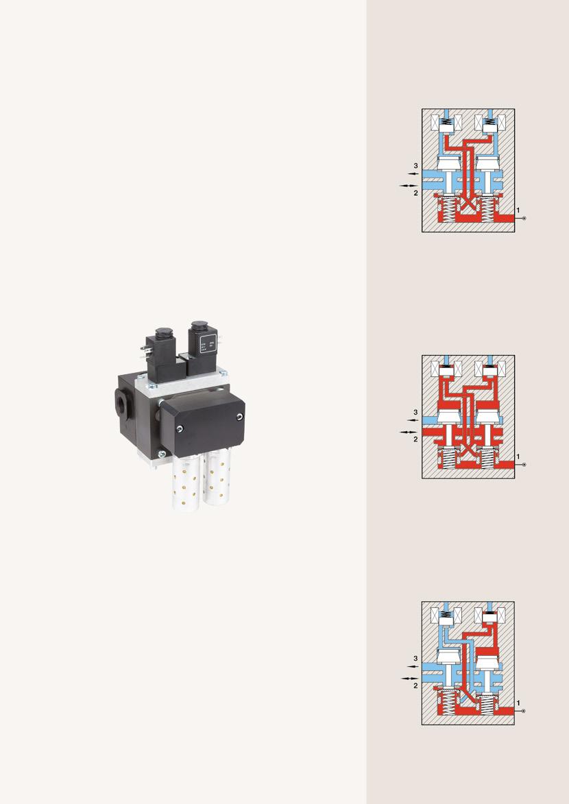
Example for safety functions for safe ventilation cat. 4 PL-e
Functional diagram
Basic position
Safety silencer relived
Working position
Both solenoids energised
Safety position
For unbalanced control, faulty solenoid, dirty valve, etc.
Functional diagram
Basic position
Channel "2" onto "3" Safety silencer relived
Working position
Both
Safety position
For unbalanced control, faulty solenoid,
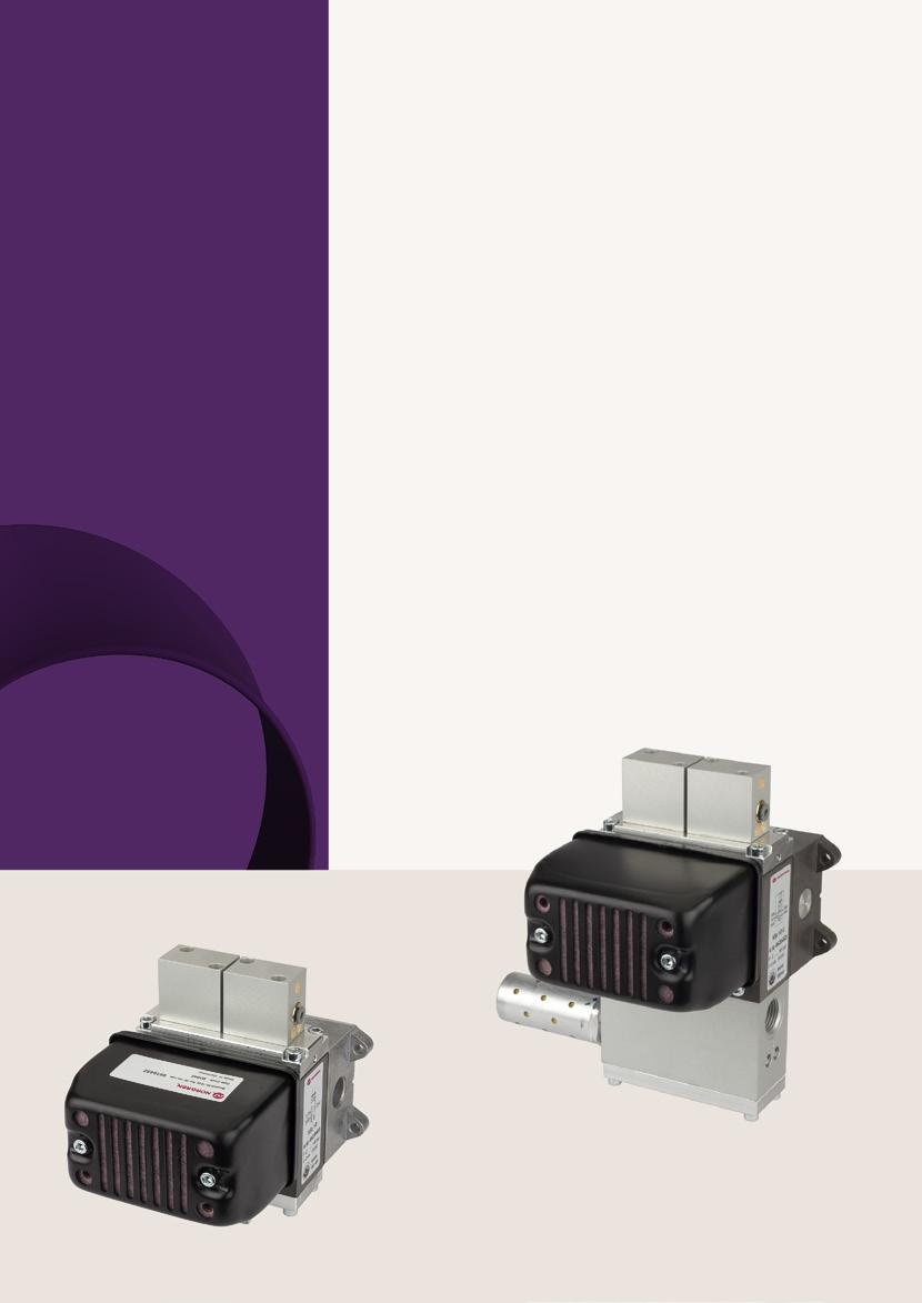
Cross monitored safety valve with integrated soft start and Excelon® connection
Series SCSQ10
• Sizes: 10 mm
• Port size: G1/2
• Control: Pneumatic
In applications requiring a controlled re-start of the air supply, the SCSQ10 includes a variable soft start function. This can be adjusted to suit the downstream volume and required fill rate. Like the SCVA, the SCSQ is pneumatically monitored to meet the requirements of current safety legislation and requires no additional electronics.
• Excellent B10 values represent extremely long service life until the necessary replacement (T10D -value) of the valves
• Can be mounted as part of a control system or connected to Excelon® air preparation units via integral adaptors
• Supplied complete with highly effective exhaust silencer
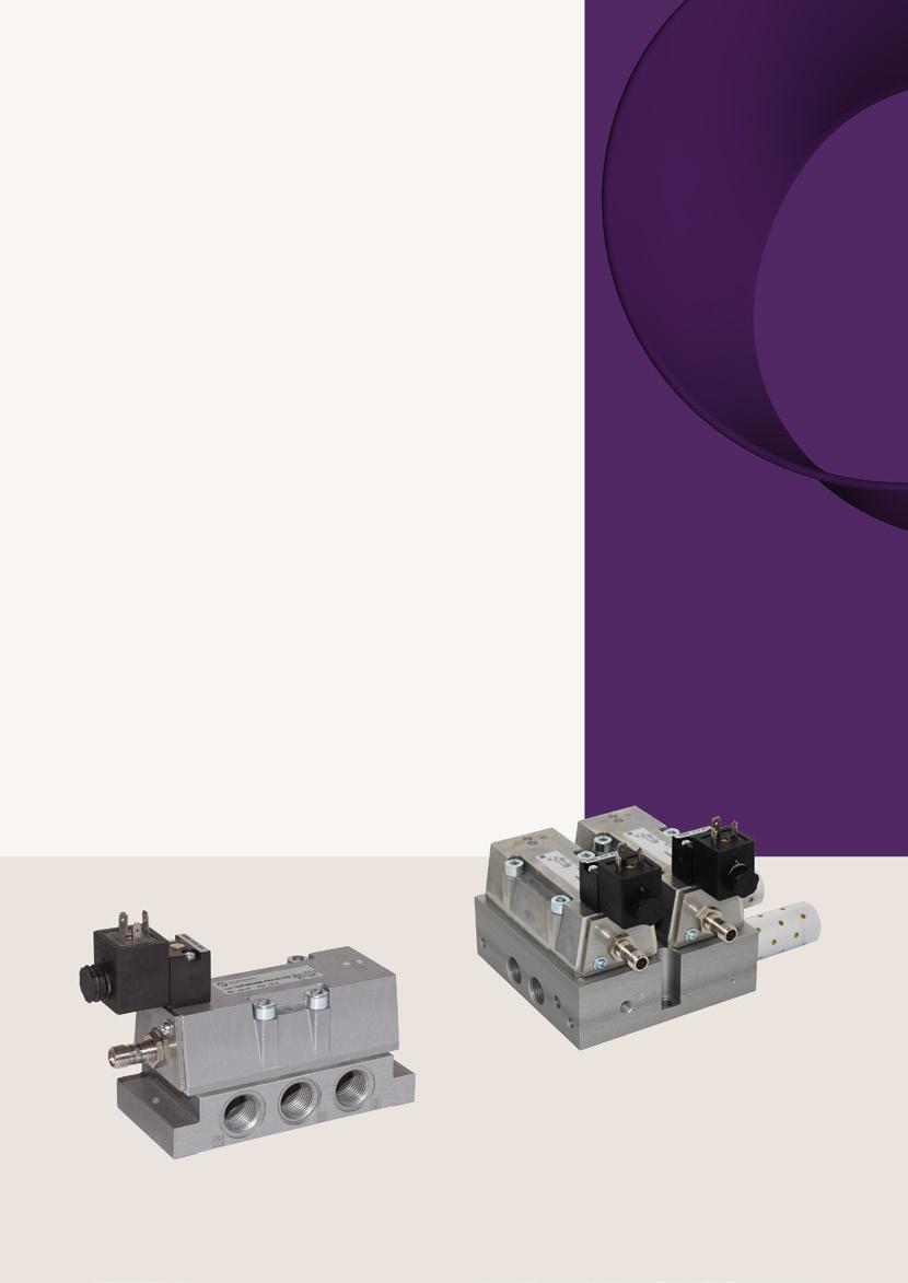
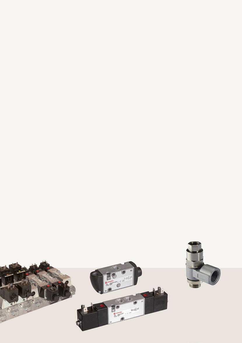
5/2 directional control valve
• Sizes: 8 mm and 10 mm
• Port size: G1/4 ... G1/2
• Control: Pneumatic
The 5/2-way safety valve consists of two mechanically separated pilot control systems and main valve systems. The valves are pneumatically operated and the dynamic self-monitoring system does not require additional electrical monitoring. With the approproate application, performance level "e" (cat. 4) of EN ISO 13849-1 is achieved. Excellent B10 values represent extremely long service life until the necessary replacement (T10D-value) of the valves
• Double valve control system, dynamic self-monitoring
• Fast exhaust capability
• Improves safety and reduces downtime
• No additional electrical monitoring required
DN 8, 10
Very high B10 value
Reliable reversing
Example of safety function safe reversing Cat 4 PL e
Safety silencers or Integrated bypass
Function of the dynamic selfmonitoring (diagnostic coverage 99%)
Not actuated basic position both magnets
Diagnostic coverage 99%
Channel 2 relieved 3
Channel 1 is switched on 4
Working position Driven both magnets
Channel 1 is switched on 2 Channel 4 relieved 5
Safety position With asymmetrical driving
Channel 2 relieved 3
Channel 1 is switched on 4
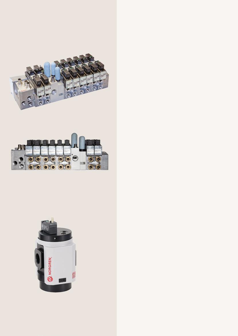
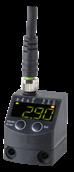
Pneumatic self-monitored 3/2- and 5/2-way
• Sizes: 5,0 ... 8,0 mm
• Port size: G1/2
• Control: Pneumatic
The pneumatic controlled 3/2 and 5/2-way safety valves have a redundant valve assembly. The intrinsically safe dual valve control system with dynamic self-monitoring functions guarantee the highest possible degree of diagnostic coverage at 99%, without the need for additional diagnostic components. Furthermore, this safe design does not require additional electronic diagnostics nor interval tests or cyclical circuits. These valves achieve the performance level „e“ (Category 4) in accordance with EN ISO 13849, DGUV certified. High B10 levels represent optimal durability until the necessary preventative replacement (T10D-value).
Control example two-hand control with pneumatic control 5/2-way safety valve XSz-4420
Two-hand control XSHC04
Dynamic selfmonitoring function
Performance level 'e' (Category 4)
5/2-way SXE ISO of electrical position monitoring
Series VSP55
• Sizes: base ISO3
5/2-way valves with additional electrical position monitoring for use in safety-related systems or subsystems. Using two valves in a redundant safety control it can realize a high performance level up to "e" (Category 4) in accordance with EN ISO13849.
Example control reliable reversing Cat. 4 PL-e
Single
Compact redundant control block for safety function safe reversing
3/2-way with position monitoring
Fieldbus and multipole connection
Modular in VS26 terminals used
• Sizes: 26 mm, ISO 15407-2
Integrated in the Valve Islands VS26 Series, these valves are suitable for application in safety-related systems. The 3/2way valves are electronically monitored and fail-safe without residual pressure suitable for safety function "safe ventilation". The soft start enables controlled increase of downstream pressure on startup. Through integration of the valve in the safety system in combination with downstream valve blanking disks, a two-channel function and high performance levels can be achieved (in accordance with EN ISO 13849). Only the righthand valve positions are pneumatically actuated and locked; the valve is closed on the left side. To order please use valve island configurator.
Function evaluation via enable signal
Optimum performance
Optimum performance
• 1/4...3/4 (ISO and NPT)
We offer a 3/2 Dump valve, with or without soft start, as a standard option in both Excelon® Plus 82 & 84 series. They perform the same function as an on/off manual valve but can be hard wired into a safety shut down circuit such as an emergency stop system (if using the solenoid version). A pneumatic pilot version is also available whereby the valve can be switched via an auxiliary pneumatic signal.
• Supporting designers in complying to ISO 12100, ISO 13849-1 and the European Machineries Directive 2006/42EC.
• Performance Level rated (PLc Cat. 1)
Safety function: Safe Venting
• B10 Value(s)
P82C and P82F: 1.4 million life test cycles
P84C and P84F: 1.1 million life test cycles
• Port size: G3/8 … G3/4
Whilst not including the cross monitoring function, these products have the facility to provide an electrical output indicating the valve status. This can be incorporated into the machine control system where required – for example in a 2 channel system requiring a level of redundancy. Available in both Excelon® and Olympian Plus ranges.
• Rate of pressure build up can be adjusted to suit the application
• High capacity dump facility for optimum performance
• Positively driven micro switch indicating valve position
Optimum performance
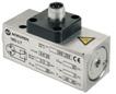
Two-hand control unit
Series XSHC04
• Tube size: O/D 4 mm
The standard IMI Herion two-hand start unit can be fitted to any machine function where the requirement exists for the operator to utilise both hands in order to begin operation. Both buttons need to be operated within 0.5 seconds in order to achieve an output. The unit is supplied as a strong, sealed unit designed to prevent accidental operation.
• Meets requirements of EN574 class IIIB
• No additional setting or adjustment required
Control example two-hand control with pneumatic control 5/2-way safety valve XSz-V
Two-hand control XSHC04
Designed to prevent accidental operation

5/2- and 5/3-way valves air pilot and solenoid pilot actuated
Series ISO˙STAR
• ISO 1 to ISO 3
• Port size: G1/4 ... G1/2c
Excellent B10 values due to special valve design.
3/2-, 5/2- and 2x 3/2 way
Series V60 ... 63
• Port size: G1/8 ... G1/2
High B10 values.
Pilot operated check valve (blocking valve)
Series 102GA
• Port size: G1/4 … G1/2 and 4 … 12 mm
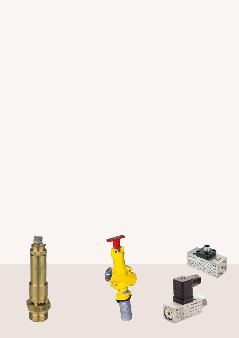
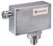
Safety pressure relief valves
Series 4440000
• Port size: G1/4 ... G3/4
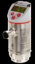
3/2-way Inline lockout valve Pressure switch
Series CR04
• Port size: G1/2 ... G1
When carrying out maintenance on machine installations, the safety of personnel is of vital importance. “LOTO” or “lock out tag out” is a primary function required before any work begins. The air supply to the area should be isolated and the downstream air exhausted quickly and safely then locked to ensure safety of the workforce. Our lock out valves provide a solution to this task, and are easily fitted into the system.
• Valves can only be locked in the “off” position and made secure with a padlock.
• Operating handle provides a clear, simple method of operation
• Complete with integral heavy duty silencer / muffler

Series 18D
• Port size: G1/4
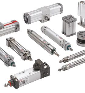
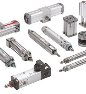
We offer a full suite of pneumatic and electropneumatic products for the efficiency and safety of many pneumatic applications.
Machinery Directive 2006/42/EC and EN ISO 13849
With an effective date 29.12.2009 the Machinery Directive 2006/42/EC replaced the previous Machinery Directive 98/37/EC and defines fundamental standards of Machine Safety in the European domestic market. Only machines, that comply with the demands of the Machinery Directive, are allowed to be introduced on the European market. This includes new machines as well as existing machines that have experienced significant or considerable variations or modifications or have served a different use. In accordance with conditions of the Machinery Directive and the guideline, compliant machines must be furnished with CE-labelling, Declaration of Conformity and the required user information. The harmonized standard EN ISO 13849 (Type B-norm) assists the Machinery Directive with the technical implementation of the safety demands and reliable control systems. It provides generally important principles in terms of the planning and evaluation of safety-related parts of a control system, control system architecture as well as the quality of risk reduction and the validation procedures for the safety function, categories and Performance Levels of safety-related parts of controls.

A machine should be constructed to guarantee safety as much as possible. Any potential danger must have its risk reduced/minimized by protections or measures e.g. a pneumatic safety control system. For unavoidable residual risk, the corresponding necessary documentation must be provided. A comprehensive and standardized risk assessment will take place at the beginning of the process for the evaluation of the machinery safety.
If in the risk analyses hazardous movements were detected then, in accordance with the danger, counteracting safety functions must be defined and provided. Only after more precise definition of the actual safety function can the corresponding subsystems of the safety control system be adequately executed and interpreted.
• Safe exhausting of a system
• Stop of a hazardous movement
• Stop and obstructing of a hazardous movement
• Reversing a hazardous movement
• Protection against accidental start-up and many others
From risk analysis (EN ISO 12100)
to Risk analysis (EN ISO 12100) for every SF
Identify the safety functions (SF)
Setting the properties of each SF
Determination of the required PL (PLr)
Realizing the SF, identifying the SRP / CS
Determining the PL of the SRP / CS from Category, MTTFD, DC avg , CCF
Software and systematic errors
Verification: PL ≥ PLr?
Validation: Requirements met? All SF analyzed? yes no no yes
Iterative process for the design of the safety-related components of the control system
SF = Safety Function
PL = Performance Level
SRP/CS = Safety Related Parts of Control Systems
MTTFD = Mean Time to Dangerous Failure
DCavg = Average Diagnostic Coverage
CCF = Common Cause Failure

The Performance Level is a measure of the quality of the risk reduction and must be separately ascertained for every safety function. Within a machine with multiple safety functions and various hazard potentials, different Performance Levels could be necessary.
The three deciding criteria for ascertaining the respective potential hazard areas' necessary Performance Levels are:
• How severe would a potential injury be?
• How frequently do employees come into contact with potentially hazardous areas?
• What possibilities does one have in a critical case, to escape or avoid the hazard?
Risk graph for determination of the required Performance Levels
Example:
S1 = Slight injury
F1 = Operator comes only rarely/ briefly in contact with the hazard area
P1 = It is practically possible to avoid the risk of the occurrence in time
S = Severity of injury
S1: slight injury
S2: serious injury
F = Frequency and / or duration of the hazard
F1: seldom / short
F2: frequent / long
P = Possibility of avoiding / limiting
P1: possible
P2: Hardly / not possible
EN ISO 13849 outlines 5 different categories (B, 1, 2, 3, 4) describing the respective architectures of the safety control system and with that the durability and the performance in the case of an error.
• Category B: Single-channel, non-redundant safety system. One single fault leads to the loss of the safety function.
• Category 1: Like Category B, but with a higher resistance to failure through use of well-tried components.
• Category 2: Safety control system with additional test channels and cyclical tests for safety functions with suitable test rates. For PLr=d the output (OTE) shall initiate a safe state.
• Category 3: Dual-channel, redundant safety system. One single error does not lead to the loss of the safety function, but accumulated undetected faults may.
• Category 4: Dual-channel, redundant safety system. One single error or the accumulation of faults does not lead to the loss of the safety function.
I = Input (for instance door switch)
L = Logic (for instance safety relays)
O= Output (for instance electropneumatic valves)
Simplified determination of the Performance Levels by means of the bar charts depending on:
• the selected control architecture (category)
• the MTTFD -value
• the diagnostic coverage
• and the CCF review
In accordance with the requirements of a safety control system and dependent on the necessary safety functions, suitable individual components should be selected and implemented within corresponding control architecture. We offer, for this purpose, a very broad product range of components and supports the correct selection of components together with the provision of the necessary characteristic values as a basis for evaluation of the accomplished Performance Levels. The basis for evaluation and determination of the accomplished Performance Levels of a safety control system are the B10D / MTTFD characteristic values of the relevant individual safety components which are decisive for the safety functions.
• B10D: The mean number of operating cycles until up to 10% of the considered units have failed dangerously
• MTTFD: Average operating life, until up to 10% of the considered units have failed dangerously. For pneumatic and electro-pneumatic components the MTTFD is calculated as below
MTTFD = B10D = 2 x B10 B10D 0,1 · nop nop = 3 600 dop · hop tCycle s h
nop = cycles per year
hop = is the mean operating time in hours per day dop = is the mean operating time in days per year tCycle = is the average time between the beginning two consecutive cycles of the components (i.e. switching of a valve) in seconds per cycle.
Electronic components do not age over cycles of operations but instead over time. Therefore MTTFD isn't calculated from B10D but called by the supplier of the component.
Classification of MTTFD of each channel
MTTFD for each channel
Designation Area
not acceptable
0 years ≤ MTTFD < 3 years low 3 years ≤ MTTFD < 10 years medium 10 years ≤ MTTFD < 30 years not applicable 30 years ≤ MTTFD ≤ 100 years invalid 100 years < MTTFD
MTTFD values less than 3 years are not acceptable.
Calculating MTTFD total of a single channel
Calculating MTTFD total of two channels (redundant overall system)
Being MTTFDC1 and MTTFDC2 values for the two individual channels. Each channel has to be reduced to 100 years (Cat. B,1,2 and 3) or 2.500 years (Cat. 4) before it is used in this formula.
To calculate the safety function, we provide you with all safety-relevant key figures.

The Diagnostic Coverage (DC) is a measure of the effectiveness of the self-test and monitoring measures in a control system. It is determined by the proportion of detectable dangerous failures amongst all dangerous failures. For higher-ranking control architecture, (2 to 4) the corresponding failure detection must be implemented in the control system.The value of the degree of diagnostic coverage is dependent on the respective selected measures of failure detection and must amount to at least 60%. The top category 4, for example, requires diagnostic coverage of 99%.
Classification of diagnostic coverage
DC (Diagnostic Coverage)
< 60%
≤ DC < 90%
≤ DC < 99%
≤ DC
Examples of evaluation of diagnostic coverage (DC)
Input unit Action
Cyclical test pulse by dynamically changing the input signals 90%
Plausibility check i.e. usage of the closing and opening contacts of the forcibly actuated relays 99%
Cross-comparison of input signals without dynamic test
0% to 99%, depending on how often a signal change by the application
Cross-comparison of input signals with dynamic test, if short circuits could not be observed (for multiple I/O) 90%
Cross-comparison of input signals and intermediate results in the Logic (L) and temporal and logic program run monitoring and detection of static faults and short circuits (for multiple I/O) 99%
Indirect monitoring (e.g. monitoring by pressure switches, electrical position monitoring of actuators) 90% to 99%, depending on the application
Direct monitoring (e.g. electrical position monitoring of control valves, monitoring of electromechanical devises by mechanically linked contact elements) 99%
Error detection during the process
0% to 99%, depending on the application; this measure is not sufficient for the required performance level "e"!
Monitoring of some features of the sensors (Response time, range of analogue signals, e.g. electronic resistance, capacitance) 60%
Within a safety control system various measures for fault detection can be provided appropriate to the individual safety components.
Calculation of diagnostic coverage of an entire safety control
To evaluate the robustness of a dual-channel safety position and possibilities of failures common cause must be considered. The CCF is quantified in accordance with specific criteria, which is connected to a Point system and must reach a minimum score of >=65 in order to meet the requirements.
A potential Common Cause Failure can be caused for example through incorrect upstream compressed air preparation. If the compressed air is not accordingly pre-filtered, under some circumstances the valves' two redundant channels could become simultaneously contaminated and possibly, as a result, simultaneously fail. For prevention adequate and effective compressed air treatment is to be provided.
Separation / Segregation
Physical separation between the signal paths: separation in wiring/piping, sufficient clearances and creep age distances on printed-circuit boards.
Diversity
Different technologies/design or physical principles are used, for example: first channel programmable electronic and second channel hardwired. Different kind of initiation, pressure and temperature sensing. Valves from different manufactures.
Design / application / experience
over loading, over-pressure, over-current, etc.
Assessment / analysis
Are the results of a failure mode and effect analysis taken into account to avoid common-cause-failures in design. 5
Competence / training
Have designers/technicians been trained to identify the causes and consequences of common cause failures?
Environmental
Prevention of contamination and electromagnetic compatibility (EMC) against CCF in accordance with appropriate standards. Fluidic systems: filtration of the pressure medium, prevention of dirt intake, drainage of compressed air e.g. in compliance with the component manufacturer's requirements concerning purity of the pressure medium. Electric systems: Has the system been checked for electromagnetic immunity, e.g. as specified in relevant standards against CCF? For combined fluidic and electric systems, both should be considered. 25
Other influences. Have the requirements for immunity to all relevant environmental influences such as temperature, shock, vibration, humidity (e.g. as specified in relevant standards) been considered?
Total
Max. achievable: 100 points, minimum requirement to pass CCF: 65 points.
A complete safety chain consisting of three subsystems, each with an independent function
• Subsystem 1: Input Acquisition of information i.e.: photocell, limit switches, emergency stop switch etc.
• Subsystem 2: Logic Processing of the information for the introduction of necessary safety function
i.e.: Safety-SPS, safety relays etc.
• Subsystem 3: Output
i.e.: Electropneumatic valves, etc
Our Industrial Automation sector operates four global centres of technical excellence and a sales and service network in 50 countries, as well as manufacturing capability in Europe, Americas and Asia Pacific.
Supported by distributors worldwide. For further information, scan this QR code or visit www.imiplc.com/industrial-automation

Legal notice
The information about functional safety included in this brochure exclusively serves the purpose of giving advice. It was compiled by the authors after best knowledge and with greatest possible care. Please note compliance with directives and standards. As far as we have listed directives and standards, we cannot guarantee that they are complete. Featured solutions, assemblies and product arrangements have to be regarded as examples
for the appropriate products/ assemblies only. We offer customised solutions for specific applications, please contact us for more information. Please also note that you (customer/user) are responsible for compliance with and verification of directives, standards and laws regarding construction, manufacturing and product information for the specific application. Therefore, we do neither assume guarantee nor liability for solutions developed by the customer (user) for its own specific applications.
The information in this brochure is provided for informational and promotional purposes only and is provided “as is” and without warranties of any kind, whether express or implied, including but not limited to implied warranties of satisfactory quality, fitness for a particular purpose and/ or correctness.
Any specifications, features, pricing, or availability contained in this brochure are subject to change without prior notice. IMI plc does not represent or warrant that the information and/or specification in this brochure are accurate, complete, or current and therefore make no warranties or representation regarding the use of the content. IMI plc or one of its subsidiaries own all images, logos, product brands, and trademarks mentioned in this brochure. Unauthorised use, reproductions, or modification of this content is prohibited.
© Copyright IMI plc. All rights reserved. z10318BR en/12/24
Selected Images used under license from Shutterstock.com