
International Research Journal of Engineering and Technology (IRJET) e-ISSN: 2395-0056


International Research Journal of Engineering and Technology (IRJET) e-ISSN: 2395-0056
1M. K. Priyanka, 2Dr. R. Srinu Naik, 3S. Naveena,
1PG Scholar 1,Department of Electrical Engineering, Andhra University College of Engineering(A), Visakhapatnam, India.
2Associate Professor, Department of Electrical Engineering, Andhra University College of Engineering(A), Visakhapatnam, India
3Research Scholar, Department of Electrical Engineering, Andhra University College of Engineering(A), Visakhapatnam, India
Abstract - The integration of renewable energy sources and the development of smart grids are indeed posing new challenges. The proposal of a three-phase multi-objective unified power quality conditioner (MO-UPQC) with interfaces for solar PV panels and energy storage in batteries seems like a promising solution to address power quality issues and enable power injection into the grid. The experimental results obtained from the laboratory prototype further validate the feasibility and potential applications of the MO-UPQC. It's exciting to see the continuous development of technological solutions in the field of smart grids. This article introduces an innovative solution to tackle the evolving complexities of smart grids, especially with the surging uptake of renewable energy. The groundbreaking MO-UPQC doesn't just address power quality issues; it seamlessly integrates solarenergy and battery storage, playing a pivotalroleinthedependabilityand sustainability of modern electrical systems. This transformative technology is poised to be a game-changer in driving de-carbonization initiatives and ushering in the era of more sustainable energy networks.
Key Words: Energy storage, Power electronics, Power quality, Renewable energy sources, Smart grids, Mat lab Software.
1.INTRODUCTION
Thesurgingpowerdemandandtheimperativeshifttoward de-carbonization are posing significant technological challengesforfuturepowergrids.Theriseofnewplayersas aggregators,alongsidespecificoperationmodes,[1],[2],[3] addsanextralayerofcomplexitytothemix.Furthermore, the rapid proliferation of advanced electronic systems underscorestheurgencyofaddressingpowerqualityissues, astheycanleadtosubstantialcosts[4],[5]Tacklingpower quality problems is especially critical in the context of emergingmicrogrids[6] Itiscrucialtoensurepowerquality standardsglobally,whichentailsguaranteeingtheoperation withsinusoidalandbalancedcurrentsfromtheloadpointof view,aswellastheoperationwithsinusoidalandbalanced voltagesfromthegridpointofview.Inreality,achievingthis idealscenarioischallengingbecausevoltagesandcurrents
are not always sinusoidal and balanced. When non-ideal conditionsoccur,variouspowerqualityproblemsemerge, and active solutions based on power electronics are the primaryapproachformitigation.
Theunifiedpowerqualityconditioner(UPQC)isrecognized as the most significant equipment for addressing major voltage and current power quality issues. Despite being proposed some time ago, [7], [8] the UPQC is expected to continueplayingacrucialroleinfuturepowergrids[9],[10], [11]Structurally,theUPQCcomprisesaseriesandashunt power conditioner that share a common dc-link, with the controlofitsvoltagebeingpivotalfortheproperoperation ofbothpowerconditionersItlookslikeyouarediscussing different possibilities for the structure of a power conditioner.
Youhavementionedvariousoptionssuchascurrent-source converters[12],transformer-lessconditioner[13],modular multilevelmatrixstructure[14],andhybridtopologywithan isolated dc-link[15]. Additionally, you've noted other possibilitieslikethethree-phasefour-wirestructure,adual unified power conditioner, and an approach aiming to optimize the converters,[16] [17]. It seems like you are exploring a wide range of options for the power conditioner's structure, each with its unique features and advantages. Your thorough exploration of these options showcasesthedepthofconsiderationyouaregivingtothis important decision. It's clear that the use of power electronics [18] converters and a modified unified power conditioner with a reduced dc-link [19] can bring about significant advantages for multi-objective operations. By examiningthestructureofaunifiedpowerconditioner,we canseethatthecommondc-linkcanbeagame-changerfor interfacingothertechnologies.Forinstance,integratingan energystoragesystemthroughthedc-linkcanunlockmore functionalities and diverse operation modes, especially duringpoweroutages.Thisisahugebenefitforloadsthat require a constant supply of high-quality power. Furthermore,theshareddc-linkopensupopportunitiesto interfacewithothertechnologies,particularlyinlightofthe growingfocusonrenewables[20]and[21].
Volume: 11 Issue: 10 | Oct 2024 www.irjet.net p-ISSN: 2395-0072 © 2024, IRJET | Impact Factor value: 8.315 | ISO 9001:2008 Certified Journal | Page1

International Research Journal of Engineering and Technology (IRJET) e-ISSN: 2395-0056
Volume: 11 Issue: 10 | Oct 2024 www.irjet.net p-ISSN: 2395-0072
Thecombinationofenergystoragewithrenewablesthrough a common dc-link presents an intriguing solution for smoothing power fluctuations from renewables, [22] and [23] without compromising power quality. The need for multi-objectivesystemsthatcanenhancepowerqualityand facilitate energy generation and storage is more pressing than ever [24], [25], and [26] While previous approaches have mainly focused on compensating power quality problemsofcurrents,it'scrucialtoaddressvoltageissuesas well. Some studies have explored the possibility of addressingmultiplepowerqualityproblemsandintegrating with renewables, [27] and [28] but they come with limitations such as interfacing only a three-phase system withoutaneutralwireandlackingthecapabilitytointerface energystorage.Eachapproachhasitsownsetofadvantages anddisadvantages,showingthecomplexityofthechallenges involved.Theideaofanovelmulti-objectiveunifiedpower qualityconditioner(MO-UPQC)[29]isparticularlyintriguing asitaimstocombinemultiplefunctionalitiesintoa single pieceofequipment.Thiscouldpotentiallyrevolutionizethe way we address power quality issues and integrate renewable energy sources and storage systems. The MOUPQC setup sounds incredibly versatile and efficient! It's amazinghowitcanaddressmultiplepowerqualityissues, integratesolarPVpower[30],andfacilitatebatterycharging all in one equipment. The ability to handle multiple objectives with a single piece of equipment is truly impressive. The proposed topology for the MO-UPQC, as depicted in Fig. 1, introduces a series of ground breaking contributions that have undergone extensive validation through experimentation.Thesesignificantadvancements include:
1) Unified Control Algorithm: This innovative algorithm seamlessly integrates the operation of series and shunt power conditioners with the multiport DC conditioner, effectivelymanagingpowerbasedontheoperationofsolar PVpanelsandbatteries.
2)PowerControlAlgorithm:ThemultiportDCconditioner boasts a sophisticated power control algorithm that integrates the individual interface of PV panels with an MPPTalgorithmandbatterieswithaCC-CVbatterycharging algorithm, allowing for direct interfacing between these technologies.
3)ExperimentalValidationofNormalOperation:Theseries and shunt power conditioners adeptly compensate for power quality issues in a three-phase system, ensuring sinusoidal and balanced voltages on the load side and sinusoidalandbalancedcurrentswithaunitarypowerfactor onthepowergridside.
4)ExperimentalValidationofMultiportDCConditioner:This componentefficientlyinjectspowerfromthesolarPVpanels and/or batteries into the grid while maintaining power quality on both the grid and load sides, optimizing the
utilization of power grid, loads, solar PV panels, and batteries.
5)ExperimentalValidationofChargingMode:Themultiport DCconditionereffectivelyreceivespowerfromthegridto chargethebatterieswhileensuringpowerqualityonboth the grid and load sides. The experimental validation encompassesallpossiblemodesofoperationusingathreephasefour-wirelaboratoryprototype.
The subsequent sections of this article will delve into the detailsofthetopologyanditsoperationalprinciples(Section II),thecontrolalgorithmsforvariousoperatingconditionsof thepowerconditioners(SectionIII),experimentalvalidation (Section IV), a comparison with conventional solutions (SectionV),andtheconclusion(SectionVI).Getreadyforan insightful journey through the innovative MO-UPQC technology!
TheMulti-objectiveUnifiedPowerQualityConditioner(MOUPQC) boasts a sophisticated topology that includes the seriespowerconditioner,themultiportDCconditioner,and theshuntpowerconditioner.Theseriespowerconditioner isbuiltaroundathree-phasethree-legfour-wireconverter, with the neutral wire connected to the split DC-link.This converterisstrategicallylinkedinserieswiththegridand incorporates L filters with RC shunt passive filters (Lsea, Lseb,Lsec)foreffectivecoupling.TheMulti-objectiveUnified Power Quality Conditioner (MO-UPQC) boasts a sophisticated topology that includes the series power conditioner, the multiport DC conditioner, and the shunt power conditioner. The series power conditioner is built aroundathree-phasethree-legfour-wireconverter,withthe neutralwireconnectedtothesplitDC-link.Thisconverteris strategicallylinkedinserieswiththegridandincorporatesL filters with RC shunt passive filters (Lsea, Lseb, Lsec) for effectivecoupling.
Thepowerconditioningsystemyouarediscussingsounds quitecomprehensiveandinnovative!It'sfascinatingtosee how the series power conditioner and multiport DC conditionerworktogethertoensurethesafetyandproper operationofthepowergridvoltages.Theuseofadvanced technologies like multilevel interleaved-based three-port DC-DCconverter,MPPTalgorithmforsolarPVpanels,and CC-CV battery charging algorithm really demonstrates a forward-thinking approach to energy management. The directinterfaceforchargingthebatteriesfromthesolarPV panelswithoutthegridinterfaceisparticularlyimpressive, asitnotonlyreducesthenumberofpowerconvertersbut alsoincreasesefficiencyandsimplifiescontrolcomplexity. Theabilitytooperatewiththreevoltagelevelsineachtwowireinterfaceshowcasesthesystem'ssophisticatedvoltage controlandmodulationcapabilities.It'sclearthatthispower

International Research Journal of Engineering and Technology (IRJET) e-ISSN: 2395-0056
Volume: 11 Issue: 10 | Oct 2024 www.irjet.net p-ISSN: 2395-0072
conditioningsystemisdesignedtobeefficient,effective,and technologicallyadvanced.Inthisdiscussion, we'redelving into the fascinating world of shunt power conditioning. Imagineathree-phasethree-legfour-wireconverterwhere theneutral wireisdirectlylinkedtothe middlepointof a splitdc-link.Thisuniquesetupallowsforthecompensation of neutral currents even with a three-leg converter. Now, pictureutilizingcontrolledvariableswithafrequencythat correspondstothedoubleoftheswitchingfrequency.This approachoffersahostofadvantages,includingthereduction ofthenominalvalueandsizeofthecouplingfilters(Ldca1, Ldca2,Ldcb1,Ldcb2).Let'snotforgettheimpactofvoltage harmonics, which are effectively suppressed by the series conditioner.Asaresult,LCfiltersbecomeaviableoptionfor couplingthepowergrid.Andhere'sthekicker–theshunt conditioner operates as a voltage-source converter with current feedback, addressing issues stemming from load currents.Thisisjustthetipoftheicebergwhenitcomesto thepotentialofshuntpowerconditioning.Thepossibilities are vast, and the validation of this topology is just the beginning.
Interested in the inner workings of the Multi-objective UnifiedPowerQualityConditioner(MO-UPQC)?Thecontrol oftheMO-UPQCinvolvesdistinctcontrol algorithms,each with its own unique role. These algorithms are presented individually, highlighting their interdependence. Understandingthesecontrolalgorithmsiscrucialforanyone working with MO-UPQC systems. If you have any specific questionsaboutthesealgorithmsortheirinterdependence, feelfreetoreachout!
ThecontrolalgorithmsfortheMultiobjectiveUnifiedPower Quality Conditioner (MO-UPQC) are designed to manage variouspowerqualityissuesandintegraterenewableenergy sources. The control of the MO-UPQC involves distinct algorithms for the shunt power conditioner, series power conditioner, and multiport DC conditioner, with interdependenciesamongthem..
ToensuretheMO-UPQCoperateseffectively,it'scrucialto synchronizewiththefundamentalcomponentsofthepower grid voltages. This is where the phase-locked loop (PLL) proposed in comes into play. Additionally, even under challenging conditions of unbalanced and distorted grid voltages, the MO-UPQC strives to deliver balanced grid currents with minimal harmonic distortion. By utilizing a PLL,wecanestablishsinusoidalandbalancedreferencesin the control algorithm, allowing for operation without harmonicpoweronthepowergridside.Whilethisapproach iseffective,therearealternativestrategiestoconsider,such asthepotentialforunbalancedgridcurrentswiththegoalof
achievingbalancedpoweramongthethreephases.However, detailedanalysisofthesestrategiesisbeyondthescopeof this article. In addition, to calculate the compensation currentsfortheshuntpowerconditioner,weemployedthe time domain p-q power theory. Implemented in the α-β coordinates,thistheoryinvolvesconvertingthepowergrid voltages(vga,vgb,vgc)andtheloadcurrents(ila,ilb,ilc)to theα-βcoordinatesthroughthefollowingtransformation:
The clarke's transformation defines as it uses 3 phase currents , ic to calculate currents in the , orthogonalstatoraxis:
Thesetwocurrentsinthefixedcoordinatesstatorphasor aretransformedtotheisd iscurrentscomponentsinthe framewithpark'stransform.
s-pbalancedreferenceframe

Weknowthat


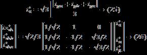
Abovetransformationiscalledclarke'stransformation. NowInverseclarke'stransformationisgivenby

International Research Journal of Engineering and Technology (IRJET) e-ISSN: 2395-0056
Volume: 11 Issue: 10 | Oct 2024 www.irjet.net p-ISSN: 2395-0072
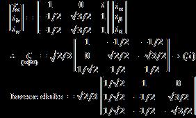
ToDeterminetheCompensationcurrentsforshuntpower Conditioner, the time domain P-q power theory was considered. Since it is implemented in the coordinates, the power grid voltages ( & the loadcurrents( )areconviledto coordinates byapplyingclarke'stransformation


can be either Voltage of current. for3- the coordinates:canbe.expressedas

powertheorycomponents:-


Afterdeterminingvoltage¤tsin coordinates: thePowercomponentsof powertheoryspecifiedas Itisnecessarytoseparateeachpowerintotwocomponents.
(1)Averagevalue
(2)Oscillatingvalue( )
forsuchpurposeadigitallowpassfiltersareused


shunt power conditioner regulates -link vollage ,)Withadditionalvariable whichisadded to If power from RES matches the charging power of the batteries. Then, the operating power of the multiport DC Conditioner intheinterfacewithdc-linkisexpressed as (17)isaddedto(16)

where definestheshuntpowerconditionerinjectsor absorbsactivepower.Consideringthisstrategy,theVIinPV panels( ,ideA)&inbatteries( ,idcb)changeswhile dc-linkvoltage aremaintainedtobecontrolled byshuntcontrollers.

After determining the values of , the instantaneous values that defines the operating reference currents for shunt power conditioner are determined in coordinates.


Oscillatingportionofinstantaneousactivecurrentisonaxis.(-vesignisforcurrentdirection) on -axis

forInstantaneousreactivecurrenton axis axis

International Research Journal of Engineering and Technology (IRJET) e-ISSN: 2395-0056
Volume: 11 Issue: 10 | Oct 2024 www.irjet.net p-ISSN: 2395-0072


Bydoinginverseclarke'stransformation.
To determine the compensation voltages for the series power conditioner, it is necessary to know the nominal voltage(vPLL–a,b,c˝)andthepowergridvoltage(vg–a,b,c˝). Hence,thecompensationvoltagesaredeterminedaccording to
vs
∗ e{a,b,c}= vPLL{a,b,c} vg{a,b,c} .
Duringtheoccurrenceofsagsorswells,thecompensation voltagesareadjustedtomaintaintheloadvoltageswiththe nominalvaluesandsinusoidalwaveform.Therefore,thePLL has an important influence on the convergence of such strategy. Since the power follow can be established in bidirectionalmodebetweentheshuntandtheseriespower conditioner,theloadcanbesuppliedwithnominalvoltages (in frequency and amplitude) in steady-state operation. Moreover,thenecessarypowercanalsobesuppliedbythe energy storage system interfaced by the multiport dc conditioner. To control the series power conditioner to produce this voltage, a strategy is used expressing the voltage produced by the converter as a function of the voltages.Asaresult,itcanbeestablishedas
vs ∗ e{a,b,c}[k]= MA vPLL{a,b,c}[k] vg{a,b,c}[k] vdc1 + vdc2
whereMAistheamplitudeofthemodulatorandvse–a,b,c˝∗ isthesignalthatiscomparedwiththe modulatortoobtain the desired voltage produced by the series power conditioner (measured in the points ase, bse, and cse identified).
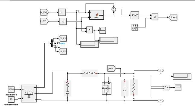
Regardingthemultiportdcconditioner,it'sallaboutefficient power management. This system has two interfaces: one with the RES (solar PV panels, unidirectional power operation) and one with the storage system (batteries, bidirectionalpoweroperation).Theinterfacewiththesolar PV panels utilizes a P&O algorithm to control MPPT operation,ensuringmaximumpowerextraction.Whilethe intricacies of this algorithm are beyond the scope of this article, it's crucial to understand that it enables the extractionofmaximumpowerfromthesolarPVpanels.The control algorithm proposed in this article handles this power, either injecting it into the power grid through the shuntconditionerorstoringitinthebatteries.Keepinmind thatonlynativeDCsourcescanbedirectlyconnectedtothe MO-UPQC.
| Page5 from currents.
The multiport dc conditioner's innovative design dynamically updates the duty cycle and utilizes carrier signals to control the state of the IGBTs. This allows for precisecontrolofeachcurrentwithafrequencythatistwice theswitchingfrequency.DependingonthesolarPV panel voltagelevel,thevoltagevxa1xa2canhavethreedistinctive levels,providingmultilevelandinterleavedoperation.The storage system interface primarily operates on constant current, but alternative methods such as constant voltage chargingandconstantpowerdischargingcanalsobeused. Duringcharginganddischarging,thecurrentcontrolaligns with the power management needs of the external grid, which can receive power from the solar PV panels or the powergrid.Thecurrentcontrolduringthechargingprocess isdefinedby
whiletheCurrentControlduringthedischargingProcessis definedby

International Research Journal of Engineering and Technology (IRJET) e-ISSN: 2395-0056
Volume: 11 Issue: 10 | Oct 2024 www.irjet.net p-ISSN: 2395-0072

-1:Topologyoftheproposedthree-phaseMO-UPQC withmultiportdcinterfaces
4.EXPERIMENTAL VALIDATION OF MULTIOBJECTIVE UNIFIED POWER QUALITY CONDITIONER
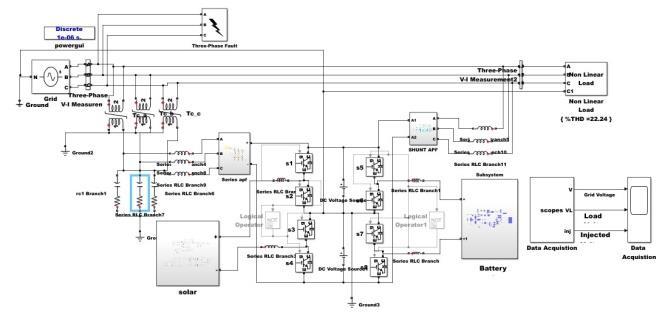
4.1 Simulation Diagrams of MO-UPQC model :Thesystemisbeendesignedandsimulatedasperinfigure2, and the description of the above section is been followedtoexecutethesystemandgettheresults.


4 ShuntActivePowerConditioner

5 BatteryManagementSystem

International Research Journal of Engineering and Technology (IRJET)
Volume: 11 Issue: 10 | Oct 2024 www.irjet.net
This section presents the developed three-phase fourwirelaboratoryprototypeoftheMO-UPQC(10kVA,400V, 50Hz),aswellasthemainexperimentalresultsobtained. Fig.2showsthelaboratoryworkbench,whereitispossible to identify the developed prototype. It is important to highlightthatthisisa preindustrial prototype,andit was experimentally validated connected to the low-voltage power grid, i.e., without any HIL or controlled voltage source,thusvalidatingitsfunctionality.
It is also noteworthy the fact that the equipment was developedfortheintegrationintoanelectricalpanel,ascan beseeninFig.2.Thefollowingmaincomponentswereused: IGBTs model SKM100GB125DN; gate-drivers model SKHI22AH4R; current transducers LA100P; voltage transducers CYHVS025A. For coupling the series conditioner, three individual low-frequency transformers wereused,eachonewithnominalcharacteristicsof230V/ 115V,50Hz.Intermsofcontrol,twoDSPTMS320F28335 wereemployed,oneresponsibleforcontrol-lingtheseries powerconditionerandtheotherresponsibleforcontrolling the shunt power conditioner and the multiport dc conditioner. In terms of switching (fsw) and sampling frequency (fs), the values of 20 kHz and 40 kHz were considered,respectively.Themainparametersofthesystem aresummarizedinTable1
Table -1: MAINPARAMETERSOFTHESYSTEM Parameters
Lsec{a,b,c},
4.2 PERFORMANCE ANALYSIS OF MULTI-OBJECTIVE UNIFIED POWER QUALITY CONDITIONER.

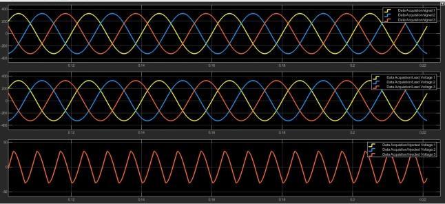
Chart1.showsthesourcevoltageofUPQCduringsagis shown.OnY-axisvoltageisrepresentedandonX-axistimeis represented. InitiallytheUPQC is notworking but when harmonics is generated in the source voltage. In order to mitigatetheseharmonicsofswell,sagetc,TheUPQCstarts working.Thevoltagesaggeneratedat0.9t01p.u.andsource voltagechangesfrom1p.uto1.7.Inordertomaintain1p.uat loadvoltagesomevoltageisinjectedfromUPQC.
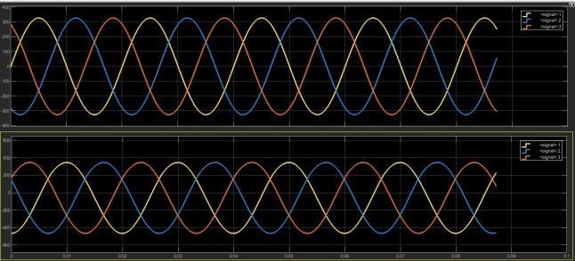
TheChart1showstheinputvoltageandinputcurrentfrom thepowergridwithabalancedsinusoidalwaveforms.The

Volume: 11 Issue: 10 | Oct 2024 www.irjet.net p-ISSN: 2395-0072
voltage of 400v is given to the grid. X-axis represents the timeandY-axisrepresentsthevoltageandcurrent.

OutputofLoadvoltage,Loadcurrentduringsag afterapplicationofUPQC
Inchart3loadvoltageofUPQCisshown.Afteroperationof UPQC the sag from time 0.06 secto 0.12 sec is removed. UPQC removes the voltage sag problems. The total load voltagebecomessinusoidalandgainsitsoriginalmagnitude which is 326 V. The load current of UPQC is contains harmonicsandisnon-linearduetopresenceofnon-linear load. X-axis represents the time and Y-axis represents the voltageandcurrent.

SeriesAPFisusedtomitigateallproblemsrelatedtovoltage unbalanceanddisturbance.Itmitigatethevoltageunbalance insourcevoltagei.e.voltagedip/risesothattheloadvoltage become perfectly balanced and regulated. it is the source voltageduringsag.Sagtimeintervalis0.3secto0.4sec.The sagisduetovoltageunbalancethatmaybecauseddueto faults. The voltage injected by series APF is shown. The injected voltage time interval is 0.3 sec to 0.4 sec. By injectingvoltageinthistimeintervaltheloadsidevoltageis madecompletelybalancedandsinusoidal.TheDCvoltageis constant.X-axisrepresentsthetimeandY-axisrepresents thevoltage.
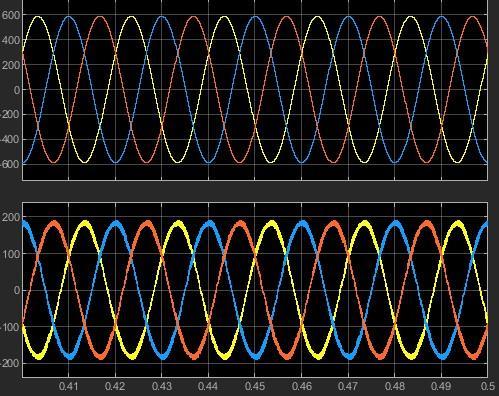
Shunt APF is used to remove problems due to current harmonics. So it makes current drawn from source completely sinusoidal which is effected by load current harmonics. Experimental results of the three-phase shunt powercondi-tionerintransient-stateduringoperationstart, withtheoperationofthebatteriesthroughthemultiportdc conditioner,showingthepowergridcurrents(iga, igb, igc),the voltagesinthedc-link(vdc1, vdc2),andthevoltage(vdcb)and current(idcb)inthebatteries.X-axisrepresentsthetimeand Y-axisrepresentsthevoltageandcurrent.

The series APF part of UPQC is responsible for voltage mitigation.Themagnitudeofloadvoltageisnow326V.the injectedvoltageduringswellconditionisshown.Thevoltage is injected between time interval 0.1 sec to 0.2 sec. After injectingthisvoltagetheloadvoltagebecomescompletely balanced.X-axisrepresentsthetimeandY-axisrepresents thevoltage.
The article introduces a new MO-UPQC, which is different from the traditional unified power quality conditioner. It includes a multiport DC conditioner connected to the commonDC-linkoftheseriesandshuntpowerconditioners, enablinginterfacewithrenewableenergysources(suchas PV panels) and energy storage systems (batteries). The articlethoroughlypresentstheproposedtopology,itsmain principleofoperation,andthedistinctcontrolalgorithmsfor different operation modes, supported by extensive experimentalresults.Theexperimentswereconductedusing a three-phase four-wire laboratory prototype,

International Research Journal of Engineering and Technology (IRJET) e-ISSN: 2395-0056
Volume: 11 Issue: 10 | Oct 2024 www.irjet.net p-ISSN: 2395-0072
demonstrating the effectiveness of power quality compensation for voltage and current harmonics, load voltage and grid current balancing, and reactive power compensation. The bidirectional power operation of the multiportDCconditionerwasalsovalidated,showingpower sharingamongtherenewableenergysource,energystorage system, and power grid through the shunt power conditioner. The experimental results demonstrate the feasibilityofoperatingtheproposedMO-UPQC.Additionally, thearticlesuggestspotentialapplicationsoftheMO-UPQC, suchasservingasanenergybackupsystemduringpower outagesandcoordinatedoperationwiththepowergridfor voltageandfrequencycontrol.Finally,acomparativestudy between the proposed MO-UPQC and conventional structuresispresented.
[1]K. M. Muttaqi, Md. R. Islam, and D. Sutanto, “Future power distribution grids: Integration of renewable energy, energy storage, electric vehicles, superconductor, and magnetic bus,” IEEE Trans. Appl. Supercond.,vol.29,no.2,Mar.2019,Art.no.3800305, doi:10.1109/TASC.2019.2895528
[2]J.E.HuberandJ.W.Kolar,“Applicabilityofsolid-State transformersintoday’sandfuturedistributiongrids,” IEEE Trans. Smart Grid,vol.10,no.1,pp.317–326,Jan. 2019,doi:10.1109/TSG.2017.2738610.
[3]B. Kroposki et al., “Autonomous energy grids,” IEEE Power Energy Mag.,vol.18,no.6,pp.37–46,Nov./Dec. 2020,doi:10.1109/MPE.2020.3014540
[4]D. Lineweber and S. McNulty, “The cost of power disturbances to industrial and digital economy companies,” EPRI CEIDS Consortium for Electric InfrastructuretoSupportaDigitalSociety,pp.1–98,Jun. 2001.
[5]R.TargoszandD.Chapmann,“Thecostofpoorpower quality,”Applica-tionNote-EuropeanCopperInstitueLeonardoEnergy,no.3,May2012.
[6]I. Khan, A. S. Vijay, and S. Doolla, “Nonlinear load harmonic mitigation strategies in microgrids: State of theart,” IEEE Syst. J.,vol.16,no.3,pp.4243–4255,Sep. 2022,doi:10.1109/JSYST.2021.3130612.
[7]H. Akagi, “New trends in active filters for power conditioning,” IEEE Trans. Ind. Appl.,vol.32,no.6,pp. 1312–1322,Nov./Dec.1996,doi:10.1109/28.556633
[8]H. Fujita and H. Akagi, “The unified power quality conditioner:Theintegrationofseriesactivefiltersand shuntactivefilters,” IEEE Trans. Power Electron.,vol.13, no. 2, pp. 315–322, Mar. 1998, doi: 10.1109/PESC.1996.548626
[9]S. K. Dash and P. K. Ray, “A new PV-open-UPQC configura-tionforvoltagesensitiveloadsutilizingnovel adaptivecontrollers,” IEEE Trans. Ind. Inform.,vol.17, no. 1, pp. 421–429, Jan. 2021, doi: 10.1109/TII.2020.2986308
[10]J. Han, X. Li, Y. Jiang, and S. Gong, “Three-phase UPQC topology based on quadruple-active-bridge,” IEEE Access, vol. 9, pp. 4049–4058, Jan. 2021, doi: 10.1109/ACCESS.2020.3047961.
[11]T.S.Prakash,P.S.Kumar,andR.P.S.Chandrasena,“A novelIUPQCformulti-feedersystemsusingmultilevel converters with grid integration of hybrid renewable energysystem,” IEEE Access,vol.8,pp.44903–44912, Mar.2020,doi:10.1109/ACCESS.2020.2977754
[12]P. E. Melín et al., “Analysis, design and control of a unifiedpower-qualityconditionerbasedonacurrentsourcetopology,” IEEE Trans. Power Del.,vol.27,no.4, pp. 1727–1736, Oct. 2012, doi: 10.1109/TPWRD.2012.2199524
[13]V.S.P.Cheung,R.S.C.Yeung,H.S.H.Chung,A.WL.Lo, andW.Wu,“Atransformer-lessunifiedpowerquality conditioner with fast dynamic control,” IEEE Trans. Power Electron.,vol.33,no.5,pp.3926–3937,May2018, doi:10.1109/ECCE.2017.8096545.
[14]Q. Xu, F. Ma, A. Luo, Z. He, and H. Xiao, “Analysis and control of M3C-based UPQC for power quality improvement in medium/high-voltage power grid,” IEEE Trans. Power Electron.,vol.31,no.12, pp.8182–8194,Dec.2016,doi:10.1109/TPEL.2016.2520586
[15]T. Koroglu, A. Tan, M. M. Savrun, M. U. Cuma, K. C. Bayindir, and M. Tumay, “Implementation of a novel hybrid UPQC topology endowed with an isolated bidirectionalDC–DCconverteratDClink,” IEEEJ. Emerg. Sel. Topics Power Electron.,vol.8,no.3,pp.2733–2746, Sep.2020,doi:10.1109/JESTPE.2019.2898369
[16]A.M.Rauf,A.V.Sant,V.Khadkikar,andH.H.Zeineldin, “Anovelten-switchtopologyforunifiedpowerquality conditioner,” IEEE Trans. Power Electron.,vol.31,no.10, pp. 6937–6946, Oct. 2016, doi: 10.1109/TPEL.2015.2509510
[17]R.M.Santos,J.Cunha, and M.Mezaroba,“A simplified con-trol technique for a dual unified power quality conditioner,” IEEE Trans. Ind. Electron.,vol.61,no.11, pp. 5851–5860, Nov. 2014, doi: 10.1109/TIE.2014.2314055.

International Research Journal of Engineering and Technology (IRJET) e-ISSN: 2395-0056
Volume: 11 Issue: 10 | Oct 2024 www.irjet.net p-ISSN: 2395-0072
[18]B. Ambati and V. Khadkikar, “Optimal sizing of UPQC considering VA loading and maximum utilization of power-electronic converters,” IEEE Trans. Power Del., vol. 29, no. 3, pp. 1490–1498, Jun. 2014, doi: 10.1109/TPWRD.2013.2295857
[19]S.B.Karanki,N.Geddada,M.K.Mishra,andB.K.Kumar, “Amodifiedthree-phasefour-wireUPQCtopologywith reduced DC-link voltage rat-ing,” IEEE Trans. Ind. Electron.,vol.60,no.9,pp.3555–3566,Sep.2013,doi: 10.1109/TIE.2012.2206333.
[20]A. K. Giri, S. Arya, and R. Maurya, “Compensation of power quality problems in wind-based renewable energy system for small consumer as isolated loads,” IEEE Trans. Ind. Electron., vol. 66, no. 11, pp. 9023–9031,Nov.2019,doi:10.1109/TIE.2018.2873515
[21]S. Devassy and B. Singh, “Design and performance analysisofthree-phasesolarPVintegratedUPQC,” IEEE Trans. Ind. Appl.,vol.54,no.1, pp. 73–81,Jan.2018,doi:10.1109/TIA.2017.2754983
[22]N. Saxena, I. Hussain, B. Singh, and A. Vyas, “Implementationofagrid-integratedPV-batterysystem forresidentialandelectricalvehicleap-plications,” IEEE Ind. Electron.,vol.65,no.8,pp.6592–6600,Aug.2018, doi:10.1109/TIE.2017.2739712.
[23]V. Rallabandi, O. M. Akeyo, N. Jewell, and D. M. Ionel, “Incorporating battery energy storage systems into multi-MWgridconnectedPVsys-tems,” IEEETrans. Ind. Appl., vol. 55, no. 1, pp. 638–647, Jan. 2019, doi: 10.1109/TIA.2018.2864696
[24]S. R. Ghatak, S. Sannigrahi, and P. Acharjee, “Multiobjectiveapproachforstrategicincorporationofsolar energysource,batterystoragesystem,andDSTATCOM inasmartgridenvironment,” IEEE Syst. J.,vol.13,no.3, pp. 3038–3049, Sep. 2019, doi: 10.1109/JSYST.2018.2875177.
[25]K.K.Prasad,H.Myneni,andG.S.Kumar,“Powerquality improvement and PV Power injection by DSTATCOMWithvariableDClinkvoltagecontrolfrom RSC-MLC,” IEEE Trans. Sustain. Energy,vol.10,no.2, pp. 876–885, Apr. 2019, doi: 10.1109/TSTE.2018.2853192
[26]Q.Liu,Y.Li,L.Luo,Y.Peng,andY.Cao,“Powerquality management of PV Power plant with transformer integratedfilteringmethod,” IEEETrans. PowerDel.,vol. 34, no. 3, pp. 941–949, Jun. 2019, doi: 10.1109/TPWRD.2018.2881991.
[27]L. G. Campanhol, S. O. Silva, A. A. Oliveira, and V. D. Bacon, “Single-stage three-phase grid-tied PV system with universal filter-ing capability applied to DG systems and AC microgrids,” IEEE Trans. Power Electron.,vol.32,no.12,pp.9131–9142,Dec.2017,doi: 10.1109/TPEL.2017.2659381
[28]P. Ray, P. K. Ray, and S. K. Dash, “Power quality enhancement and Power flow analysis of a PV integrated UPQC system in a distribution network,” IEEE Trans. Ind. Appl.,vol.58,no.1,pp.201–211,Jan. 2022,doi:10.1109/TIA.2021.3131404.
[29]S.DevassyandB.Singh,“PerformanceanalysisofSolar PVarrayandbat-teryintegratedunifiedpowerquality conditioner for microgrid systems,” IEEE Trans. Ind. Electron.,vol.68,no.5,pp.4027–4035,May2021,doi: 10.1109/TIE.2020.2984439
[30]J.Wang,K.Sun,H.Wu,J.Zhu,Y.Xing,andY.Li,“Hybrid connectedunifiedpowerqualityconditionerintegrating distributed generation with reduced power capacity andenhancedconversionefficiency,” IEEE Trans. Ind. Electron.,vol.68,no.12,pp.12340–12352,Dec.2021, doi:10.1109/TIE.2020.3040687