
International Research Journal of Engineering and Technology (IRJET) e-ISSN: 2395-0056
Volume: 11 Issue: 10 | Oct 2024 www.irjet.net p-ISSN: 2395-0072


International Research Journal of Engineering and Technology (IRJET) e-ISSN: 2395-0056
Volume: 11 Issue: 10 | Oct 2024 www.irjet.net p-ISSN: 2395-0072
Rishya Shringhan Ravichandran1 , Dr.Bade Shrestha2
1Graduate Research Associate, Department of Mechanical and Aerospace Engineering, Western Michigan University, Kalamazoo, Michigan, USA - 49008
2Professor, Department of Mechanical and Aerospace Engineering, Western Michigan University, Kalamazoo, Michigan, USA - 49008
Abstract - The study focused on simulating the flow channels in Polymer Electrolyte Fuel Cells (PEMFC) under different operating conditions to evaluate their effects on the cell performance. Usinga three-dimensional modelofa PEMFC with a 25cm2 active area, various flow channel designs (single serpentine, bi serpentine, andtriserpentine) were investigated using ANSYS FLUENT software. The obtained results were compared to the experimental data to validate the model. Factors like pressure distribution, and velocity magnitude were examined alongside fuel cell performance. The findings indicated that the tri serpentine flow channel designs exhibited a power density of 0.6655 W/cm2 at 373K while the bi serpentine produced 1.10 %lower, andthe single serpentine yielded 1.15 % lower than the tri serpentine flow channel
1.INTRODUCTION
To help create a more sustainable future, advanced technologiessuchassolar-powered vehiclesandFuel Cell ElectricVehicles(FCEVs)areessentialtoreduceemissions and address global warming. In automotive applications, Researchers are interested in Polymer Electrolyte MembraneFuelCells(PEMFCs)duetotheirhighefficiency, low- temperature operation, high power density, rapid startup, and system durability. The flow channel plays an essential role in PEMFC, facilitating the conveyance of reactantstothe electrodes.Theefficiencyofthetransport processes are determined by the design configurations, dimensions, and patterns, which impact the cell’s overall performance.
StudiesshowsthattheperformanceofPolymerElectrolyte MembraneFuelCells(PEMFCs)canbemodifiedbyadjusting thegeometryoftheflowchannels.Liuetal.[1]developeda computational model to optimize the dimensions of the current collector and the cross-sectional area of the flow channels. The findings revealed that the power output of PEMFCs increased by reducing the total width of the flow channelsandtherib-to-totalwidthratio.Hashemietal.[2] studied the performance of PEMFCs with serpentine and straight flow fields. The results demonstrated that the serpentine flow fields achieved a more uniform current densityandtemperaturedistribution.
Mahammadetal.[3]determinedthattheperformanceof PEMFCs are modulated by the channel dimensions, determining that an optimal rib thickness augments
efficiency. Yousefetal.[4]exploreda Computational Fluid Dynamics(CFD)methodologytoinvestigatetheramifications of novel flow channel design on PEMFC performance, discovering that this innovation design performed better thanconventionalconfigurations.AccordingtoLiuetal.[5], disparategasflowfieldarchitecturesoutcomesincludepintype,single,andmultiplechannels.Iranzoetal[6]utilizeda CFD paradigm with ANSYS Fluent software to compare parallelandserpentineflowfields,explainingthatserpentine configuration conferred superior performance enhancements.Amirinejadetal.[7]analyzedaPEMFCwith anactiveareaof5cm2underassortedoperationalconditions includingtemperature,pressure,andreactantgashumidity–demonstrating that an increase in cell temperature and operatingpressureenhancedperformance.Carcadeetal.[8] investigatedtheimpactofchannelcross-sectionalareaand serpentine channel patterns, concluding that minimizing channel and land width while augmenting the number of serpentine channels yielded superior cell performance at elevatedcurrentdensities.
The research by Santamaria et al [9] involved the distributionofgasinchannelsrangingfrom5cmto25cm.It wasobservedthatthelongerchannelsweremoreeffective than the shorter ones. By simulating PEMFCs through the fluent module, Eker and Taymaz [10] investigated the influenceofflowchannelwidthandoperatingtemperature. The findings revealed that as the flow channel width increased, the fuel cell performance declined when the temperaturedropped.ThestudybySukkeeandWang[11] usingComputationalFluidDynamics(CFD)toanalyzethe3D interaction between straight and interdigitated flow field channels,revealingthatinterdigitatedflowchannelismore efficientatremovingwaterfromthecatalystlayerthanthe straightchannel.ZhongminWanetal.[12]developedanovel M-shapedchanneldesignforPEMFCbipolarplates.Thestudy foundthatbyincreasingtheheightandthicknessofobstacles improvedreactantflowalongthewall,whichenhancedheat andmasstransferandyieldeda21.3%higherpowerdensity withoutadditionalpumpingenergy.
AccordingtoGenevaetal.[13],anextendedflowfieldcan lead to pressure loss, contributing to water flooding and negativelyimpactingPEMFCperformance.Shimpaleeetal. [14] explored the performance of a PEMFC with an active area of 200 cm2 incorporating several configurations of StraightFlowField(SFF).ThefindingsofMahammadetal.

International Research Journal of Engineering and Technology (IRJET) e-ISSN: 2395-0056
Volume: 11 Issue: 10 | Oct 2024 www.irjet.net p-ISSN: 2395-0072
[15]highlightedthatthePEMFCperformanceisaffectedby the size of the channels and the optimal rib thickness contributing to better performance. The research by Roshandel et al. [16] examined a bio-inspired flow field designforPEMfuelcells,featuringaleaf-shapedchannel.The analysisrevealedmoreuniformdistributionofoxygen(O2) concentration, pressure, and velocity distributions than standardflowfielddesigns.Thecurrentdensityincreasedby 26%overserpentinefieldsand56%overparallelfields.By alteringthechanneldepth,Chowdaryetal.[17]developed fourdifferentflowfieldsanddiscoveredthatadecreasein channel depth improved species diffusion in PEMFCs. The workbyAtulKumaretal.[18]focusedonoptimizingtheflow channel shapes and dimensions in the end plates of the serpentineflowfield.Itwasobservedthata9%increasein hydrogen (H2) consumption at the anode contributed to enhancedperformanceofthePEMFC.
Theprimaryaimofthisinvestigationistoevaluatethe performance of Polymer Electrolyte Membrane Fuel Cells (PEMFCs)bymodulatingthegeometricalparametersofthe flowchannelsunder a spectrum of operational conditions. Thisresearchencompassesacomparativeanalysisbetween extant published data and the author’s simulation results. Three novel serpentine flow channel architectures were devisedandsimulatedutilizingtheANSYSFLUENTmodule across varied operational regimes. Critical performance metrics such as pressure distribution, and velocity magnitudeswereanalyzed.Additionally,acomparativestudy wasexecutedbyvaryingthedimensionsoftheflowchannel ribs, subjected to an array of parameters. The outcomes demonstratethatthetri-serpentineconfigurationmanifests superiorperformancerelativetootherdesigns,attributedto its diminished pressure drop. Furthermore, the discourse includesadetailedexaminationofvelocitymagnitudeaswell.
In any Computational Fluid Dynamics (CFD) analysis, validation is a critical aspect. This process involves comparing the simulated data with existing results or experimentaldatatoensureaccuracyandreliability.
In this design, five distinct configurations of the flow channels are examined, integrating both rectangular and slanted channel geometries. To corroborate the fidelity of thesemodels,empiricaldatasourcedfromWawdeeP,etal [19] is leveraged for comparative analysis. The intricate dimensionsand specifications of the experimental PEMFC aresuccinctlydelineatedinTable1.Thearrangementsare detailedinTable2.
Table -1: DetailsoftheexperimentalPEMFC[19]
Cathode
Anode and Cathode GDL
Table -2: Detailsofthevariousconfigurationof experimentalPEMFC[19] RUN ANODE CONFIGURATION CATHODE

1 Rectangular Channel Plate(RP) Rectangular Channel Plate(RP)

2 DownSlanted (ADS) DownSlanted (ADS)
3 UpSlanted(AUS) UpSlanted(AUS)


4 Rectangular Channel Plate(RP) Rectangular Channel Plate(RP)

5 Rectangular Channel Plate(RP) Rectangular Channel Plate(RP)
Thefuelcellunderconsiderationhasanactiveareaof150 cm2. Its flow channel plate was designed with parallel serpentine arrangements featuring primary grooved channels. Specifically, rectangular cross-sectional channels measuring1.5mminwidthand1mmindepthweregrooved onto a conventional graphite flow field. In contrast, the modifiedassistedflowfieldincorporateschannelsslantedat an angle of 35°. The simulation encompasses two distinct temperature353Kand368K,operatingatavoltageof0.5V and 0.7V. The figure 1shows the design of experimental PEMFC.

International Research Journal of Engineering and Technology (IRJET) e-ISSN: 2395-0056
Volume: 11 Issue: 10 | Oct 2024 www.irjet.net p-ISSN: 2395-0072

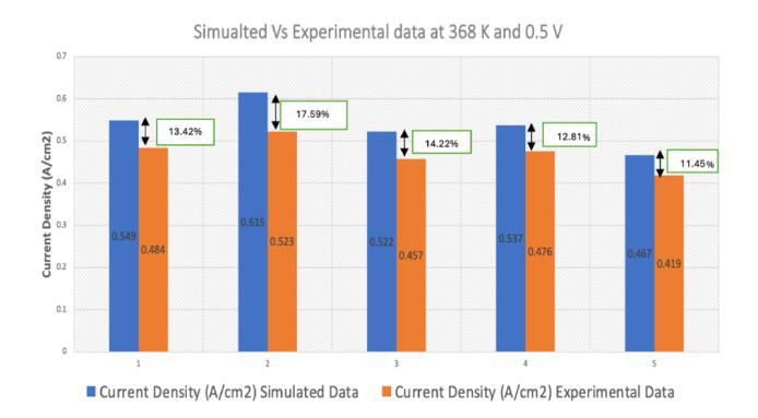
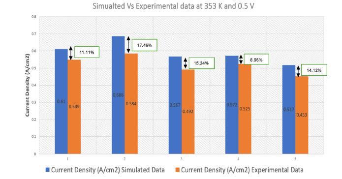
The obtained simulation data were compared with the experimentaldata.Theresultswereslightlyvaryingfromthe experimental data. This variation is due to the differences betweentheexperimentalcircumstances.Forexample,the softwaresimulationconsidersthatthesystemoccurswithno leakage of the substances whereas the experimental had someleakageissues.
Below is a comparison of data analysis conducted at temperatures of 368K (95°C) and 353K (80°C), both at a voltageof0.5Vand0.7V,acrossdifferentconfigurations.
experimental
Figures2and3depictthecomparisonbetweensimulated andexperimentalresultsforallfiveconfigurationsandthe errorswereindicatedatthetopofthegraphineachcase.
The following presents a comparative analysis of data obtainedat368K(95°C)and353K(80°C),specificallyat0.7V acrossdifferentconfigurations.
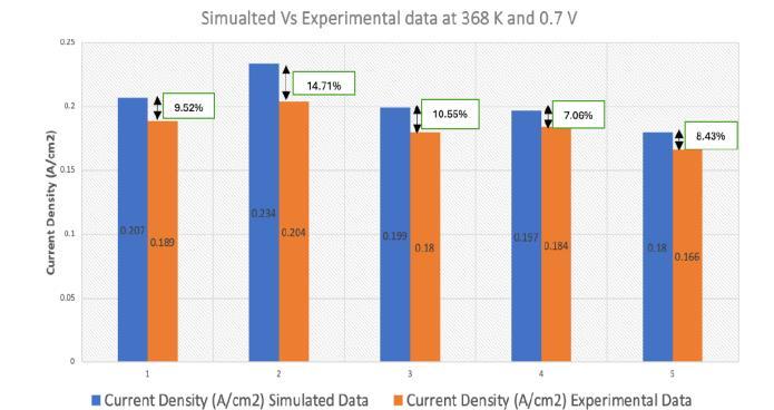
Fig -4:Comparisonofsimulatedandexperimentaldata ofPEMFCin368Ktemperatureat0.7Vvoltage
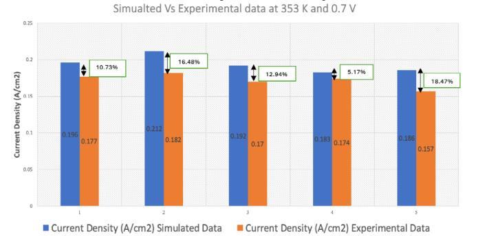
Fig -5:Comparisonofsimulatedandexperimentaldata ofPEMFCin353Ktemperatureat0.7Vvoltage
Figures4and5depictthecomparisonbetweensimulated andexperimentalresultsforallfiveconfigurationsandthe errorswereshownatthetipsofthebargraphs.
Theseresultsindicatethepercentageoferrorsbetween each configuration's simulated and experimental current densities under the specified operating conditions. The results indicate that the current density is inversely proportional to the circuit's voltage drop, given that other factors remain constant. The simulated data were consistently higher because of no leakage of gaseous substances. The comparison shows that the errors are reasonable.
The geometry model was designed using SOLIDWORKS2022software,withspecificzonesdefinedfor modelingdomainslikecurrentcollectors,flowfieldchannels, gas diffusion layers, catalyst layers, and membranes.

International Research Journal of Engineering and Technology (IRJET) e-ISSN: 2395-0056
Volume: 11 Issue: 10 | Oct 2024 www.irjet.net p-ISSN: 2395-0072
Subsequently,thegridwasexportedtoANSYSFLUENT2022 R2licensedsoftwareformeshingandsolvingthecomplete moduleset.ANSYSoffersanadd-onPEMfuelcellmoduleto solve fluid-based equations like Joule heating, electrochemistry, membrane water transport, multiphase, multi-componentdiffusion,andanisotropice-conductivityin porouselectrode,Butler-Volmerrate.Thenumericalmodel represents a single cell geometry employing humidified hydrogenandairasreactantgasesoperatingtemperatures from313Kto373K,withanoperatingpressureof2bar.The opencircuitrangefrom0.1Vto1Vcoveringanactiveareaof 5 cm2 and channel dimensions of 2mm width and depth. Mesh characteristics, geometry properties, and simulation parametersaredetailedintable3,4,and5withmeshquality consistentlymaintainedacrossalldesigns.
Table -3: Thecharacteristicsofthemesh S.No
1 Nodes 1008943
2 Elements 1109348
The corresponding modules necessary for the analysis wereselectedinthesoftware,includingtheflowmodulefor species flow based on specified boundary conditions like pressure and velocity, the species transport module for chemical reactions using the diffusivity matrix, and the current distribution module to determine generated and density corresponding to reactions. A coupled analysis of thesemoduleswereperformed,culminatinginthededuction ofpowerdensityfromthepolarizationcurve.
Table -4: ThegeometricparametersofPEMFC
Anodeand Cathode FlowPlate
Table 4 shows the details of the design of PEMFC and the materialsusedforeachcomponentofthecell
Table -5: Operatingconditionsandrelevantparametersof thestudy[20]
(K)
Massflowrate ofHydrogen (H2)atAnode (Kg/s) 4.33e-07 [20]
3 Massflowrate ofOxygen(O2) atCathode (Kg/s)
4 Anodeinlet temperature (K)
-07 [20]
313/323/333/343/ 353/363/373 Estimated
5 Cathodeinlet temperature (K) 313/323/333/343/ 353/363/373
Operating Pressure(Bar)
[20] 7 OpenCircuit Voltage(V) 0.1,0.15,0.2,0.25, 0.3,0.35,0.4,0.45, 0.5,0.55,0.6,0.65, 0.7,0.75,0.8,0.85, 0.9,0.95,1 Estimated
PorosityofGDL 0.4 Assumed
PorosityofCL 0.5 Assumed
The simulated 3D fuel cell comprises single, bi, and tri serpentinestraightchannels,asdepictedinafigure6,7and8 respectively. Table 4 provides detailed dimensions, while table 5 outlines the operating conditions and relevant parametersusedinthesimulation.Themodelisdeveloped basedonspecificfollowingassumptions.
•ThePolymerElectrolyteMembraneFuelCell(PEMFC)is operated under steady-state conditions, maintaining a constant temperature consistent with its operational parameters
•Simulatedscenariosutilizinghydrogenandoxygenin theirpureform,adheringstrictlytotheprinciplesoftheideal gaslaw

International Research Journal of Engineering and Technology (IRJET) e-ISSN: 2395-0056
Volume: 11 Issue: 10 | Oct 2024 www.irjet.net p-ISSN: 2395-0072
• Gas flow within the channel is constrained to the laminarregime,ensuringapredictableandcontrolledfluid dynamicenvironment
•Theconstituentmaterialsofthecell,includingcatalyst layers,GasDiffusionLayers(GDLs),andthemembrane,are modeledashomogeneousandisotropicentities,essentialfor accuratesimulationresults
•Themembrane’simpermeabilitytogasesisassumed, ensuringnoundesirableleakagecurrentsorgascrossover effects
•Auniformmassflowrateisprescribedatthechannel inlet, maintaining a consistent and controlled flow of reactants
•Thechanneloutletissettoafixedpressure,maintaining equilibrium conditions and ensuring consistency performanceevaluations
The 3 fuel cells with different flow channels are given below. Each fuel cell is varied by the dimension of flow channel. These configurations include a single serpentine flow channel, a bi serpentine flow channel, and a tri serpentine flow channel. Comprehensive design specificationsforthesePolymerElectrolyteMembraneFuel Cells(PEMFCs)areprovidedelaboratelyintable4.
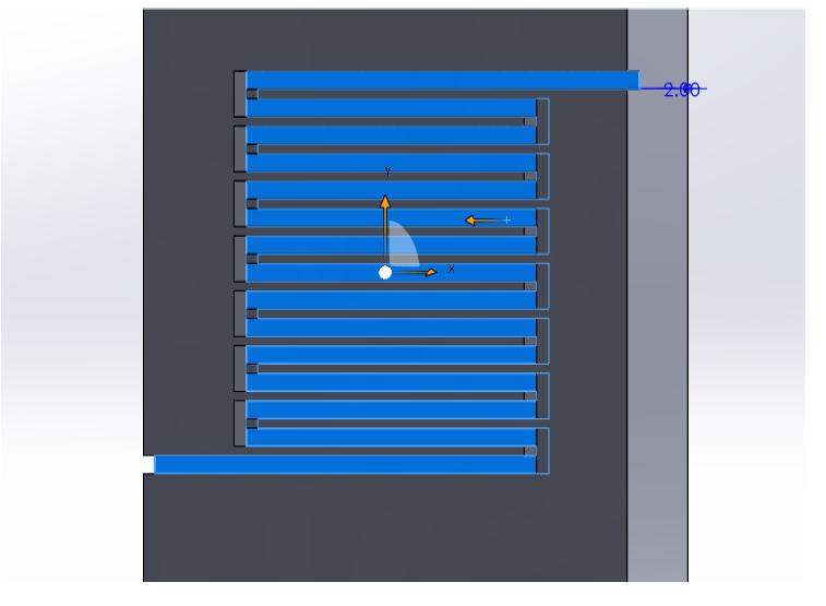
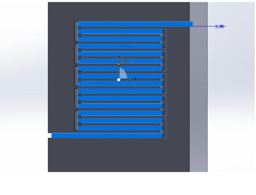

All PEMFC’s are simulated with active area of 25cm2 undervariousparameterswhichhasbeenmentionedintable 5.ThepolarizationcurvegraphfeaturingVoltage(V)along the primary Y-axis, Power Density (W/cm2) along the secondaryY-axis,andCurrentDensity(A/cm2)ontheX-axis is shown in figure 9. This graph comprises three VoltageCurrent(V-I)curvesandthreePower-Current(P-I)curves eachrepresentingtheperformanceofsingle,bi-serpentine, and tri-serpentine flow channel configurations within the PEMFCs.
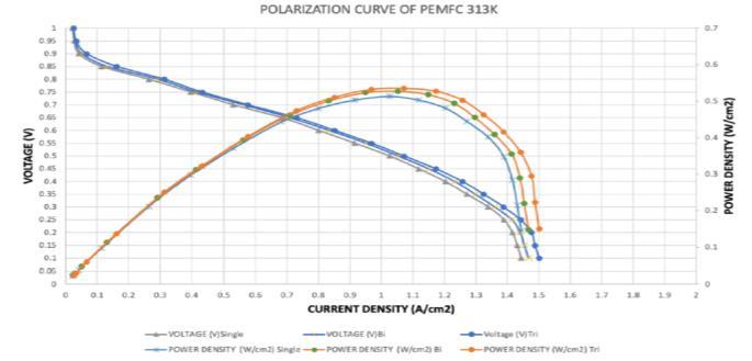
Fig -9:PolarizationcurveofPEMFCat313K(40°C)and2 barpressure

International
Volume: 11 Issue: 10 | Oct 2024 www.irjet.net
Figure9displaysthepolarizationcurveofthePEMFCat 313K(40°C)and2barpressure.Inthesingleserpentineflow channel,themaximumcurrentdensityismeasuredat1.026 A/cm2, yielding a corresponding power density of 0.513 W/cm2 at0.5V.Similarly,inthebi-serpentineflowchannel, the maximumcurrent density is recordedas 1.053 A/cm2 , resultinginapowerdensityof0.5265W/cm2at0.5V.Lastly, in the tri serpentine flow channel, the maximum current densityisdeterminedtobe1.071A/cm2 ,correspondingtoa powerdensityis0.5355W/cm2 at0.5V.
As all polarization curves are similar to figure 9, the resultsfortherestofthetemperatures(323K,333K,343K, 353K,363K,373K)areshownintabularformatintable6.
Table -6: CurrentandPowerDensityofPEMFCat(323K, 333K,343K,353K,363K,373K)and2barpressure
To enhance performance, optimizing pressure distributionisacrucialfactor.Thesimulationiscarriedout across all three designs of flow channels of PEMFC to understand their impact on pressure distribution. The primaryaimistoidentifythestrategiesforimprovingfuel cell performance through effective pressure management. The pressure distribution of the single serpentine flow channel is shown in figure 10 and table 7 explains the pressuredistributionofvariousconfigurationsofPEMFC.For brevity,thefiguresofthebiandtriserpentineflowchannels werenotshown.

International Research Journal of Engineering and Technology (IRJET) e-ISSN: 2395-0056
Volume: 11 Issue: 10 | Oct 2024 www.irjet.net p-ISSN: 2395-0072
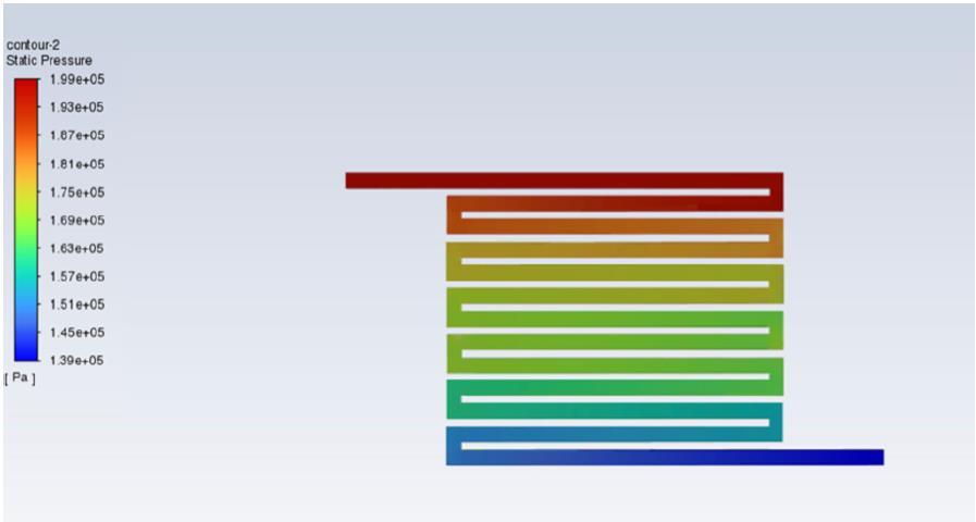
-10:Pressuredistributionof2mmflowchannelwidth ofsingleserpentinePEMFCat0.5V
Table -7: Pressuredistributionof2mmflowchannel widthofvariousconfigurationsofPEMFC
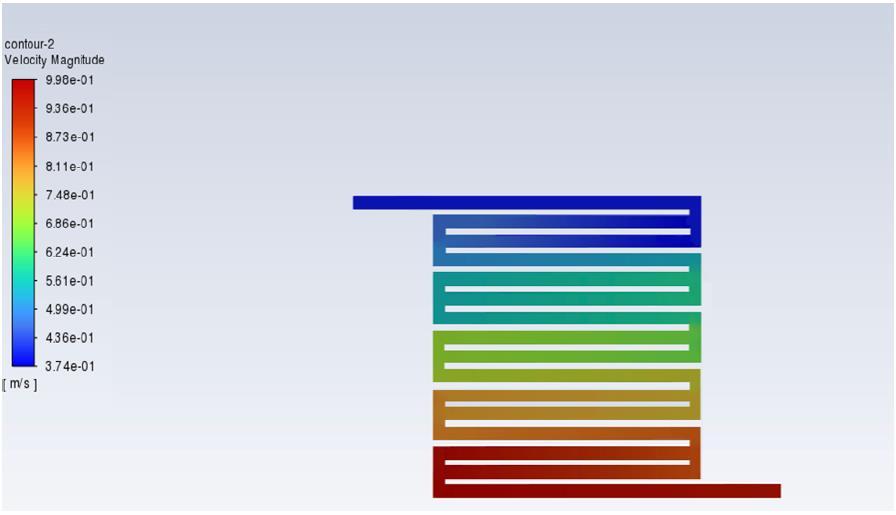
Fig -11:Velocitymagnitudeof2mmflowchannelwidthof biserpentinePEMFCat0.5V
Table -8: Velocitymagnitudeof2mmflowchannelwidth ofvariousconfigurationofPEMFC
N o Flow Chann el Width (mm) Volta ge(V)
1
3
Serpenti
Bi
Despitevariationsinpressuredrop,itisobservedthatthe pressureisdistributedevenlyacrossalldesigns.Thehigher pressuredropinthesingleserpentineflowchannelcanbe attributedtothepresenceofmorebendsinitsdesign,leading to increased resistance and consequent pressure drop. Conversely,thetriserpentinedesignexhibitstheminimum pressuredropduetoitsfewerbends,ultimatelycontributing toimprovedcellperformance.
PEMFC
Velocity magnitude is indeed one of the crucial parameters forassessingthe performance ofPEMFCs. The velocitymagnitudeofallthedifferenttypesofflowchannels are discussed below. The velocity magnitude of the bi serpentine flow channel is shown in figure 14 and table 8 explainsthevelocitymagnitudeofvariousconfigurationsof PEMFC. For brevity, the figures of the single and tri serpentineflowchannelswerenotshown.
The velocity magnitude in the single serpentine flow channel is typically higher due to its straighter design, allowingformoredirectflow.Thisconfigurationoftenresults inefficienttransportofreactantsandbetterperformance.In the bi serpentine flow channel, the velocity magnitude is slightlylowercomparedtothesingleserpentinedesign.This isduetothepresenceofadditionalbendsandtheflowpath, whichreduceoverallvelocity.Thevelocitymagnitudeinthe triserpentineflowchannelisgenerallylowerthanboththe single and bi serpentine designs. While this configuration

International Research Journal of Engineering and Technology (IRJET) e-ISSN: 2395-0056
Volume: 11 Issue: 10 | Oct 2024 www.irjet.net p-ISSN: 2395-0072
offers increased surface area for reactant contact. Furthermore, it is observed that the velocity is evenly distributedthroughouttheflowchannel,confirminguniform flowdistributionacrossoccursalltheregionsofthechannel.
The three models of PEMFC with seven layers namely anodeandcathodeflowchannels,anode,andcathodeGDL, anode and cathode catalyst layers, and membrane were operatedatdifferentcelltemperaturesand2barpressure. ThePEMFCofalldesignswiththecelltemperaturesof313K, 323K, 333K, 343K, 353K, 363K, and 373 K have been analyzed. In single serpentine flow channel PEMFC, the maximum power density was 0.5765 W/cm2 obtained correspondingtothecellpotentialof0.5Vatatemperatureof 373K.Thecorrespondingcurrentdensitywas1.153A/cm2 . Next,thebi-serpentinePEMFCwassimulated.Itisfoundthat the maximum power density was 0.604 W/cm2 obtained correspondingtothecellpotentialof0.5Vatatemperatureof 373K. The corresponding peak current density was 1.208 A/cm2. Finally, the tri-serpentine was analyzed, and the maximum power density was found to be 0.6655W/cm2 obtained corresponding to the cell potential of 0.55V at a temperature of 373K. The corresponding peak current densitywas1.12A/cm2.Thefindingsindicatedthatthetri serpentineflowchanneldesignsexhibitedapowerdensityof 0.6655W/cm2at373Kwhilethebiserpentineproduced1.10 %lowerthantriserpentineandthesingleserpentineyielded 1.15%lowerthantriserpentineflowchannel.
Amongthethreeflowfieldconfigurationsstudied,thetri serpentineflowchannelofferssuperiorperformance,making it the optimal choice for applications that require higher power outputandefficiency.On the other hand,the single serpentineflowchannelexperiencessignificantpressureloss due to the sharp bends, which disrupt the smooth flow of gases,contributingtogreaterenergylossandincreasingfluid resistance, resulting in reduced cell performance. These results illustrate the importance of optimized flow field designtomaintainanefficientanddurablePEMFCoperation.
[1] Liu,H,Li,P,Wang,K.OptimizationofPEMfuelcellflow channeldimensions-Mathematicmodelinganalysisand experimental verification. International Journal of HydrogenEnergy2013;38:9835–9846.
[2] Hashemi, F, Rowshanzamir, S & Rezakazemi, M, “CFD simulation of PEM fuel cell performance: effect of straightandserpentineflowfields,”Mathematicaland ComputerModelling,vol.55,no.3,pp.1540-1557,2014.
[3] M.H. Akbari, B. Rismanchi, Numerical investigation of flowfieldconfigurationandcontactresistanceforPEM
fuelcellperformance,Renew.Energy.33(2008)1775–1783.doi:10.1016/j.renene.2007.10.009.
[4] Yousef,V.;Kurosh,S.Numericalinvestigationofanovel compound flow-field for PEMFC performance improvement.Int.J.Hydrog.Energy2015,40,15032–15039.
[5] Liu, H, Li, P, Juarez-Robles, D, Wang, K & HernandezGuerrero, A, “Experimental study and comparison of variousdesignsofgasflowfieldstoPEMfuelcellsand cellstackperformance,”FrontiersinEnergyResearch, vol.2,no.2.2014.
[6] Iranzo,A,Muñoz,M,Rosa,F&Pino,J,“Numericalmodel fortheperformancepredictionofaPEMfuelcell.Model results and experimental validation,” International JournalofHydrogenEnergy,vol.35,no.20,pp.1153311550,2010.
[7] Amirinejad,M,Rowshanzamir,S&Eikani,MH,“Effects of operating parameters on performance of a proton exchangemembranefuelcell,”JournalofPowerSources, vol.161,no.2,pp.872-875,2006.
[8] Carcadea,E,Ismail,MS,Ingham,DB,Patularu,L,Schitea, D,Marinoiu,A,Ebrasu,DI,Mocanu,D,Varlam,M.Effects ofgeometricaldimensionsofflowchannelsofa largeactive-area PEM fuel cell: A CFD study. International Journal of Hydrogen Energy 2021; 46(25): 1357213582.
[9] A.D. Santamaria, N.J. Cooper, M.K. Becton, J.W. Park, Effect of channel length on interdigitated flow-field PEMFCperformance:Acomputationalandexperimental study, Int.J.HydrogenEnergy38(36)(2013)16253–16263.
[10] E. Eker, I. Taymaz, “Akış kanalı genişliğinin pem tipi yakit hücresi performansınaetkisinin incelenmesi, ”SakaryaUniversitiyFenBilimleriDergisi,2013.
[11] Um, S.; Wang, C.Y. Three-dimensional analysis of transport and electrochemical reactions in polymer electrolytefuelcells.J.PowerSources2004,125,40–51.
[12] Wan,Z.;Quan,W.;Yang,C.;Yan,H.;Chen,X.;Huang,T.; Wang, X.D.; Chan, S. Optimal design of a novel M-like channelinbipolarplatesofprotonexchangemembrane fuelcellbasedonminimumentropygeneration.Energy Convers.Manag.2020,205,112386.
[13] T. Geneve, J. Regnier, C. Turpin, Fuel cell flooding diagnosisbasedontime-constantspectrumanalysis,Int. J.HydrogenEnergy41(1)(2015)516–523.
[14] S. Shimpalee, S. Greenway, J.W.V. Zee, The impact of channel path length on PEMFC flow-field design, J. PowerSources160(1)(2006)398–406.

International Research Journal of Engineering and Technology (IRJET) e-ISSN: 2395-0056
Volume: 11 Issue: 10 | Oct 2024 www.irjet.net p-ISSN: 2395-0072
[15] M.H. Akbari, B. Rismanchi, Numerical investigation of flowfieldconfigurationandcontactresistanceforPEM fuelcellperformance,Renew.Energy.33(2008)1775–1783.doi:10.1016/j.renene.2007.10.009.
[16] Roshandel,R.;Arbabi,F.;Moghaddam,G.K.Simulationof aninnovativeflow-fielddesignbasedonabio-inspired patternforPEMfuelcells.Renew.Energy2012,41,86–95.
[17] Chowdhury, M.Z.; Akansu, Y.E. Novel convergentdivergentserpentineflowfieldseffectonPEMfuelcell performance.Int.J.HydrogenEnergy2017,42,25686–25694.
[18] Atul Kumar, Ramana Reddy. G, Effect of flow channel dimensionsandshapeintheflowfielddistributoronthe performance of polymer electrolyte membrane fuel cells,J.PowerSources,113(2003)pp.11-18.
[19] WawdeeP,etal.,WatertransportinaPEMfuelcellwith slantedchannelflowfieldplates,InternationalJournalof HydrogenEnergy(2015).
[20] Vivek R, Muthukumar M (2018) Performance ImprovementofProtonExchangeMembraneFuelCell. InnovEnerRes7:203.