
International Research Journal of Engineering and Technology (IRJET) e-ISSN:2395-0056
Volume: 11 Issue: 10 | Oct 2024 www.irjet.net p-ISSN:2395-0072


International Research Journal of Engineering and Technology (IRJET) e-ISSN:2395-0056
Volume: 11 Issue: 10 | Oct 2024 www.irjet.net p-ISSN:2395-0072
Rajesh G1 , Prakash M2, Mariappan A C3, Peter Packiaraj G4
1,2Rajesh G, Prakash M, Final Year BE Marine Cadets, PSN CET, Tirunelveli, Tamil Nadu 3,4Assistant Professor, Dept of Marine Engineering, PSN CET, Tirunelveli, Tamil Nadu
1. ABSTRACT
An air lubricating system (ALS) is a technology used primarily in maritime vessels to reduce friction of the vessels hull in the sea water hence, enhancing fuel economy and reduce emission the system works by generating and injecting a layer of air bubbles besides the hull's surface, creating a thin, insulating layer those minimizes direct contact to the water and the vessels hull. This air layer significantly decreases hydrodynamic drag, let the vessel to pass more effective in the water. The system typically includes components like compressors, air distribution units, and control systems to manage the generationandflowofairbubbles.Byreducingfrictionair lubricating systems can lead to substantial fuel savings and lower operational costs, contributing to more sustainablemaritime operation.
Keywords: Air Lubricating System (ALS), Silverstream technology, Mitsubishi Technology, Air Layer Energy SavingSystem(ALES),MAN8L32/44CREngine
2. INTRODUCTION
2-1 Air Injection Unit:
In this strategically placed along the hull, especially at thebottom.Theyreleaseacontrolledflowofair,forming acarpetofmicro-bubblesthatcoatsthehullsurface.
2-2 Bubble Formation and eject:Theinjectedairforms small bubbles that spread through the hull, it creating a thin air coating that minimizes direct contact with the hull and sea water. The even separation of bubbles is crucialformaintaininganeffectivelubricatinglayer.
2-3 Hull Design and Modifications: The hull of ships equipped with air lubrication systems may be designed ormodifiedtooptimizethe effectivenessoftheairlayer. Thisincludesshapingthehulltoensurethatbubblesare evenly distributed and maintained during the ship's operation.
2-4 Control and Monitoring Systems: Sensors and control systems monitor the bubblelayerandadjust the air flow as necessary to maintain optimal lubrication undervaryingseaconditionsandspeeds.
The air lubricating system (ALS) in ships is a cuttingedge technologyaimed at enhancing maritime efficiency by reducing hydrodynamic drag into the ship's hull and seawater.Thissystemintroducesacontrolled coatingof air bubbles beneath the hull, which acts as a lubricant, therebyminimizingresistanceastheshipmovesthrough thewater.
This solution has emerged as a significant idea of the marineindustry,wherefueleconomyandenvironmental impact are major concerns. By decreasing the frictional resistance, an air lubricating system helps in lowering fuel usage, decreasing the construct cost, and cutting downonco2emission
The ALS is particularly relevant in the context of increasinglystringentenvironmentalregulationsandthe rising costs of marine fuel. As the industry seeks sustainable solutions to meet these challenges, the adoption of air lubricating systems offers a promising pathwaytoachievinggreaterfuelefficiencyandreducing the carbon footprint of maritime operations. This introduction of ALS represents solution make global shipping more environmentally and economicallysustainable.
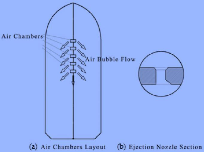
An air ejects in air blow-off portion mounted on the bottom of the hull and the air bubbles flow covers the bottomofthehull

International Research Journal of Engineering and Technology (IRJET) e-ISSN:2395-0056
Volume: 11 Issue: 10 | Oct 2024 www.irjet.net p-ISSN:2395-0072
It is the best solution of ship’s hull which breaks down into micro-bubbles, around 0.1 mm. By adding bubbles toaliquid,thedensityoftheliquiddecreasesandhence the Reynolds number decreases they are some example MitsubishiAirLubrication(MALS),SilverstreamSystems. AirLayerEnergySavingSystem(ALESS),
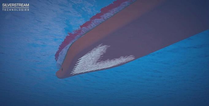
We should emphasize the importance of the injection zones and the injector design. Many companies have created various formations and types of injectors, and this topic demands further 3D computation research in order to optimize the air injection and the bubble generator Figure 2 and Figure 3 show the injection fabrication that was chosen by Silverstream Technology [17]andMitsubishiHeavyIndustries[5].

3-2 The
A water line pipe is fitted to the upper portion of the arena, where its fitted point is offset by 200 mm away fromthecentreofthearena.Onthelowerportionofthe arena are installed sixteen small apertures from which airisblownoff.

Figure 4. showsanoverviewphotographofthechamber. Acommunicationpipeconnectedtotheairsupplypipeis connectedtothetoppartofthechamber,whereitis Attachpointisoffsetby200mmthecentreofthe chamber.Therearesixteensmallholesinthelowerpart ofthechamberthroughwhichaircomesout

Apicture oftheair blow-off condition withthechamber placedunderwater
3.2 Flow velocity distribution test in the air
As shown in Figure 6 is a single pipe, the air blow-off rates from the various holes in the arena grow unbalanced. To correct this phenomenon, baffle boards are installed in the chambers to equalizetheairflow. Figure 5 shows the measurements of flow velocity distributioninthecaseofwithbaffleboardandnobaffle board. The tests were conducted in the air. Model6531 was used to measure flow velocity. In the case of “no baffleboard,”thepeakflowvelocityoccurredaroundthe holebeforesupplyairpipesoalltheaircanblowawayat this point, causing flow velocity distribution to be unequal. In the case of "with baffle board", the flow velocity distribution appeared to be equalized in the longitudinaldirectionRoom
3-4 Underwater air blow-off condition measurement
A model with small holes in the bottom was placed in a watertank.Airflowconditionsfromtherespectiveholes wereobservedbyanunderwatercamera.Figure5shows theexperimentconditions

International Research Journal of Engineering and Technology (IRJET) e-ISSN:2395-0056
Volume: 11 Issue: 10 | Oct 2024 www.irjet.net p-ISSN:2395-0072

Figure 6. A comparative chart of the flow-velocity distribution through the orifices of the chamber blown out
InthecaseofNOBAFFLEBOARD,thepeakflowvelocity occursatthenumbernineandnumbernineandnumber ten apertures and in the case of WITH BAFFEL BOARD, theflowvelocitiesareequalized
3-5 A picture of the air blow-off condition from the apertures (horizontal condition)
Figure 7. A picture of the air blow-off condition from the aperture (horizontal condition)
When the chamber is placed longitudinally a picture of the air flow position is visible from the corresponding aperture Horizontal, taken by an underwater camera. With the chamber being kept exactly horizontal longitudinally, the air blowing into the water is collectedatthebottom of chamber, so as to avoid air accumulation The chamber is tilted laterally by ten degreesforexit. Accordingly, when the chamber is kept longitudinallyhorizontal,air passesuniformlyleft inthe 16holes
Figure 9 showsthepiping diagram.Airdischargedfrom blowersistemporarilystoredin16pipesarefittedtothe head tank are piped to the air pipes are fitted in the lowerofthehull.Anairsupplypipeiseachconnectedto onechamber(airchamber).
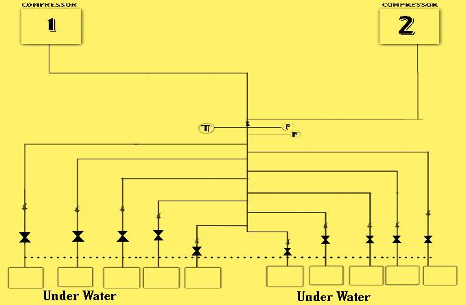
Figure 9. A simple pipe diagram of the air lubrication system (ALS)
Airdischargedfromtwosetofcompressorsisconnected in large diameter pipe and then is distributed to fifteen branchpipestobedeliveredtoairchambermountedon thebottomofthehull
4-1 Representation of an integrated system in ship

Figure 10. It presents the main parts of that synthesize the total air lubrication system. The operation is controlled in the automation room, there wecan set the variablesandcheckthesysteminrealtime
4-2 Suitable compressor type and piping
Compressors use atmospheric air and deliver it through piping systems to air release units. A main pipe distributesthecompressed airinto smaller pipes, which end upatinjectors. This compresoor, takes 160 kW, weighsaround2tons,andprovidesthepipesystemwith maximum 27.8 m3/min of compressed air. The compressorisalsoseawatercooled.

International Research Journal of Engineering and Technology (IRJET) e-ISSN:2395-0056
Volume: 11 Issue: 10 | Oct 2024 www.irjet.net p-ISSN:2395-0072


4-3 Simulation of the flow seawater and bubbles
Astreamlineanimationsnapshotexplainstheprocedure, as the small air pieces (blue colour) are mixed with the passing seawater flow (yellow colour) at the airlubricating areas. The move from left to right, indicate theshiptravelsintheleftdirectionoftheflowingfield.
4-4 Engine features and fuel consumption
AnMAN 8L32/44CR engine isa 13000kw power output and600RPM
Table 1. Outline of the engine being tested
EngineModel MAN8L32/44CR
Configuration 8cylindersinline
Poweroutput 13,000kw(13MW)
Bore 320mm
Stroke 440mm
RPM 600RPM
Displacement 11.32Literspercylinder
Meaneffectivepressure 25.8bar
Compressionratio 15:1
Fueltype
Heavy fuel oil (HFO) Diesel oil(DO)
Weight 155tonswithoutAE
Dimensions(L×W×H) 8meters×3meter×4meter
4-5 Calculate the fuel consumption of this engine
Let’stheMAN8L32/44CRengineconsumesaround 200 tons of fuel per day without air lubrication. In this estimate of the engine reduce the 10% of the fuel. 10% savings:20tons/day
Theairlubricationsystem(ALS)ina ship'shull isan innovative technology designed to enhance the vessel's fuel efficiency and reduce environmental impact. By injecting a layer of air bubbles along the hull, the system effectively reduces frictional resistancetothehullandthewater
TheprimaryadvantageofALSisthereductionofhull resistance,whichlowerstheamountofenginepower required to maintain a given speed. This improvement in fuel efficiencycanlead to significant savings in fuel consumption, making the system economically beneficial over time. The decrease in fuelconsumptiondirectlytranslatestoareductionin CO2 emissions, supporting efforts to meet stringent international regulations on greenhouse gas emissions in the maritime industry. The technology contributes to more sustainable shipping operations. AlthoughtheinitialinstallationofanALSmayinvolve capitalcosts,thelong-termsavingsfromreducedfuel consumption can offset these costs, making it a financiallyviableinvestment.
Additionally, it may help ship operators avoid penalties related to environmental regulations. ALS can be adapted to various types of vessels and operating conditions. Its performance can be optimized based on the ship's speed, load, and sea conditions, ensuring consistent benefits across differentvoyages.
The ALS requires regular maintenance to ensure optimal performance. However, when properly maintained, the system is reliable and can consistently deliver the expected reductions in fuel consumptionandemissions.

International Research Journal of Engineering and Technology (IRJET) e-ISSN:2395-0056
Volume: 11 Issue: 10 | Oct 2024 www.irjet.net p-ISSN:2395-0072
1.Atlar, M., et al. (2013). "An Investigation into the Effect ofAirLubricationTechnologyonShipResistance."Ocean Engineering66,pp.1-12.
2. Goncalves, R.T., Kawamura, H., & Murai, Y. (2010). "EvaluationofDragReductionbyAirLayeronaShipHull with Air Cavity System." Journal of Fluid Mechanics, 666,pp.180-206.
3. Kumar, S. (2015). "Efficiency Improvement by Air Lubrication in Ship Hull." Journal of Marine Engineering andTechnology,14(3),pp.1-8.
4. Makiharju, S. A., Ceccio, S. L., & Perlin, M. (2012). "Time-resolved Skin-friction Measurements on an AirlubricatedFlatPlate."
5.Hori,M.,Ouchi, K., Oka,T.,&Takahashi,T.(2006)."Air LubricationMethodforReducingFrictionalResistanceof Actual Hulls." Journal of Marine Science and Technology, 11(2),pp.94-102.
BIOGRAPHIES:




I am pursuing B.E final year Marine Engineering cadet at PSN College of Engineering & Technology, Tirunelveli,TamilNadu.
I am pursuing B.E final year Marine Engineering cadet at PSN College of Engineering & Technology, Tirunelveli, TamilNadu
Project Guide cum Assistant Professor
PSN College of Engineering & Technology, Tirunelveli, Tamil Nadu. Also having 15 years’ experience in Oil and Gas industries. Specialization in NDT and worked varies Gulf Countries
Project Guide cum Assistant Professor
PSN College of Engineering & Technology, Tirunelveli, Tamil Nadu. MEO Class-IV Marine Engineer and workedvariesCountries