
International Research Journal of Engineering and Technology (IRJET) e-ISSN: 2395-0056
Volume: 11 Issue: 10 | Oct 2024 www.irjet.net p-ISSN: 2395-0072

International Research Journal of Engineering and Technology (IRJET) e-ISSN: 2395-0056
Volume: 11 Issue: 10 | Oct 2024 www.irjet.net p-ISSN: 2395-0072
Le Thi Bich Nam
School of Mechanical Engineering, Hanoi University of Science and Technology, No.1 Dai Co Viet Road, Hanoi, Vietnam
Abstract - Previous studies on the mechanical behavior of artificialhip joints havefocusedonstandardjoints,whichonly allowed the movement of the head in the liner. The finite element method was used to investigate a part of the joint assembly in different patient activities. In this study, the finite element method was effectively used to investigate the mechanical behavior of the dual mobility hip joint, which is a type of joint that allows for more extensive joint degree movements. The mechanical behaviors investigated include the equivalent Von-Mises stress, the total deformation, the total displacement, the contact pressure, and the sliding distance inhumanactivities suchasdailywalkinganddifficult positions such as sitting on a chair or sitting on the floor. Additionally, the materials used to manufacture hip joints have been expanded to include biomaterial with strength equivalent to human bones, such as CF-PEEK plastic, in addition to materials commonly used for hip joints such as Cobalt-Chrome, Titanium, etc.
Key Words: Artificial hip joint, Implant, Human activities, Mechanical behaviour of AHJ, Sliding distance, Finite element method, Biomaterial
The hip joint plays a crucial role in supporting the body's weightduringdailyactivities,connectingthelowerlimbsto thespine,andtransmittingforcefromthegroundtothetop. The need for artificial hip joint (AHJ) replacement is increasing, with elderly individuals suffering from joint diseaseordeformities,aswellasyoungerindividualsdueto vigorous activities or accidents. The main reasons for hip replacementincludeosteoarthritis,fractures,andchangesin bone structure and connective tissue, leading to loss of motorfunctionandpain.
Afterhipreplacementsurgery,issuessuchasjointslippage, frictionbetweenjointpartscausingwear,andthereleaseof metal particles into the body need to be considered. Additionally, the durability and longevity of the artificial joint during the patient's activities and overtime are important factors. Previous studies have used metallic materialsforhipjoints,butthesehavedrawbackssuchas incompatibilitywiththehumanbodyandobstructioninXrays.Toaddresstheseissues,theuseofplasticslikeHDPE fortheLinerandPEEKfortheStemandCupofartificialhip joints has been explored. These materials offer
biocompatibility and transparency in X-rays or CT scans, allowing for more accurate assessments. When PEEK is reinforcedwithcarbonfiber,itcanmatchthestrengthand stiffnessofnaturalhumanbone,preventingstressimbalance withsurroundingboneandensuringevenforcedistribution. Stemmadefrom PEEKmaterial toincreasethebondwith bone, it is necessary to use more bio-cement or add HA coating by Plasma coating method. Nowadays, PEEK-CF materialisgraduallyreplacingTitaniuminitsapplications [5]. In this research, parts of AHJ made of metal (Cobanchrome,Titanium)andCF-PEEKareinvestigated.
Thefiniteelementmethod(FEM)isanessentialmechanical analysismethodusedtoevaluatemechanicalbehaviourof the artificial hip joint. It is used to simulate the effects of motionandloadingonartificialjoints.Al-Shammari[9]used FEM to study a standard hip joint model, investigating different angles of the stem to find the optimal angles of implants,andinvestigatingthemechanicalbehaviourofAHJ madeofaluminiumandCoCralloymaterialsinthenormal walkingpostureofthepatient.EkoSaputraaetal.[3]also used FEM to investigate the stress in the Liner and Head assemblyindifferentsittingposturesofthepatientincluding sittingonachair,squatting,kneeling,andbowing.
Previousstudieshavemainlyfocusedonstandardhipjoints oronlyexaminedspecificpartsofthehipassembly[9],such asthecontactbetweenthelinerandthehead,orthecupliner contact [3]. This study extends the investigation of mechanicalbehaviourtothedualmobilityhipjoint,atypeof hipdesignedtospreadmotionangles.Thedualmobilityhip allowstwomotions:theHeadcanmoveintheLinerandthe Liner can move in the acetabular Cup. As a result, this implant has the potential to reduce the risk of dislocation andimprovejointstability, makingitsuitableforyounger patients with a wide range of movements. Most of the patient's movement postures in daily life were surveyed, including standing, sitting on chairs, and sitting on the ground. The mechanical behaviours that were studied includedstressdistribution,deformationdistribution,and displacementdistributiononthejointdetails.Additionally, the study also examined the contact pressure and sliding distancebetweenthearticulatingparts.
International Research Journal of Engineering and Technology (IRJET) e-ISSN: 2395-0056
Volume: 11 Issue: 10 | Oct 2024 www.irjet.net p-ISSN: 2395-0072
1.1
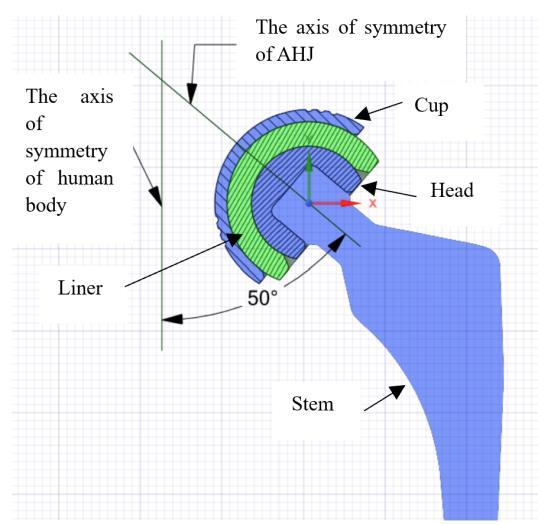
Thedualmobilityartificialhipjointconsistsoffourparts: theCup,Liner,Head,andStem(refertoFig.1).Thegeometry dimensions can be found in Table 1, and the angle of the Stem is 50 degrees. The artificial hip joint is made of two groupsofmaterialsasshowninTable2,withtheproperty parameters of the materials outlined in Table 3. The geometrydimensionsinTable1,theangleoftheStemis50 degrees.TheAHJismadeoftwogroupsofmaterialsshown inTable2,withpropertyparametersofmaterialsinTable3.
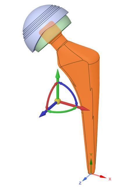
b)
-1: Thedualmobilityhipjointmodeling
Table -1: Geometryparametersoftheartificialhipjoint
Table 2: Materialsmadeofthehipjoint
Materialgroups Cup Liner Stem
Table -3: Materialproperties

Inthisstudy,wewillanalyzethevariousactiveposturesof thepatienttounderstandhowforceimpactsthehipjointin thosepositions.Thepatient'severydayactiveposturestobe examined include normal walking, sitting on a chair, and sittingontheground.Therotationanglesofthehipjointwill change with each posture, and these rotation angles are illustratedintheFigure2.
International Research Journal of Engineering and Technology (IRJET) e-ISSN: 2395-0056
Volume: 11 Issue: 10 | Oct 2024 www.irjet.net p-ISSN: 2395-0072
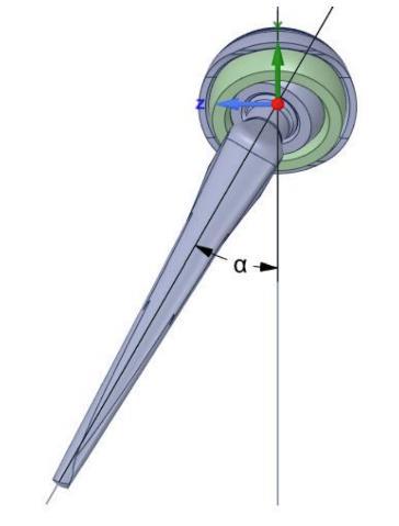
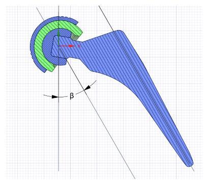
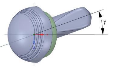
Figure -2: Definethehipjointangles
Theanglesofhipjointrotationincludethreerotationangles around three axes (Fig.2): swinging the leg forward and backward(flexionandextension),movingthelegoutward andinward(abductionandadduction),androtatingtheleg aroundthejoint(externalandinternalrotation).Innormal walking, you have standing, moving forward, and moving backward.Whensittingonachair,youhavetheposturesof pickingupanobject,gettingupfromthechair,andsitting down.Whensittingontheground,youcanbowwithyour legsfullyflexedattheknee,squat,andkneel.Thevaluesof therotationanglesofthehipjointineachposturearelisted in Table 4. In which sitting postures have larger joint movementanglesthannormalwalkingpostures.
Table -4: Hipjointanglesforhumanactivities[3],[9]
Human Activities Flexion/ Extension (α) Adduction/ Abduction (β) Internal /External rotation (γ)
Walking Standing Forward Backward -
Sitonthechair
Pickingupan objectwhile sittingonthe chair
Gettingupfrom thechair
Sittingdownon thechair
Sittingontheground
Bowingwhile sittingonlegs fullyflexedat theknee
Squatting
Kneeling
The mechanical behavior of the present dual mobility hip joint will be investigated using the FEM method by Ansys software. Corresponding to each patient's posture is a correspondingsetofhipjointdegrees.Assumingtheweight ofthebodyandtheweightcarriedis3240N,thepressureon theCupsurfacewillbecalculatedasfollows:
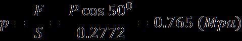
Table -5: Coefficientsofmaterials
Contacts Materials Fictioncoefficient
Cup-liner Cobanchrome/HDPE 0.1
Liner-Head HDPE/Ti6Al4V 0.1
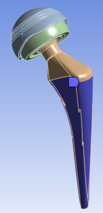
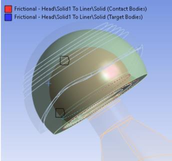
Thestemispress-fittedinsidethefemursothatapartofthe stemwillbefixed(Fig.3).Thecontactofthelinerinsidethe cupandtheheadinsidethelinerwillbeconsideredfriction contact. The coefficients of friction corresponding to the materialsofthecup,head,andlineraregivenintable5.The headisfixedwiththestem.
International Research Journal of Engineering and Technology (IRJET) e-ISSN: 2395-0056
Volume: 11 Issue: 10 | Oct 2024 www.irjet.net p-ISSN: 2395-0072
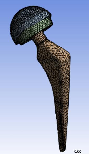
- 4: ThefiniteelementmeshingoftheAHJ
Aftersettingtheboundaryconditionsandapplyingtheforce totheimplant,themeshingstepwillbeperformedwithan initial mesh size of 2mm, Tetra element type, with 24788 elements (Fig.4). To evaluate the convergence of the obtainedresults,theresultsoftheStructureerroranalysis and the automatic convergence meshing are used. For example,whenusingtheautomaticconvergencemeshingto evaluate the convergence of the equivalent stress and the slidingdistanceonthestempartinthebowingposition,the numberof nodesincreased from 44316 to399299, which gaveconvergentresults(Fig.5)
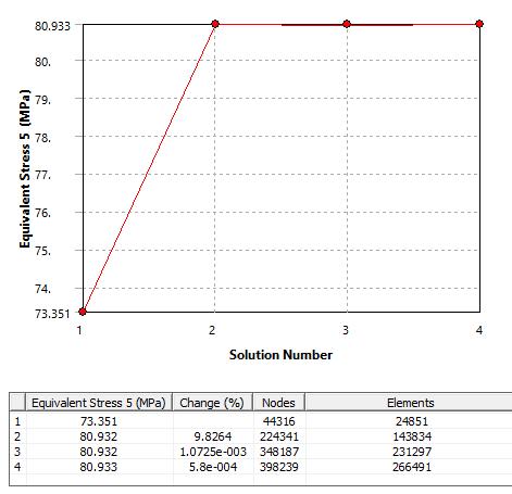
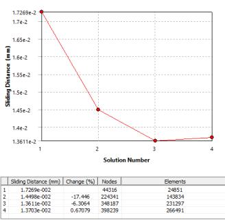
-5: Theconvergenceresultsintheequivalent stressandtheslidingdistance
3.1 The equivalent stress and total strain in the AHJ.
The results for Von-Mises equivalent stresses, maximum total deformations, and maximum total strains in the implants for each position, with group of Material 1 are provided in Tables 6 to 8. In all the cases examined, the higheststresswasobservedonthestem,followedbythecup andthehead,withtheloweststressontheliner.Meanwhile, thelargestdeformationanddisplacementweremainlyon theliner.Itcanbeseenfromthetablesthatsittingpositions with a chair or sitting on the ground result in higher maximumstress(rangingfrom65.591MPato85.729MPa) compared to the normal walking position (ranging from 32.602 MPa to 51.277 MPa). Among the sitting positions, bowing whilesitting on legs fullyflexedat the knee isthe most dangerous, and among the walking positions, the forward has more stress on the stem, which is also a common movement posture of the patient. Total displacementandequivalentstressinthemostdangerous case-bowingwhilesittingonlegsfullyflexedatthekneeare givenindetail inFigure6toFigure15.Thehighest stress occurs at the front of the neck stem in all postures. The upperneckareabearsthemostforce,whilethelowerarea attached to the bone experiences less stress. As a result, whenthepatientwalks,thestemdoesn'tputmuchforceon thebone-joiningposition.
Next,weexaminethemechanicalbehavioroftheabovehip joint made from a group of material 2 with the regular positions being standing and forward and the dangerous positionsbeingbowing(Table9).Weseethatthestressdoes notchangemuchcomparedtothecaseofmaterial1,butthe deformationanddisplacementincreaserelatively.
International Research Journal of Engineering and Technology (IRJET) e-ISSN:
Volume: 11 Issue: 10 | Oct 2024 www.irjet.net
Table -6: Equivalentstresses,max
Table -8: Equivalentstresses,maxtotaldeformationand maxtotalstrainofAHJinsittingongroundpostures, Material1
Pic
Table -7: Equivalentstresses,maxtotaldeformationand maxtotalstrainofAHJinsittingonchairpostures, Material1 Pa rts
Table -9: Equivalentstresses,maxtotaldeformationand maxtotalstrainofAHJinpostures:standing,forward,and bowingwhilesittingonlegsfullyflexedattheknee, Material2
International Research Journal of Engineering and Technology (IRJET) e-ISSN: 2395-0056
Volume: 11 Issue: 10 | Oct 2024 www.irjet.net p-ISSN: 2395-0072
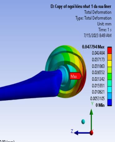
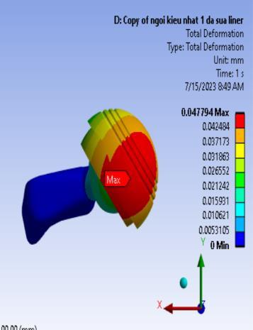
Figure -6: ThetotaldisplacementdistributionontheAHJ inBowingwhilesittingonlegsfullyflexedattheknee position,Material1
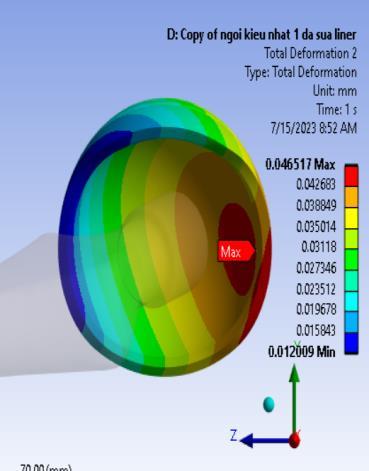
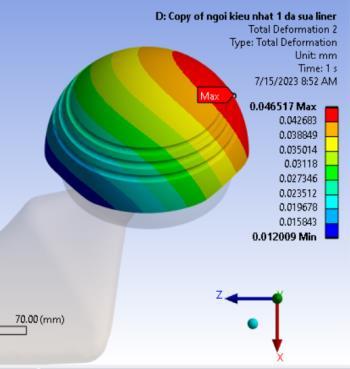
Figure -7: ThetotaldisplacementdistributionontheCup inBowingwhilesittingonlegsfullyflexedattheknee position,Material1
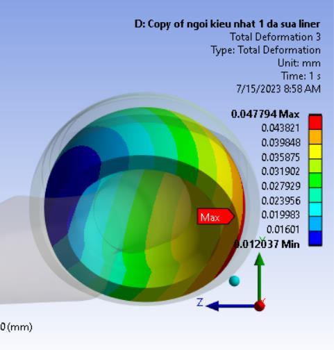
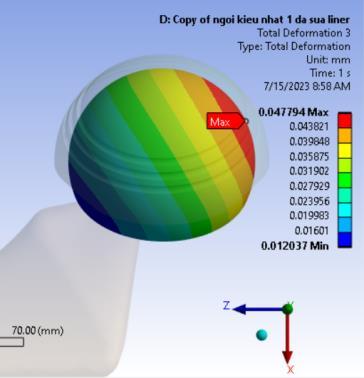
Figure -8: Thetotaldisplacementdistributiononthe LinerinBowingwhilesittingonlegsfullyflexedatthe kneeposition,Material1
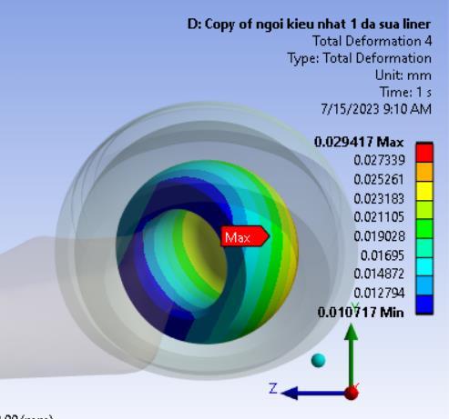
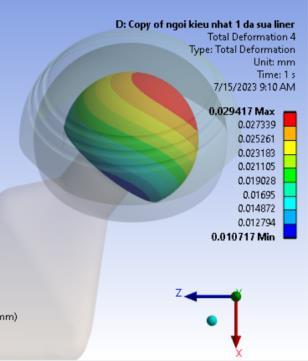
Figure -9: Thetotaldisplacementdistributiononthe HeadinBowingwhilesittingonlegsfullyflexedatthe kneeposition,Material1
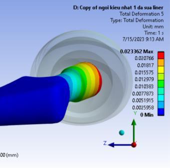
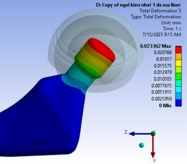
Figure -10: Thetotaldisplacementdistributiononthe SteminBowingwhilesittingonlegsfullyflexedatthe kneeposition,Material1
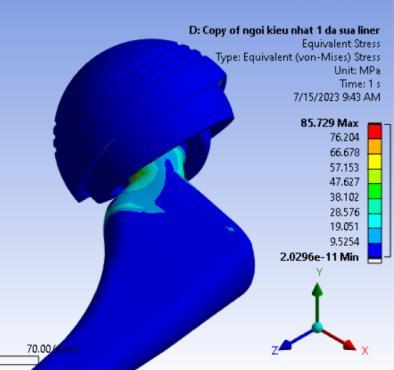

Figure -11: TheequivalentstressdistributionontheAHJ inBowingwhilesittingonlegsfullyflexedattheknee position,Material1
International Research Journal of Engineering and Technology (IRJET) e-ISSN: 2395-0056
Volume: 11 Issue: 10 | Oct 2024 www.irjet.net p-ISSN: 2395-0072
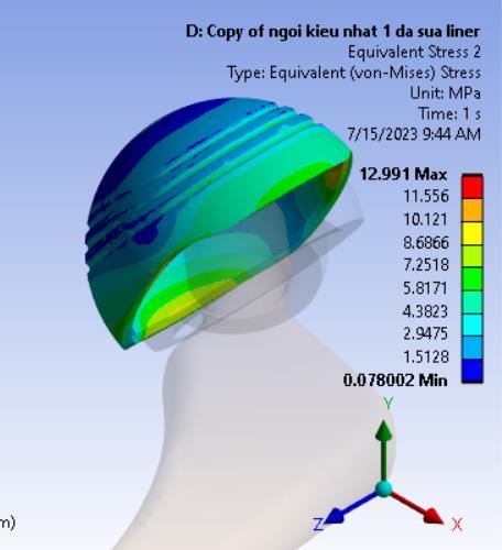
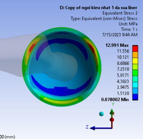
Figure -12: TheequivalentstressdistributionontheCup inBowingwhilesittingonlegsfullyflexedattheknee position,Material1
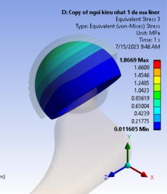
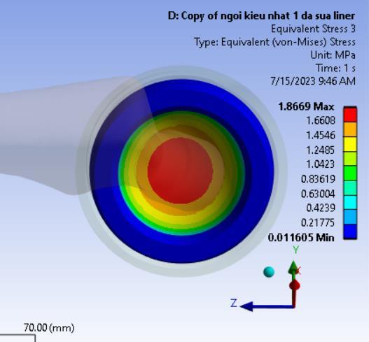
Figure -13: TheequivalentstressdistributionontheLiner inBowingwhilesittingonlegsfullyflexedattheknee position,Material1
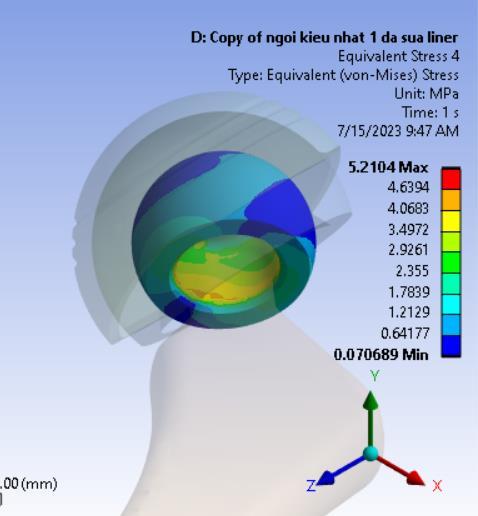
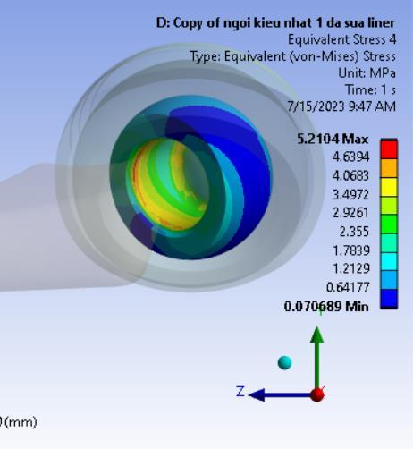
Figure 14: TheequivalentstressdistributionontheHead inBowingwhilesittingonlegsfullyflexedattheknee position,Material1
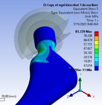
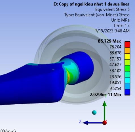
Figure -15: TheequivalentstressdistributionontheStem inBowingwhilesittingonlegsfullyflexedattheknee position,Material1
InTable10,itisobservedthatthehighestcontactpressure occursattheHeadandStem,followedbythecontactarea between the Liner and Head. The Bowing and squatting positionsexhibitthehighestcontactpressurebetweenthe HeadandStem(Figure16).AccordingtotheresultsinTable 10,slidingdistancesprimarilyoccuratthecontactbetween the Liner and Head. The greatest sliding distances are observed during normal walking, squatting, sitting down, andsittingupshowninFigure17.Theslidingdistancewill impactthewearoftheLinerandHeadcomponentsduring use, as the Liner material has a lower hardness than the Head material, resulting in wear primarily on the Liner (madeofHDPEmaterial),whichissafeforthehumanbody. AccordingtothediagramsinFigures16and17,thelargest sliding distance occurs between the Liner and Head parts andisnegligibleattheHeadandStemconnection.Therefore, eventhough thecontactpressureattheHeadandStem is large,wearwillmainlyoccurattheLinerandHead.
Table -10: Themaxcontactpressureandslidingdistance ofAHJinhumanactivities,Material1
Volume: 11 Issue: 10 | Oct 2024 www.irjet.net
Backward
Table -11: Themaxcontactpressureandslidingdistance ofAHJinhumanactivities,Material2
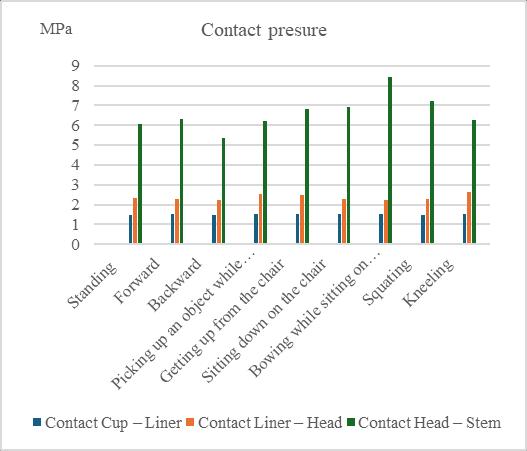
Figure -16: ThemaxcontactpressureintheAHJ, Material1
InMaterialGroup2,theslippingdistancebetweentheLiner and Head is approximately 5-6% higher compared to MaterialGroup1,whilethatbetweentheLinerandCupof Material Group 2 is reduced by about 10% compared to MaterialGroup1showninTable11.
International Research Journal of Engineering and Technology (IRJET) e-ISSN: 2395-0056
Volume: 11 Issue: 10 | Oct 2024 www.irjet.net p-ISSN: 2395-0072
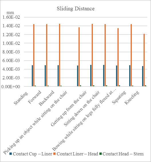
Figure -17: ThemaxslidingdistanceintheAHJ, Material1
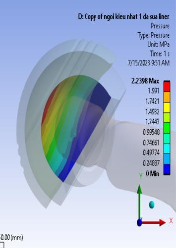
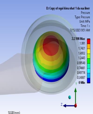
Figure -18: Thecontactpressuredistributionbetween Liner-CupinBowingwhilesittingonlegsfullyflexedat thekneeposition,Material1
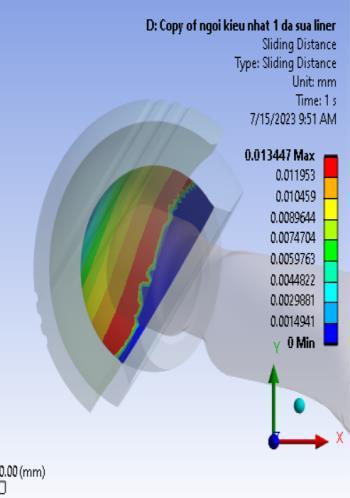
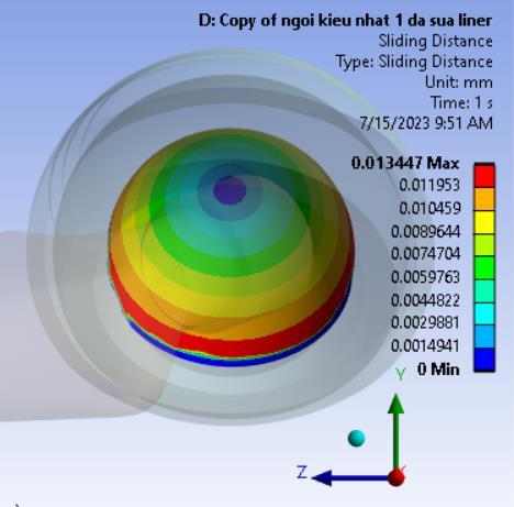
Figure -19:Theslidingdistancedistributionbetween Liner-CupinBowingwhilesittingonlegsfullyflexedat thekneeposition,Material1
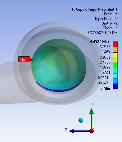
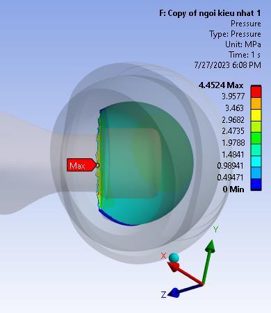
Figure -20: Thecontactpressuredistributionbetween Liner-headinBowingwhilesittingonlegsfullyflexedat thekneeposition,Material2
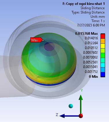
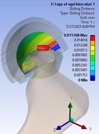
Figure -21: Theslidingdistancedistributionbetween Liner-headinBowingwhilesittingonlegsfullyflexedat thekneeposition,Material2
From the distribution of contact pressure and sliding distanceintheCupandlinerconnectionandthelinerand head connection in Fig 18 to Fig 21, contact pressure and slidingdistancehavegreatervalueintheouterrimonthe linerandheadcontact.
Thispaperpresentsthemechanicalbehaviorofthehipjoint in the daily activities of the surveyed patients, including stress distribution, strain distribution, and displacement distribution on the dual mobility artificial hip joint components. The daily activities of the patients include normal walking postures (standing, forward, backward), sittingonachair(pickingup,gettingup,gettingdown),and sitting on the ground without a chair (kneeling, bowing, squatting).Theseposturesaresuitableforthedailyactivities ofanAsianpatientingeneralandaVietnamesepatientin particular. From these results, it is possible to predict the patient's dangerous posture that should be avoided. The contactbehaviorbetweenthehipjointcomponentsinallthe aboveactivitiesofthepatientwasalsosurveyed,including parametersofcontactpressureandslidingdistance.These
International Research Journal of Engineering and Technology (IRJET) e-ISSN: 2395-0056
Volume: 11 Issue: 10 | Oct 2024 www.irjet.net p-ISSN: 2395-0072
parametersallowthepredictionofjointslippageandwear duringthepatient'slong-termactivities.
ThisresearchisfundedbyHanoiUniversityofScienceand Technology(HUST)underprojectnumberT2022-PC-033.
[1] Charles W Radcliffe “The Biomechanics of the Canadian-Type Hip Disarticulation Prosthesis” O&P LibraryArtificialLimbs,Vol4,no2,pp.29-38(1957).
[2] Derar H &Shahinpoor M “RecentPatentsandDesigns onHipReplacementProstheses” TheOpenBiomedical EngineeringJournal,no.9,pp.92–103(2015).
[3] EkoSaputraa,IwanBudiwanAnwara,J.Jamarib,Emile vanderHeidea “FiniteElementAnalysisofArtificialHip JointMovementduringHumanActivities” Proceeding Engineering,Vol68,pp.102-108(2013).
[4] FuziansyahBachtar XianChen ToshiakiHisada “Finite elementcontactanalysisofthehipjoint”,MedBioEng Comput,Vol44,pp.643–651(2006).
[5] Green D S & Schlegel J “A Polyaryletherketone BiomaterialforuseinMedical” Engineering Materials Science,Medicine(2006).
[6] K Saika “DesignAnalysisoftheBearingComponentof the Hip joint Prosthesis to Improve Distribution of Forces and Frictional Wear” Faculty of Health Engineering & Science, University of Southern Queensland(2016).
[7] Kurtz S M & Devine J N “Peek Biomaterials in Trauma Orthopedic andSpinalImplants” Biomaterials vol28(32)(2007).
[8] McLaurin C A “Hipdisarticulationprosthesis Report” No. 15, Prosthetic Services Centre, Department of VeteransAffairs,Toronto.Canada,(1954).
[9] YousufJamalMahboba,MohsinAbdullahAl-Shammari, “Improving of artificial hip joint design by studying multiple angles of articulation between femoral head andacetabularline” InternationalJournalofEnergyand Environment,Vol10,Issue4,pp.195-210(2019).
BIOGRAPHIES

Le Thi Bich Nam is a lecturer in the School of Mechanical EngineeringinHanoiUniversityof ScienceandTechnology.Hermain research field includes the finite elementmethodandthedynamic stiffness method in mechanical behavior of materials and structures.