
International Research Journal of Engineering and Technology (IRJET) e-ISSN: 2395-0056
Volume: 11 Issue: 10 | Oct 2024 www.irjet.net p-ISSN: 2395-0072

International Research Journal of Engineering and Technology (IRJET) e-ISSN: 2395-0056
Volume: 11 Issue: 10 | Oct 2024 www.irjet.net p-ISSN: 2395-0072
Kanifnath Baban Shelke1 , Dr. P. K. Kolase2 ,
1P.G. Student, Dept. of Civil Engineering, Pravara Rural Engineering College, Loni, Maharashtra State, India
2Professor, Dept. of Civil Engineering, Pravara Rural Engineering College, Loni, Maharashtra State, India
Abstract - There have been many various kinds of building failures during earthquake events in the past, thus it is crucial to comprehend building failure patterns and the causes of those failures in order to lower the building failure ratio and strengthen the building against future seismic occurrences. Seismic-induced pounding is one of the potential structural damages that most frequently results in significant building damage and has beenseeninanumberofpreviousearthquakes.Theuseof viscous dampers is being researched in the current study to prevent or lessen the impact of pounding between nearby buildings. Two nearby buildings, a 15-story building and an 11-story building in SAP2000, are evaluated to demonstrate the behavior and impact of viscous dampers. An examination of the linear time history of these two nearby buildings that experience ground motion during earthquakes has been conducted. For time history study, El Centro earthquake acceleration record(NS)is utilized.The building's behavior in relation tothepoundingeffectsiscomparedandinterpretedusing storeydriftandinter-storydriftvalues.
Key words: viscous dampers, pounding, reinforced concretebuildings
The simple definition of "pounding" is the collision of buildings that are constructed close to one another. The inadequate distance between the nearby buildings is the main cause of the seismic pounding. A multitude of other factors could also be involved, including the noncompliance with codal provisions, especially for lateral and torsional stiffness due to inadequate building configuration and structural framing system, the unexpectedseverityofthegroundmotion,andcumulative tilting caused by foundation movement. The majority of older structures that were built prior to the introduction and widespread use of earthquake-resistant design concepts exhibit this phenomena. Two kinds of pounding damageareoftenpossible.Thefirstisdamagethatoccurs locallyatthesiteofimpact,andthesecondisdamagethat occurs globally as a result of the collision's energy and momentumtransfer.Theforceofthecollisioncauseslocal damage, whilst the dynamic features of both buildings at the moment of the contact determine global damage. To maximize space use, buildings that are constructed without being divided all the way up to property lines
might sustain this kind of damage. If the floors of these structures are often built to the same height, pounding damageisusuallynotassevere;however,ifthisisnotthe case, there are two issues. Because the floors of nearby structures are at different altitudes, each structure's floor may operate as a ramp, hammering the other building's columns. When a building is higher than the other, the higher building has a significant stiffness discontinuity whilethelowerbuildingexperiencesanunexpectedlyhigh amountoflateralload.Evenifaminimumseismicspacing is specified by many modern codes, it is still insufficient. Globally, seismic rules and laws stipulate that, in order to prevent pounding, there must be a minimum space between neighboring structures that equals the relative displacement demand of the two potentially colliding structural systems. The previous seismic course did not provideclearrulestoavoidpoundingbecauseofeconomic factors, such as maximum consumption requirements, particularly in densely populated urban regions. Around the world, there are a lot of buildings that are either directly next to one another or already in contact and couldsustaincatastrophicharm.
The simplest and most efficient way to mitigate pounding and lessen damage caused by pounding is to provide enough separation; however, because of the high cost of land, this is not always possible. An alternative to providinga seismic separation gapistolessenthe impact of pounding by aligning floors in nearby buildings and reducinglateralmotiondrift.Toenhancetheperformance of structures lacking enough seismic separation between two buildings, several vibration reduction techniques can be taken into consideration as an additional strategy to lessen the impact of pounding during seismic excitation. Onemethodistoconnectthebuildingsnexttoeachother, which eliminates interactions by allowing forces to flow betweenthestructures.Forthisobjective,testshavebeen conducted on viscoelastic elements and stiff linkages. Adding more stiff beams to connect neighboring structures is another way to create a stiff link. Impacts may be partially absorbed and connections between nearby structures may also have certain energy dissipation characteristics. Structural conflicts between two neighboring structures can be controlled and eliminatedwiththeuseofjoiningelements.Inthecurrent study, the pounding effect is reduced and adjacent buildingsareconnectedusingfluidviscousdampers.
International Research Journal of Engineering and Technology (IRJET) e-ISSN: 2395-0056
Volume: 11 Issue: 10 | Oct 2024 www.irjet.net p-ISSN: 2395-0072
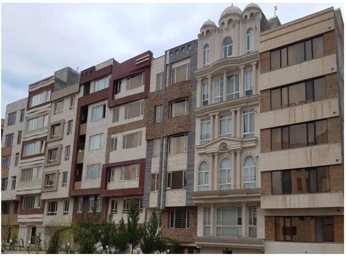
-1:AdjacentBuildingsinTehranwithdifferentfloor heights&withoutseparationgapbetweenthem
Basanagouda I. Patil, Bapugouda B. Biradar, and Rashmi Doddamani (2022) haspresentedintheirpaper “Mitigation of Seismic Pounding Observed in Adjacent Buildings with Fluid Viscous Damper.” The use of FVD to lessen the seismic pounding effect between nearby buildings.Themulti-storyneighboringbuildingsG+14and G+9 are modeled and examined using ETABS 2017. An investigation is conducted on nearby structures with varying heights (G+14 and G+9 floors) that are connected toFVDsimpactedbytheElCentroearthquake.Analysisof the non-linear temporal history is done. The comparison of nearby structures with and without FVDs is based on displacement and seismic spacing as important factors. When the displacement of structures with and without dampers is compared, it can be seen that the pounding impact is successfully managed when dampers are provided since they lessen building displacement. It was discovered that two storeys connected by a single fluid viscous damper (FVD) were very useful in preventing seismic pounding and very successful in minimizing seismicresponsesbetweenstructures.
Rajaram Chenna, Pradeep Kumar Ramancharla (July2018) has presented in their paper “Damage assessment due to pounding between adjacent structures with equal and unequal heights.” the investigation of pounding reactions and impact consequences on ground motion-exposed structures. A nonlinear time-history analysis with 20 mm intervals was carried out for nearby buildings that were experiencing ground motion from Northridge. Therefore, regardless of whether they are equivalent inheight or not, thepounding response ofstiff buildingsislargerthanthatofflexibleonesthroughoutthe dominantperiodoffrequencyofgroundmotion.Aflexible building will respond more forcefully than a stiff one if it vibrates at the non-dominant period or frequency of the ground motion. When two slabs collide on the same slab level, it results in a rigid body motion; however, when buildings are on separate levels, this interaction happens between the slab and the column and can be lethal.
Buildings with varying heights sustained greater damage than buildings with the same height, as this study's numericalresultsshowed.
B. Thamizhinian1, D Ghosh, H. Gupta, AK Mittal (2018) has presented in their paper “Seismic pounding effect on buildings and its control.” The impact of striking in highrisestructuresandmitigatingtheharmcausedbystriking usingappropriatedampers.Anonlinearanalysisofground motion was conducted with the Uttarkashi earthquake of 1991 in mind. Between the two buildings, there is a pounding effect that increases the stresses and shear forces on the components of the two buildings. The extra loads and displacements brought on by the pounding effect are managed by the employment of modeled dampers in the spaces between the buildings. Each case's acceleration and displacement time histories were evaluated, and the results were compared to determine how well the dampers controlled the seismic pounding between the nearby structures. Seismic pounding causes an increase in acceleration, storey displacement, and collision force that affects the nearby buildings. Buildings can be saved mostly by installing dampers between them and other neighboring structures to reduce the effects of pounding. A damper can be used to effectively lessen the displacementresponse.
E. Aydin, B. Ozturk, H. cetin and T. simsek (2017) has presented in their paper “Application of Viscous Dampers for Prevention of Pounding in Adjacent Reinforced Concrete Buildings.” The use of viscous dampers, which are passive dampers, to prevent or lessen the impact of pounding on nearby buildings is being researched. The behavior and impact of viscous dampers are examined in two nearby structures, each with 20 and 10 floors. Time history analyses are carried out for these two nearby buildingsthataresusceptibletogroundvibrationsduring earthquakes. The El Centro earthquake acceleration record (NS) is taken into consideration for time history analysis. The scenarios of viscous damper, uniform damper application, and no damper are compared for the model buildings. Building behavior in terms of pounding impacts is compared and interpreted using storey drift and inter-story drift values. It is concluded that story displacements and inter-story relative displacements are greatly reduced when viscous dampers are used for neighboring reinforced concrete buildings. Therefore, the pounding impact between adjacent structures can be lessened by installing a viscous damper. Based on the study's results, employing a single damper could be more advantageous and cost-effective than using viscous dampers that are evenly dispersed in terms of material, applicationtime,andcraftsmanship.
Elif Cagda Kandemir-Mazanoglu, Kemal Mazanoglu (2016) has presented in their paper “An optimization study for viscous dampers between adjacent buildings.” Theoptimalquantityandcapabilityofviscousdampersto
International Research Journal of Engineering and Technology (IRJET) e-ISSN: 2395-0056
Volume: 11 Issue: 10 | Oct 2024 www.irjet.net p-ISSN: 2395-0072
prevent structural pounding between two adjacent structuresduringseismicactivity.Thestructuresbelieved to be shear-type buildings are modeled using the lumped mass-stiffness approach. A nonlinear elastic spring approximation that mimics the impact forces from hammering is called the Hertz model. A parametric investigation is conducted by varying the number of stories, the stiffness of the buildings, the viscous damper capacity,andothercharacteristics.Thisstudydetailedthe optimization process to determine the position and capacity of the viscous damper between adjacent structures. Structural poundings can result from the various vibrational properties of nearby buildings, which can lead to dangerous damage. The auxiliary damping ratio and the change in pounding force are stated using a dimensionlessnaturalfrequencyscalethatwascreatedto compare situations involving structures with various structural features. The building's structural characteristics mostly determine the hammering force. Furthermore, it was determined that the impact force is notproportionaltothesupplementarydampingratioused forimpactprevention.
1.1 Provide minimum seismic gap between adjacent buildings
When there is not enough space between neighboring buildings to allow the relative motion during earthquake events, seismic pounding happens. In order to prevent pounding, neighboring buildings must have a minimum separationofatleasttherelativedisplacementdemandof the two possibly colliding structural systems, as specified byseismicrulesandregulations.
Minimum safe separation distance between adjacent structures according to the various codal provision are as showninTableNo1below
Table 1: Codalprovisionforminimumseismicgap calculation
3
INTERNATIONAL BUILDINGCODE
Δi1 = Peak displacement of building-1
Δi2 = Peak displacement of building–2
Si should not be greater than 0.04 times the height above the impact
δ M = √ (δ M12 +δ M22) (Adjacent Buildings located on the same property line) (Clause 1620.4.5 in IBC 2003 & Clause 1633.2.11)inUBC
(IBC)–2003 Where,
δM = Separation distance betweentwostructures
δ M1 and δ M2= Peak Displacement response of adjacentstructures1and2
4 NATIONAL BUILDING CODEPERUE.030-2003
The minimum separation distance will not be lower than 2/3 of the sum of the maximum displacements of the adjacent blocks nor less than S=3+0.004(h-500) (h and s in centimeters)
S>3cm(Clause3.8.2) h=Heightofstructure(incm)
δx=Cd.δmax/I as per (Clause 12.12.3)Where
5 ASCE/SEI–7-05
NO.
1 INDIA IS-1893:2016 CLAUSE7.11.3
Separation distance equal to R times the sum of the calculated storey displacements as the two buildings or two units of same building oscillate towards eachotherasperclause7.11.1.
R=Responsereductionfactor
2 FEDERAL EMERGENCY MANAGEMENT AGENCY–273-1997
Si=√(Δi12+Δi22)asperClause 2.11.10
Where
1.2
Cd = Total deflection amplificationfactor
δ max = Maximum elastic displacement that occurs anywhere in a floor from the application of design base shear tothestructure.
I = Importance factor for seismic loading
A mechanical device that dissipates the kinetic energy of seismic waves traveling through a building or other structure is known as a seismic damper. Innovative devices called earthquake dampers lessen the vibrations that buildings produce during an earthquake. Vibrations are caused by seismic waves penetrating through buildings.Thepurposeoftheseismicdamperistoreduce the dampening effect and enhance the structure's seismic performance.
International Research Journal of Engineering and Technology (IRJET) e-ISSN: 2395-0056
Volume: 11 Issue: 10 | Oct 2024 www.irjet.net p-ISSN: 2395-0072
Purpose of seismic dampers:
1. Protect the structure against earthquake by increasingthestrengthandlifespanofstructures.
2. Reduce the structural damage by decreasing the seismicforcewhichfurtherreducestructuraldeformation.
1. Linear ground motion analysis for adjacent R.C.C. Buildingswithdifferentgeometryandfloorheight inSAP2000.
2. To find minimum spacing requirements for safe separation distances between adjacent buildings toavoidPounding.
3. Control of additional stresses and displacements which are caused during Pounding by application ofa fluidviscous damperconnectedbetweentwo adjacentbuildings.
4. Evaluation of acceleration and displacement time historiesfor caseswithadequateseismic gapand FVD connected between adjacent buildings and compare them to obtain the effectiveness of the FVD in controlling the seismic pounding of buildings
5. Theamountofreductioninseismicgapsizewhile structuralpoundingcanstillbeprevented.
For adjacent R.C.C. buildings with unequal floor counts, different geometries, and varying floor to floor heights, non-linear ground motion analysis must be used to determine the minimum gap requirement, which provides the safe separation distance between the buildings for pounding avoidance with rigid floor diaphragms. A spring with the appropriate stiffness and a definedgapmakeupafluidviscousdamper,whichisused to mimic the gaps between the structures. The ground motion characteristics and metrics, including maximum lateraldisplacement,maximumstorydriftratio,maximum link displacement, time period, pounding force, etc., are compared in the time history study of the EL-Centro and Bhuj ground motion. The finite element analysis program SAP2000 is used in section 5.3 to replicate the structural parametersofbothR.C.C.buildings.Todevelop3Dmodels, analyses,anddesigns,thisisutilized.Thesoftwarecando nonlinear dynamic analyses, eigen values, and nonlinear staticpushoverinadditiontoacceptingstaticloads(forces ordisplacements)anddynamicactions(accelerations).
Following cases has been considered for analysis purpose:
i. Both buildings having floor to floor height 3.2m for EL Centro earthquake time history data withoutFVD.
ii. Both buildings having floor to floor height 3.2m for EL Centro earthquake time history data with FVD.
iii. Both buildings having floor to floor height 3.2m for Bhuj earthquake time history data without FVD.
iv. Both buildings having floor to floor height 3.2m for Bhuj earthquake time history data without FVD.
v.
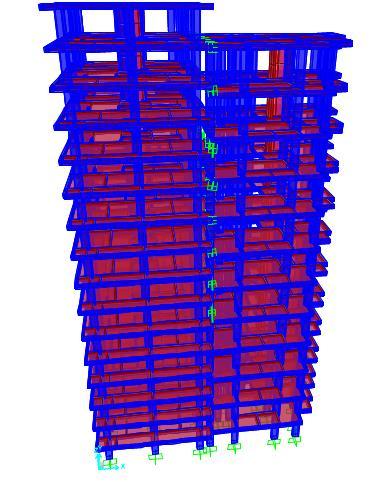
G+15 building with 3.2m floor to floor height & G+11buildingswith3.5mfloortofloorheightfor EL Centro earthquake time history data without FVD.
vi. G+15 building with 3.2m floor to floor height & G+11buildingswith3.5mfloortofloorheightfor ELCentroearthquaketimehistorydatawithFVD.
vii.
viii.
ix.
G+15 building with 3.2m floor to floor height & G+11buildingswith3.5mfloortofloorheightfor BhujearthquaketimehistorydatawithoutFVD.
G+15 building with 3.2m floor to floor height & G+11buildingswith3.5mfloortofloorheightfor BhujearthquaketimehistorydatawithFVD.
G+15 building with 3.2m floor to floor height & G+11 buildings with 4m floor to floor height for EL Centro earthquake time history data without FVD
x.
xi.
xii.
xiii.
G+15 building with 3.2m floor to floor height & G+11 buildings with 4m floor to floor height for ELCentroearthquaketimehistorydatawithFVD.
G+15 building with 3.2m floor to floor height & G+11 buildings with 4m floor to floor height for BhujearthquaketimehistorydatawithoutFVD.
G+15 building with 3.2m floor to floor height & G+11 buildings with 4m floor to floor height for BhujearthquaketimehistorydatawithFVD.
G+15 building with 3.2m floor to floor height & G+11buildingswith4.5mfloortofloorheightfor EL Centro earthquake time history data without FVD.
xiv.
xv.
G+15 building with 3.2m floor to floor height & G+11buildingswith4.5mfloortofloorheightfor ELCentroearthquaketimehistorydatawithFVD.
G+15 building with 3.2m floor to floor height & G+11buildingswith4.5mfloortofloorheightfor BhujearthquaketimehistorydatawithoutFVD.
International Research Journal of Engineering and Technology (IRJET) e-ISSN: 2395-0056
Volume: 11 Issue: 10 | Oct 2024 www.irjet.net p-ISSN: 2395-0072
xvi. G+15 building with 3.2m floor to floor height & G+11buildingswith4.5mfloortofloorheightfor BhujearthquaketimehistorydatawithFVD.
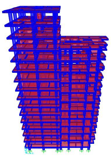
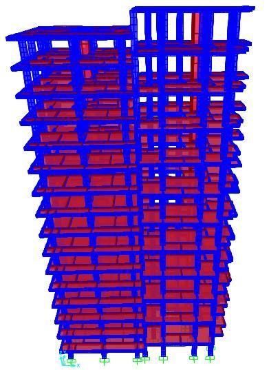
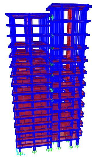
The models that have been chosen for the study aresymmetric(G+15)storeybuildingsandunsymmetrical (G+11) storey buildings in order to observe the pounding impact between nearby structures. There are different sizes of seismic gaps between these buildings. Both dynamic loading and gravity apply to these. "Frame elements" include beams and column members. Slabs are defined as area elements that are modeled as rigid diaphragms and possess the characteristics of membrane elements. The columns have been constrained and the interaction between the soil and structure has not been taken into Table No. displays the structural parameters needed for modeling and analyzing various structural instances. At the base, all six degrees of freedom are -5.1 below. Grade of concrete taken as M30 for column, beam andslab.Gradeofsteel-Fe500.
Structural parameters for modelling & analysisofdifferentstructuralcasesareasshownin TableNo:-2below:
Table 2 -DetailsofStructuralParameters
1.(Left Building) G+15
2. (Right Building) G+11
3.5m, 4.0m, 4.5m
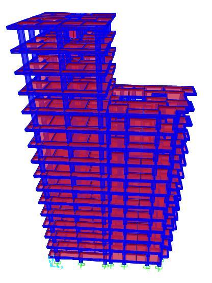
3:
ofG+15buildingwith3.2mfloortofloor height&G+11buildingswith3.2mfloortofloorheight withoutFVD
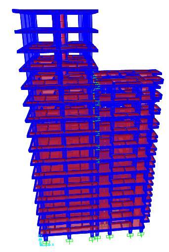
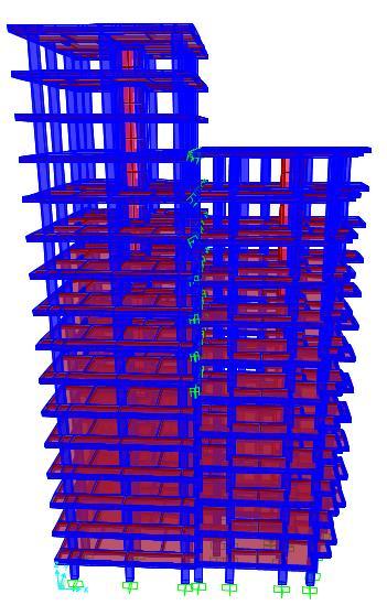
4:
ofG+15buildingwith3.2mfloortofloor height&G+11buildingswith3.2mfloortofloorheight withFVD
International Research Journal of Engineering and Technology (IRJET) e-ISSN: 2395-0056
Volume: 11 Issue: 10 | Oct 2024 www.irjet.net p-ISSN: 2395-0072
International Research Journal of Engineering and Technology (IRJET) e-ISSN: 2395-0056
Volume: 11 Issue: 10 | Oct 2024 www.irjet.net p-ISSN: 2395-0072
FVD250hasadampingforceof250kN,&Weightof41kg. DampingForce=Dampingconstant(C)xVelocity^αasper TaylordevicesincGeneralguidelinesforEngineers
Where α is the damping exponent which lies in the range of0.3to0.5forseismicapplicationsinbuildings.
To calculate Damping Constant (C) for this value of α considered is 0.3 and velocity=0.508 m/s is considered. ForFVD250,wegetvalueofC=299.9kN.sec/m
ForFVD250hasmodelnumber17120
ForFVD250wegetStiffness=625Kips/in=109455kN/m
3.
The analysis to be taken into consideration is the linear time history analysis for the ground motion of EL Centro andtheseismicmotionofBhuj.Thefindingsarederivedin terms of variance in the seismic gap needed to avoid ponding. Impact force is determined by the following factors: story drift ratio, storey displacement caused by theseismic gap,andlinkstiffnessanddamping.SAP2000 is used to calculate the structure's time period and link deformation,inadditiontothecode-providedcalculations.
SAP2000 software was used to analyze all models for earthquake data from Bhuj and EL Centro, both with and withoutfluidviscousdampersconnectedtothestructures. Various parameters have been compared regarding links, including base shear, maximum story displacement, maximum storey drift ratios, minimum seismic gap needed, maximum link deflection, time period, and maximum impact force. The findings are displayed both graphicallyandintabularform.
International Research Journal of Engineering and Technology (IRJET) e-ISSN: 2395-0056
Volume: 11 Issue: 10 | Oct 2024 www.irjet.net p-ISSN: 2395-0072
Maximum Lateral Displacement in mm
Maximum Lateral Displacement in mm
Chart-2: Variation of Maximum Lateral Displacement in mm for casesitoiv
Maximum Lateral Displacement in mm
Chart-3:VariationofMaximumLateralDisplacementinmmfor casesvtoviii
Maximum Lateral Displacement in mm
G+11
Chart-5:VariationofMaximumLateralDisplacementinmmfor casesxiiitoxv
Maximum storey drift ratio
G+11
Chart-4:VariationofMaximumLateralDisplacementinmmfor casesixtoxii
Chart-6:VariationofMaximumStoreyDriftRatioforcasesitoiv
Maximum storey drift ratio
Chart-7:VariationofMaximumStoreyDriftRatioforcasesvto vii
International Research Journal of Engineering and Technology (IRJET) e-ISSN: 2395-0056
Volume: 11 Issue: 10 | Oct 2024 www.irjet.net p-ISSN: 2395-0072
:VariationofMaximumStoreyDriftRatioforcasesixto xii
Chart-11:VariationofMaximumTimeperiodforcasesvtoviii
Chart-9:VariationofMaximumStoreyDriftRatioforcasesxiiito xvi
Chart-12:VariationofMaximumTimeperiodforcasesixtoxii
Chart-10:VariationofMaximum
VariationofMaximumTimeperiodforcasesxiiitoxvi
International Research Journal of Engineering and Technology (IRJET) e-ISSN: 2395-0056
Volume: 11 Issue: 10 | Oct 2024 www.irjet.net p-ISSN: 2395-0072
Table 2 -Valuesofmaximumseismicgapfordifferent cases
CaseNo. AsPerIS1893:2016 AsPerFEMA-273-1997
i 281mm
iii
v 588.975mm
vii 640.5mm
ix 660.65mm
xi 630.45mm
xiii 720mm 103.45mm
xv 715mm 102mm
The height of the G+11 structure increased from 3.2 meters to 4.5 meters, while base shear only increased by 3-4%. Since base shear is dependent on seismic weight and seismic characteristics such as soil type and seismic zones, this slight increase in base shear is caused by an increase in the structures' seismic weight while maintaining all other parameters constant. Using FVD has no effect on the basic shear value. When FVD is used, the modal time period is significantly reduced. The greatest reduction occurs when the floor-to-floor heights of the two structures are equal, or roughly 33%. The G+11 skyscraper experiences a minimum floor-to-floor height loss of 4.5 meters, or around 26%, as its height increases. When FVD is used, the maximum lateral displacement for G+15 buildings is significantly reduced roughly 30%. However,theusageofFVDincreasesthemaximumlateral displacement for the G+11 building since it dissipates energywithsomedeformation,whichraisesthemaximum lateral displacement in the G+11 building. Comparable outcomes were noted for the seismic data from Bhuj and ELCentro.
VariationofMaximumlinkdeflectionforcasesii,iv,vi, viii,x,
Story drift increases in the G+11 building as a result of energy dissipation at links, but it decreases dramaticallyintheG+15buildingwhenFVDisused.When FVD is linked, drift in the G+15 building is reduced by about 30%. For G+11 buildings, where a minimum floorto-floor height of 4.5 meters is required, this reduction in drift decreases as floor-to-floor height increases. Enhancing the seismic separation between two nearby buildings aids in preventing pounding. It is evident that theIScode'sminimumgapismorestringentthanFEMA's and ought to be adhered to in order to prevent the "pounding effect." The FVD link deformation is nearly the same for the earthquake data from Bhuj and EL Centro, anditisatitslowestwhenthefloor-to-floorheightsofthe two buildings are equal. However, the link deformation significantly increases as the floor-to-floor height of the G+11 building rises, reaching its maximum at 4.5 meters, or 40.141 millimeters, for the EL Centro earthquake data and 34.47 millimeters for the Bhuj earthquake data. This demonstrates that more hammering forces are produced when floor to floor heights differ. When comparing the impact forces from pounding action between the earthquakes in Bhuj and EL Centro, they are about 30–35% lower. Impact forces increase dramatically when G+11buildingfloortoceilingheightsrisefrom3.2meters to 4.5 meters, or 4642.52 kN for EL Centro and 3773.99 KNforearthquakedatafromBhuj.
VariationofMaximumimpactforceforcasesii,iv,vi, viii,x,xii,
Therefore, we may deduce that the pounding effect increases for both structures when the floor to ceiling height varies, with the G+11 building having the largest pounding effect at 4.5 meters. Energy dissipates, maximum lateral displacement balances out, and time
International Research Journal of Engineering and Technology (IRJET) e-ISSN: 2395-0056
Volume: 11 Issue: 10 | Oct 2024 www.irjet.net p-ISSN: 2395-0072
periodshortens whenFVD isused,all of whichlessenthe impactofearthquakepressuresonbothbuildings.
1. Chenna, R. and Ramancharla, P.K., 2018. Damage assessment due to pounding between adjacent structures with equal and unequal heights. JournalofCivilStructuralHealthMonitoring,8(4), pp.635-648.
2. Hameed, A., Saleem, M., Qazi, A.U., Saeed, S. and Bashir, M.A., 2012. MITIGATION OF SEISMIC POUNDING BETWEEN ADJACENT BUILDINGS. Pakistanjournalofscience,64(4).
3. Thamizhinian, B., Ghosh, D., Gupta, H. and Mittal, A.K., Seismic pounding effect on buildings and its control. 16th Symposium on Earthquake Engineering,IITRoorkee,IndiaPaperNo.335
4. Rajaram,C.andKumar,R.P.,2012.Comparisonof codal provisions on pounding between adjacent buildings. International Journal of Earth Sciences andEngineering,pp.72-82.
5. Patil, B.I., Biradar, B.B. and Doddamani, R., 2022. Mitigation of Seismic Pounding Observed in Adjacent Buildings with Fluid Viscous Damper. In Sustainability Trends and Challenges in Civil Engineering(pp.711-731).Springer,Singapore
6. Aydin, E.R.S.İ.N., Ozturk, B., Cetin, H. and Simsek, T., 2017. Application of viscous dampers for prevention of pounding in adjacent reinforced concrete buildings. In 16th World Conference on EarthquakeEngineering,Santiago,Chile.
7. Kandemir-Mazanoglu, E.C. and Mazanoglu, K., 2017. An optimization study for viscous dampers between adjacent buildings. Mechanical Systems andSignalProcessing,89,pp.88-96.
8. Uz, M.E. and Hadi, M.N., 2009, April. Dynamic analyses of adjacent buildings connected by fluid viscous dampers.InSeventhworldconferenceon earthquakeresistantengineeringstructuresERES VII. Limassol, Cyprus, Wessex Institute of, Technology(Vol.150,pp.139-50).