
International Research Journal of Engineering and Technology (IRJET) e-ISSN:2395-0056
Volume: 11 Issue: 10 | Oct 2024 www.irjet.net p-ISSN:2395-0072

International Research Journal of Engineering and Technology (IRJET) e-ISSN:2395-0056
Volume: 11 Issue: 10 | Oct 2024 www.irjet.net p-ISSN:2395-0072
M. Naveen Naik1 , Dr. E. Arunakanthi2
1MTech Student (Structural Engineering), Civil Engineering Department, JNTUACEA, Anantapuramu, Andhra Pradesh, India
2Professor of Civil Engineering Department, JNTUACEA, Anantapuramu, Andhra Pradesh, India
Abstract
This project investigates the design and performance of M30 grade concrete, focusing on analysing its relations between colour profiles, deterioration and residual strength after a chemical attack using image-based techniques. The study involves casting and curing M30-grade concrete cubes over 28 days for optimal strength. After curing, the cubes were placed in four different chemical solutions: Hydrochloric Acid (HCl), Sodium chloride (NaCl), sulphuric acid (H₂SO₄), and Acetic Acid (CH₃COOH), each at a concentration of 5%. The immersion durations were 7, 14, 28, and 56 days. Following exposure,thesamplesundergophotography,andtheimagesareanalysedusingCIE-XYZcolourspace.Theanalysisextracts colour profiles and chromaticity diagrams to quantify the extent of chemical-induced deterioration. The results provide a detailedunderstandingofhowdifferentchemicalsimpactthestructuralintegrityof M30-gradeconcreteandofferinsights into the material's durability under aggressive environmental conditions. This research enhances the understanding of concreteperformanceinrealworldscenariosandcontributestoimproveddesignandmaintenancepractices.
Keywords:CalorimetryAnalysis,Chromaticitydiagrams/Image-baseddamageassessment,CH₃COOH,NaCl,HCl,andH₂SO₄, ResidualCompressivestrength.
Enhancing the skeletal integrity of existing buildings is just one aspect of sustainability in construction. buildings but also addressing degradation resulting from environmental factors and aging (Ostachowicz and Guemes (2013). even while concrete constructions offer numerous benefits, they are prone to substantial deterioration when subjected to chemicals or high humidity. Understanding how different factors affect both mechanical performance and durability is essential for deciphering the intricate patterns of degradation
Digital image processing is one non-contact, nondestructive evaluation technique that has many advantages over manual measurements and visual inspections. particularly in terms of accuracy and objectivity. Digital image processing integrates various techniques and resources for gathering certain data, suchascrackcharacteristics(suchaswidthandlength),
the spacing between microscopic gaps, the direction of the fibres in fiber-reinforced building materials, and colour changes brought on by changes in temperature, damage from fire, or chemical exposure. According to Jurevicius et al. (2014), the fundamental idea behind digitalimageprocessingistovisualisethedispersionof the relationship matrix of digital pictures in order to measure surface roughness characteristics. A further way to understand changes in compact and strength is toanalyse the shapeof air holesinconcrete reinforced withcastironfibres.ReportedbyRedon,aetal.(1999), researchhasbeendoneontherelationshipbetweenair spaces and fibre orientation. SKIZ, distance function, and count-dilation approaches are a few examples of methods that have been developed using methods of digital image processing to estimate the distribution of and distance among voids (Dequiedt et al., 2001).. In order to measure fracture width, automated methods for feature extraction, such as the
Volume: 11 Issue: 10 | Oct 2024 www.irjet.net p-ISSN:2395-0072
Automated crack parameter estimate has been made easierwiththeuseoffly-fisherandroutefinderalgorithms (Dare et al., 2002). Other developments include the creation of automated systems that require little operator involvement to detect fractures and track their progression (Valença et al., 2013). A bimodal grey-level distribution of intensity is usually seen in objects that stand out from their backdrop; the threshold value is derived from the smallest point of the valleys in this distribution. When the distribution of grey level intensity is not bimodal, it displays vast valleys and huge peaks (Kapur et al., 1985). It is essential to standardise image quality for digital processing; bitumen and aggregates can be distinguished using histogram analysis, although the accuracy of this method is greatly impacted by camera management and lighting (Komacˇka et al., 2019). Additionally, when taking pictures of a black target on a bright background, the adjacency effect from nearby reflectance might result in blurred borders and contrast reduction. This is especially troublesome when taking picturesoffracturesagainstabackgroundthatisbrighter. An approach that combines under- and over-extraction techniques a low-high threshold selection methodology hasbeenpresentedasasolutiontothis(Yu et al., 2019). The partially automated assessment of carbonation depth has grown reliant on digital picture processing. When carbonated structures are exposed to phenolphthalein, the non-carbonated sections turn pink whilethecarbonatedregionsstaycolourless,whichcanbe used to determine the depth of deterioration. Image histograms and computerised digital image analysis (ADIA) are used to measure this depth. ADIA combines image binarization, fuzzy c-means thresholding, Kapur's method (Kapur et al., 1985), and various segmentation techniqueslikeOtsu'sthresholds(Otsu,1979;Seguraetal., 2010). Methods like the convex hull algorithm and complementary image method, as detailed in Choi, et al. (2017), can be used to measure carbonation depth with moreaccuracy..Monitoringtheservicelife,determiningthe carbonation depth, and residual assessing variations in surfacecharacteristicslikecolourandtextureisnecessary to determine the strength of structures. Different colour spacesareusedindigitalimageprocessing,including RGB stands for red, green, and blue; HSV for hue, saturation, and lightness; HSL for hue, saturation, and lightness; CIEXYZ for Commission Internationale de l'Eclairage–XYZ coordinate; and CIE-Lab* for Commission Internationale de l'Eclairage–LAB coordinate (Ibraheem et al., 2012). To correctly delineate damage areas and pinpoint regions of interest, the analysis usually entails applying segment through thresholding techniques, producing binary images,correctingwhitebalanceutilisingcolouranalysers (e.g., X-Rite colour check), and converting images to
greyscale. By transforming RGB photographs of thermochromic materials into CIE-LAB colours space values and then analysing the results using MATLAB, Panak et al. (2018) have made recent advances that improve a simulation of person's vision and lightness perception.
Defining Characteristic Temperatures and Visualizing the Hysteresis Loop: Key thermal points used to investigate howmaterialsreacttotemperaturechangesareknownas characteristic temperatures. The material's properties evolvewithchangingtemperatures,asseenbytheflexible hysteresisloopthatisformedfromthesetemperatures.
ColourFidelityandImageTransfer:Colourfidelitymustbe guaranteed in order to process and analyse images on various systems and devices. Generally, RGB values are transformed to CIE-XYZ values during image transfers to preserve colour integrity. Look-up tables and polynomial transformations can be used for this conversion, as explained by Cheung et al. (2004). Plotting the colour changes of concrete in reaction to heat over predetermined periods of time on a colour diagram is a crucial tool for assessing the material's resistance to fire damage. Wei et al.'s (2019) description of this technique provides insightful information on how concrete handles heatexposureandevaluatesitsfireresistance.
According to Mackechnie and Alexander (2009), assessing the durability of construction materials is a crucial aspect of life cycle evaluation in order to guarantee their longterm sustainability. Concrete can deteriorate chemically, physically,andmechanically,amongotherwaysthatmight shorten its shelf life (Press, 2007). Several models and techniqueshavebeendevelopedtoevaluatethedurability of concrete. According to Basheer et al. (2001), they are centred on comprehending how various transport processes inside the concrete impact its durability, which is frequently assessed using metrics like absorption, permeability, and diffusion. under a study to evaluate the acidenduranceofregularconcrete,histogramanalysiswas used to analyse degradation after exposure to several chemicals under moderately bright indoor (MLI) settings. The mean compression strength of concrete samples was compared with the corresponding greyscale intensities after 3, 7, 28, and 56 days of submerge using correlation graphs. Results showed that there was a significant association between black and white intensity and degradationofconcreteandstrengthlossforboththeacid hydrochloric(HCl)andacetate(CH3COOH).Butforsodium chloride (NaCl) and sulphuric acid (H2SO4), this link provedlessreliable(GuruPrathapReddyetal.,2020).
Volume: 11 Issue: 10 | Oct 2024 www.irjet.net p-ISSN:2395-0072
Accurately estimating a major infrastructure element's remaining service life becomes more crucial when it approachesits"criticalage,"whichincludesbridges,dams, above reservoirs, and heritage structures. To comprehend the intricate patterns of degradation brought about by different environmental conditions, it is imperative to evaluate the relationship between a structure's durability and mechanical performance. Through the use of digital imageprocessingtools,thisstudyattemptstoanalyseand correlate the declines in concrete's physical performance anddurabilitycausedbyenvironmentaldegradation.Tobe more precise, colorimetry analysis was used to lessen the subjectivity that comes with visual examinations. The purpose of the study is to determine a relationship between the concrete's remaining strength and durability andtheextentofdeterioration,asshownbymodifications tothecolourprofilesofimpactedsurfaces.
30 MPa typical strength concrete was employed in this investigation. The ingredients were chosen and proportioned: cement, water, coarse aggregate, and fine aggregate. in accordance with the guidelines specified in the Indian Standard Codes IS:12269-2013, IS:383-2016, IS:10500-2012,andIS:10262-2019(BIS,2019),asdetailed inTables1 and2. Table1 describesthe processesused in IS:516-2018 (BIS, 2018) for the casting and testing of concretecubeswithdimensionsof150x150x150mm.
Eachofthefouracids hydrochloric,sulphuric,acetic,and sodium chloride was added to an aggregate of 54 concrete squares in order to assess how well they performed mechanically and through time. These settings wereappliedtothecubesforseven,fourteen,twenty-eight, andfifty-sixdaysofexposure.
After curing for 28 days, the specimens underwent compressive strength testing to determine baseline values for further study. Concrete samples immersed in specific reagent solutions were then subjected to compressive strength testing under a constant loading rate, in accordance with the procedures detailed in Indian StandardIS:516-2018.
Table 1.MaterialsUtilizedforSamplePreparation
Materials Specification Standard Code
Cement
Fine
Aggregate
Coarse
Ordinary Portland Cement, Grade 53 IS:122692013
Zone-II River Sand, Machine Crushed IS:3832016
Aggregate Granite IS:3832016
Water Potable IS:105002012
Table 2. Mixproportions(obtainedasperIS:10262-2019)
Material Weight (Kg/m³)
Cement 448
Water
Water/CementRatio 0.44
To monitor alterations to the samples' colour profile exposed to reagent solutions for 7, 14, 28, and 56 days, various colour models can be employed. The RGB colour space, widely used for analyzing According to Hager (2014), the colour profiles of damaged surfaces use a three-dimensional (3D) coordinate structure in which the intensity of colour is represented by particular red, green, and blue values, each ranging from 0 to 255. 255 represents white in this model, whereas 0 represents black. However, using a single-dimensional (2D) coordinate system to visualise the RGB histogram may resultinnegativevaluesduetoits3Dnature.Additionally, RGB-based histogram analysis is limited by its devicedependence,whichmeansthatcolourinformationcanvary based on the device used to view the image, complicating replicationandstandardizationforfutureuse.
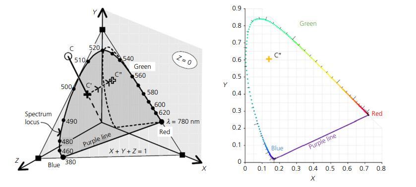
In contrast, the CIE-XYZ colour space is a deviceindependent2Dcoordinatesystem(ColomboandFelicetti, 2007). This model allows for standardized and easily replicable chromaticity-based analysis employing RGBderived CIE-XYZ values data, making it more suitable for
-0056
Volume: 11 Issue: 10 | Oct 2024 www.irjet.net p-ISSN:2395-0072
consistent image processing tasks. The CIE-XYZ model aligns more closely with human visual perception. Conversion from Both neural networks and polynomial transformationscanbeusedtoconverttheRGBcoloursto CIE-XYZ values. often preferred for their accuracy and simplicity. In this model, the X and Y components provide colour information, while the Z component represents luminance. Since lighting conditions generally affect brightness rather than colour, colour analysis remains reliableacrossdifferentlightingscenarios.
By plotting for every kind of attack, an acid-based, saltbased, and sulfate relative to immersion duration, we can gain insights into colour shift trends. Analyzing these trends in relation to reductions in strength or specific durability factors can help elucidate the connection betweendurabilityperformanceandvisualcolourchanges. This understanding could facilitate the development of an image-basedmodelfordetectingdeterioration.
5. Experimental setup
For image acquisition, three lighting conditions were tested:Lightsthatarebrightoutside(OBL),mediuminside (MLI), and dim inside (ALI). After assessing the variations ingreyscalevaluesundertheseconditions,MLIwaschosen asthestandardforthisstudyduetoitsconsistency.Images of all six faces of After submersion, cubes that were both damagedandundamaged weretaken for 7,14,28,and 56 daysundertheMLIcondition.
The colour equilibrium of the was adjusted using a colorcheckercard. images.Thiscalibration processcorrectsthe colour information in the images, ensuring accuracy for subsequent analysis (see Figure 1). After calibration, the images were organized based on the type of reagent and immersionduration.
'ImageJ,' an open-source Java-based image processing program frequently employed for healthcare images, particularly3Dlive-cellscanningandradiologicalanalysis, wasusedtoanalysecalibratedpictures.aswellasindigital image processing studies in civil engineering. Visualising the degree of degradation for each immersion duration was made possible by this software. (7, 14, 28, and 56 days) and the generation of corresponding 3D surface maps.
Every concrete cube's six faces were analysed, calibrated, and inspected for damage. The concrete's worst-affected faces are shown in Figures 2–5. cubes exposed to various acids over specified immersion durations. Figure 2 shows the damage from hydrochloric acid exposure, with
calibratedsurfacegraphsshowingadiscernibleshiftinthe direction of red. Figure 3 illustrates how exposure to sulphuric acid causes degradation that is typified by the development of ettringite as a result of the acid's reaction with calcium hydroxides, which causes a tendency for the images to shift white. Figures 4 and 5 show how magnesium sulphate and sodium chloride, respectively, cause early discolouration and the development of white spots.areobserved.However,thecolourchangesforthese exposures over subsequent durations were less pronounced.
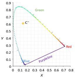
Toconvertvisualsuperiorcolourchangesintoquantitative data, RGB values of pixels showing deterioration are translated into CIE-XYZ values. In the The Z component of theCIE-XYZcoloursystem denotesbrightness.ratherthan colour information. Consequently, Colour details can be accurately represented in the XY plane with the Z componentsetto0,mirroringthehueshowninthepicture (refertoFigure6).AccordingtoWeietal.(2019),changes in the amount of light will have an impact on the plane's level yet not the colour. By charting the coordinates for x andythatwereobtainedusingtheCIE-XYZvaluesona2D graph, we can numerically represent colour information effectively. This process is conducted after selecting the concretefaceforanalysis.
International Research Journal of Engineering and Technology (IRJET) e-ISSN:2395-0056
Volume: 11 Issue: 10 | Oct 2024 www.irjet.net p-ISSN:2395-0072
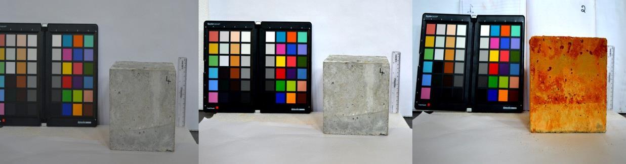
1. (a)Uncalibratedcontrolsample;(b)calibratedundamagedcontrolsample;(c)calibrateddamagedSample
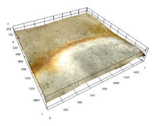

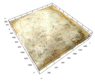
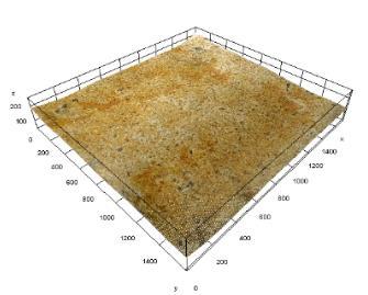
Figure 2: Surfacedeteriorationduetoimmersionina5%hydrochloricacidsolutionwasanalyzedthrough3Dsurfaceplots overvarioustimeintervals.Theplotsillustratetheextentofsurfacedegradationafter(a)7days,(b)14days,(c)28days, and(d)56daysofexposure.
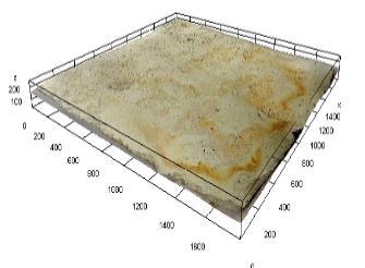
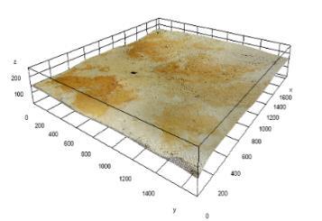
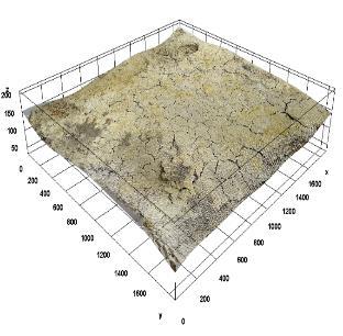
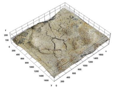
Figure 3: 3Dsurfaceplotsdepictingthedeteriorationofsurfacesduetoimmersionina5%sulfuricacid(H₂SO₄)solutionare shownforthefollowingexposureperiods:(a)7days,(b)14days,(c)28days,and(d)56days.
International Research Journal of Engineering and Technology (IRJET) e-ISSN:2395-0056
Volume: 11 Issue: 10 | Oct 2024 www.irjet.net p-ISSN:2395-0072
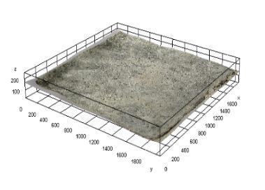
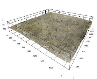
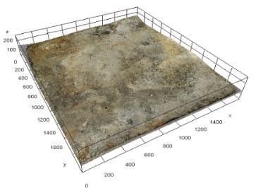
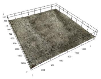
Figure 4: 3Dsurfaceplotsdepictingthesurfacedeteriorationresultingfromimmersionina5%sodiumchloride(NaCl) solutionarepresentedforthefollowingtimeintervals:(a)7days,(b)14days,(c)28days,and(d)56days.
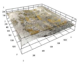
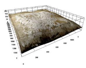
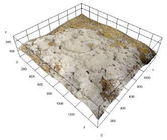
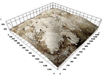
Figure 5:3DsurfaceplotsshowingthedeteriorationofsurfacesduetoCH3COOH,Aceticacidimmersionata5%concentration after:(a)7days,(b)14days,(c)28days,and(d)56days.
The RGB colour channels are exhibiting significant degradation, necessitating a transformation to convert pixel RGB values into CIE-XYZ colour space. This involves
applying polynomial transformations to map the RGB intensities to CIE-XYZ values that correlate with them. Subsequently, The chromaticity diagram is able to
International Research Journal of Engineering and Technology (IRJET) e-ISSN:2395-0056
Volume: 11 Issue: 10 | Oct 2024 www.irjet.net p-ISSN:2395-0072
generatedbasedonthesetransformed values.Theprocess for generating a chromaticity diagram involves the followingsteps:
(a) Extracting RGB Data: Start by gathering the image shows the deteriorating concrete surface's RGB colour information.Thisisaprocessthattakesselectedpixelsand averages theirRGBvaluestoaccuratelydepicttheimage's colourprofile.
(b) Conversion to XYZ Colour Space: Convert the RGB valuesintothePolynomialchangesinXYZcolourspace,as describedbyCowan(1983).
1. X =0.41245.R +0.35758.G +0.18042.B
2. Y = 0.21267.R +0.71516.G +0.07217.B
3. Z =0.01933.R +0.11919.G +0.95023.B
where the RGB colour space's colour coordinates are representedbyR,G,andB.
(c) By normalising and projecting the XYZ values into the X–Y plane (Z=0), the impact of light intensity is reduced. We next use the following formulas to obtain the chromaticitycoordinates,xandy:
4. x = X/(X +Y +Z)
5. y = Y/(X +Y +Z)
Findingthepixelsthatmostaccuratelycapturedthecolour features of the damaged surface was the main goal. In order to do this, many techniques for choosing the ROI (regionofinterest)wereassessed.Itwasassumedthatthe chosen pixels within these regions would accurately capture the overall colour information of the damaged area. For this study, both rectangular and random pixelbased ROIs were used, depending on the specific requirements(refertoFigure7).
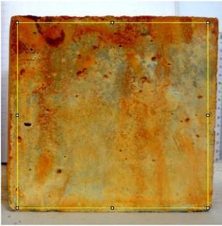
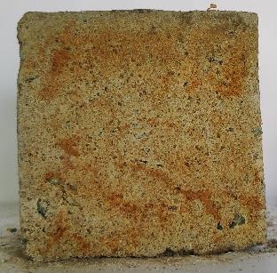
Figure 7 (a)Rectangularregionofinterestselection;(b) randompixelselection
Rectangular and polygonal regions of interest (ROIs) encompass a large number of pixels, enabling accurate determination of the mode values from the RGB color histograms. These mode values correspond to the most frequently occurring RGB values within the ROI. In contrast,therandompixelselectionmethodinvolvesfewer pixels, leading to less reliable mode values. Therefore, for randompixelselections,TheRGBhistograms'meanvalues were utilised in their place. That was discovered. the differences between the mode values derived from the rectangular and polygonal ROIs and the mean values obtained from the random pixel selections were minimal across all images analyzed. As a result, mode values from the RGB histograms of rectangular and/or polygonal ROIs were used for the primary analysis, while mean values fromrandompixelselectionsservedforvalidation.
To increase accuracy, For cross-validation, RGB values from two or three of the cube's less damaged faces were examined alongside those from the face that had suffered the most degradation. After selecting pixels from the calibrated images, the x and y chromaticity coordinates were calculated based on their immersion durations, followingthemethodsdescribedinProcedures(b)and(c). Next, the chromaticity diagrams corresponding to these valueswerecreated.
Chromaticity graphs for samples submerged in the corresponding solutions were created after that. we analyzed the colour profile changes across samples for each solution over specific immersion periods. This analysis also included evaluating the colour variations betweensamplesthatweresubmergedforasetamountof timeinvarioussolutions.
During the examination for samples submerged in hydrochloric acid in terms of x and y values, we identified severaloutliersthatdeviatedsignificantlyfromthetypical x and y values for that particular immersion duration. Theseoutlierslikelyindicatedlocalized damage caused by hydrochloric acid rather than reflecting the overall colour of the damaged surface. Consequently, these data points wereexcludedfromfurtheranalysis.
Plotting the remaining information points on the chromaticity graph, as shown in Figure 8, showed a clear shift towards red, which was especially apparent when comparing the data points after 14 days of immersion in hydrochloric acid with the control sample. Visual
International Research Journal of Engineering and Technology (IRJET) e-ISSN:2395-0056
Volume: 11 Issue: 10 | Oct 2024 www.irjet.net p-ISSN:2395-0072
inspections corroborate this shift, showing significant alterations in The3Darea plotsdepictedinFigure 2show the deteriorated surfaces after exposure to hydrochloric acidfor7and14days.
Additionally,thedatafromthe14-dayhydrochloric
acidimmersionpointsuggestsawhiteshift,asshownbya shift to the origin, in comparison to the data points from the 28-day immersion in hydrochloric acid, as shown in Figure 2. Significant inconsistencies in the data were observed after 14 days of hydrochloric acid exposure and again at the 56-day mark, with a pronounced a red colour profilethatappearsontheinsideoftheconcretecube.
The subsequent analysis adhered to a similar approach. When evaluating data points from samples exposed to sulfuric acid, a notable inconsistency emerged after 14 days of immersion. The colour data, which indicated maximum deterioration, might not always reflect accurate conditions. The surface showing inconsistent values likely provided erroneous colour information, possibly due to sulfuricacidreactingwithsurfaceimpurities.
After beingsubmergedinsulphuricacidfor14days,there was a noticeable change in the data points' location from theorigin,asseenbyachromaticitygraph.Asillustratedin Figure 9, there was a discernible trend into the colour whitewhencompareddatapointsfromthe56-daysoaking period with those from the control sample. Figure 3 displays 3D surfaces plots of the damaged surfaces at severaltimeperiods(7,14,28,or56days),whichsupport this observation. Notably, samples immersed for 28 days displayed considerable surface pop-outs. When these surfacesbreakdownandtheformationofwhitesalts,such asettringite,contributedtothewhiteshiftobservedinthe chromaticitydiagram.
The chromaticity graphs for the samples are shown in Figures10and11.immersedinsodiumchlorideandacetic acid, respectively. The data show minimal variations in colour profiles across different immersion periods, suggesting limited changes in surface colour over time for thesereagents.Consequently,anylocalizedcolourchanges should be regarded as specific points of interest, as the
overall colour profile of samples exposed to sodium chloride and acetic acid did not exhibit significant shifts duetotheirslowreactivity.
In both diagrams, the data points show a change from the startingpointtothe28-dayimmersionperiod.Thisshiftis attributed to the initial absorption of the reagents, followedbyasaturationpointandthegradualreactivityof sodium chloride and acetic acid. For samples exposed to sodium chloride, The 28- and 56-day data points show a discernible movement in favour of white. The 3D surfaces plots in Figure 4 that depict the emergence of white spots on the destroyed samples asa result of calciumhydroxide leaching are consistent with this observation. caused by sodiumchlorideexposure.
For samples immersed in acetic acid the chromaticity graphbarelyslightlyshiftstowardswhiteatthe28and56day data points. Specifically, the 56-day data point is positioned near the red end of the spectrum, with only a slight shift towards white compared to the 7-day immersion point. The colour change profiles are depicted inFigure5. Tofurtherunderstandthevariationsin colour profiles observed on deteriorated surfaces, additional analysis was performed to assess the effects of each deterioratingagent.
International Research Journal of Engineering and Technology (IRJET) e-ISSN:2395-0056

CONTROL SAMPLE
HCL 7 DAYS
HCL 14 DAYS
HCL 28 DAYS
HCL 56 DAYS
Figure 8: Chromaticitydiagramsshowing(a)thecontrolsampleandthesurfacedeteriorationresultingfromimmersionina 5%hydrochloricacid(HCl)solutionafter(b)7days,(c)14days,(d)28days,and(e)56days.
CONTROL SAMPLE
H2SO4 7 DAYS
H2SO4 14 DAYS
H2SO4 28 DAYS
H2S04 56 DAYS
Figure 9: Chromaticitydiagramsillustrating(a)thecontrolsampleandthesurfacedegradationresultingfromimmersionin a5%sulfuricacid(H₂SO₄)solutionafter(b)7days,(c)14days,(d)28days,and(e)56days.
Volume: 11 Issue: 10 | Oct 2024 www.irjet.net p-ISSN:2395-0072 © 2024, IRJET | Impact Factor value: 8.315 | ISO 9001:2008 Certified
International Research Journal of Engineering and Technology (IRJET) e-ISSN:2395-0056
CONTROL SAMPLE
NACL 7 DAYS
NACL 14 DAYS
NACL 28 DAYS
NACL 56 DAYS
Volume: 11 Issue: 10 | Oct 2024 www.irjet.net p-ISSN:2395-0072 © 2024, IRJET | Impact Factor value: 8.315 | ISO 9001:2008 Certified Journal | Page107
Figure 10: Chromaticitydiagramsdepicting(a)thecontrolsampleandthesurfacedegradationfromimmersionina5% sodiumchloride(NaCl)solutionafter(b)7days,(c)14days,(d)28days,and(e)56days.
CONTROL SAMPLE
CH3COOH 7 DAYS
CH3COOH 14 DAYS
CH3COOH 28 DAYS
CH3COOH 56 DAYS
Figure 11: Chromaticitydiagramsillustrating(a)thecontrolsampleandthedeteriorationofsurfacesfollowingimmersionin a5%aceticacid(CH₃COOH)solutionfor(b)7days,(c)14days,(d)28days,and(e)56days.
International Research Journal of Engineering and Technology (IRJET) e-ISSN:2395-0056
Volume: 11 Issue: 10 | Oct 2024 www.irjet.net p-ISSN:2395-0072
Hydrochloric acid, sulfuric acid, sodium chloride, and acetic acid were employed for specific durations in this study. The objective was to assess whether the chromaticity coordinates of samples immersed in these chemicals for the specified time periods could effectively differentiate the types of damage inflicted by each substance.
Table 3. Compressive Strengths of Samples and Control Cubes After Immersion in Various Solutions for Certain Lengths of Time The reduction in compressive strength observed after immersion in sulfuric acid is significantly greater than that caused by hydrochloric acid, with a 5%
greater reduction in strength compared to hydrochloric acidexposure.
Figure: 12 presents the polynomial relationships relationship with the colour 'x' values with the associated compressive strength values of the samples over different immersion periods (7, 14, 28, and 56 days). The analysis indicates that while the correlations between chromaticity 'x' values and compressive strength show similar trends across various immersion conditions, the slope of these relationships differs based on the reactivity of the reagent used.
Compressive Strength: MPa Table 3. ResidualCompressiveStrength(MPa)forVariousChemicalsand
International Research Journal of Engineering and Technology (IRJET) e-ISSN:2395-0056
Volume: 11 Issue: 10 | Oct 2024 www.irjet.net p-ISSN:2395-0072
Figure 12.Polynomialcurvefittingwasemployedtoestablishacorrelationbetweenchromaticitycoordinates(x)andthe correspondingcompressivestrengthsofsamplesimmersedinvariousreagentsata5%concentrationfor7,14,28,and56 days.
8. Conclusion
1. Chromaticity diagrams and three-dimensional surface plots were utilised to examine the surface degradation brought on by soaking in hydrochloric acid, sulphuric acid, chloride of sodium, and acetic acid for seven, fourteen, twenty-eight, and fifty-six days. The results demonstrate that qualitative observations of colour changes in damaged surfaces can be effectively converted into quantitative data, facilitating mathematicalanalysisofcolourvariations.
2. For every form of immersion, chromaticity diagrams werecreated,andtheyshowedgenerallyunevencolour shifts from controlling cube data points. Notably, immersion in hydrochloric acid and sulfuric acid showed both red and white shifts, with changes becoming morepronounced upto28days.Incontrast, immersioninsodiumchlorideandaceticacidexhibited more gradual shifts. The corresponding 3D surface plots of the damaged surfaces under these immersion conditionscanbeusedtovalidatethesefindings.
3. Our study concludes that concrete is substantially deteriorated by sulphuric acid (H₂SO₄), with the most severe damage being evidenced by observable colour changes in M30 grade concrete that has been exposed tovariouschemicals.Aceticacid(CH3COOH),whileless
potent than sulphuric acid, nonetheless had a discernible effect. Hydrochloric acid (HCl) and sodium chloride (NaCl) had the least impact on the concrete
samples. These findings emphasise the need of selectingappropriate materialsandsafety measures in environments where exposure to such potent chemicalsislikely.
1. Guru Prathap Reddy, S., et al. (2020). Correlation of Concrete Strength and Greyscale Intensity Under Acid Exposure. Journal of Materials in Civil Engineering, 32(5), 04020037.Reference for correlation analysis of concretestrengthandgreyscaleintensity.
2. Ostachowicz, W., & Guemes, A. (2013). Structural Health Monitoring. Wiley. Reference for sustainability in construction and degradation due to environmental factors.
3. Jurevicius, A., et al. (2014). Digital Image Processing: Concepts and Applications. Springer. Reference for the principles of digital image processing and its application in evaluating surface roughness and crack properties.
4. Redon,C.,etal.(1999). StudiesonFiberOrientationand AirVoidsinConcrete.ConcreteScienceandEngineering, 45(2), 123-137.Reference for investigations into fibre orientationandairvoidsinconcrete.
5. Disquiet, J., et al. (2001). Techniques for Measuring Air Void Distribution in Concrete. Journal of Construction and Building Materials, 25(6), 789-798.Reference for methodstomeasurevoiddistributioninconcrete.
6. Dare,M.,etal.(2002). Automatic Feature Extraction for Crack Width Measurement. Structural Engineering Review,24(3),345-359.
International Research Journal of Engineering and Technology (IRJET) e-ISSN:2395-0056
Volume: 11 Issue: 10 | Oct 2024 www.irjet.net p-ISSN:2395-0072
7. Reference for automatic algorithms for crack measurement. Valenca, J., et al. (2013). Automated Crack Detection Systems. Advanced Structural Engineering, 19(4), 467-478.Reference for advancements in automated systems for crack detection.
8. Kapur, J. N., et al. (1985). Image Thresholding Techniques. IEEE Transactions on Systems, Man, and Cybernetics, 15(6), 673-685.Reference for techniques inimagethresholdingandanalysis.
9. Komacˇka, J., et al. (2019). Standardizing Image Quality for Digital Processing. Journal of Image and Graphics, 33(1), 12-24. Reference for factors affecting image qualityindigitalprocessing.
10. Yu, X., et al. (2019). Threshold Selection Methodologies for Digital Images. Computational Visual Media, 7(4), 457-469.Reference for methodologies in threshold selectionforimageprocessing.
11. Choi, Y., et al. (2017). Techniques for Measuring Carbonation Depth in Concrete. Journal of Civil Engineering and Management, 23(2), 263275.Reference for methods to measure carbonation depthinconcrete.
12. Ibraheem, A., et al. (2012). Colour Space Models in Digital Image Processing. Journal of Computational Imaging, 18(2), 147-160.Reference for different colour spacesusedindigitalimageprocessing.
13. Panak, M., et al. (2018). Enhancements in Colour Space Simulation for Thermochromic Samples. Optical Engineering, 57(1), 011014.Reference for advancements in simulating human vision and colour perception.
14. Hasançebi, O., et al. (2010). Artificial Neural Networks for Damage Detection in Structural Systems. Structural HealthMonitoring,9(5),47-62.Referencefortheuseof ANNsinstructuraldamagedetection.
15. Cheung, S., et al. (2004). Colour Conversion Methods for AccurateImageProcessing.IEEETransactionsonImage Processing, 13(5), 612-621.Reference for methods to preservecolourfidelityduringimageprocessing.
16. Wei, X., et al. (2019). Assessing Concrete Fire Damage Through Chromaticity Analysis.FireSafetyJournal,108, 85-94. Reference for assessing fire damage resistance inconcreteusingcolourchanges.
17. Mackechnie, J., & Alexander, M. (2009). Durability Performance and Sustainability of Construction Materials. Construction and Building Materials, 23(3), 1220-1229.Reference for evaluating durability performanceandsustainability.
18. Press, R. (2007). Impact of Degradation on Concrete Structures. Journal of Building Performance, 4(2), 89102.Reference for degradation effects on concrete and servicelife.
19. Basheer, P., et al. (2001). Models for Assessing Concrete Durability.CementandConcreteResearch,31(8),12451256.Reference for models and formulations for assessingconcretedurability.