
International Research Journal of Engineering and Technology (IRJET) e-ISSN:2395-0056
Volume: 11 Issue: 10 | Oct 2024 www.irjet.net p-ISSN:2395-0072

International Research Journal of Engineering and Technology (IRJET) e-ISSN:2395-0056
Volume: 11 Issue: 10 | Oct 2024 www.irjet.net p-ISSN:2395-0072
Andriya narasimhulu1 , Prabhinder Singh Sahni2, Aditya Jain3, Japneet Singh4 , Aniket Burman5
1Professor, Mechanical Engineering, Netaji Subhas University of Technology 2,3,4,5 Students at Netaji Subhas University of Technology, Mechanical Department ***
Abstract -This research paper aims to develop a Magneto-Rheological Fluid Brake (MRB) model in conjunction with an Anti-Lock Braking System (ABS) that showcases better performance than Conventional Hydraulic Brakes (CHB). This proposed MRB system is then compared with the CHB model. The MRB system integrates mechanical and electronic components with MR fluid, enabling more efficient and reliable braking actuation. A quarter-vehicle model integrated with a sliding mode controller is utilized to maintain optimal traction between tires and road to avoid tire locking. However, during the implementation of the sliding mode controller, occurrence of chattering, a detrimental effect, is observed. To mitigate this issue, a saturation function is applied. Finally, a more effective eradication of chattering is achieved by developing a timevarying saturation boundary layer across the switching surface. The results demonstrate significant improvements in braking performance and offer valuable insights for futureadvancementsinautomotivebrakesystems
Key Words: Magneto-rheological, Anti-Lock Braking system,SlidingModeController,QuarterVehicleModel
Working: Conventional hydraulic brakes use an arrangement of brake pedal which is connected to a circuit(hydraulic). First brake pedal has to be pressed whichimpelsthefluidintothemastercylinderthatresults in pressure that pushes brake shoes against the wheels which causes braking torque to be generated because of friction[1].
Applications: CHB is commonly used in modern commercial vehicles. It is also used widely in conjunction with various other technologies like ABS, regenerative breaking,VehicleCruiseControletc.
Limitations: Although popular, the CHB systems do have several limitations which are discussed in the following lines. Brake fluid under unfavorable conditions are found tobeleaking,therebyleachingintosoil and water bodies, andhencebecomingdetrimentaltotheenvironment.They are bulky in size whose installation and maintenance is challenging. The pads used in brakes wear out over time
and need to be replaced regularly, which causes inconvenience and is expensive. These systems have a certain amountof delayintheir responsetime,whichcan affect the effectiveness and precision of braking actions. This delay can lead to longer stopping distances and reducedcontrolduringcriticalsituations[2].
1.2.1 MR fluids
MR fluid is a smart material whose rheological characteristics change under the influence of magnetic field.Thefluidisproducedbymixingmicron-sizedironor particles of carbonyl to carrier fluid such as oil or water andsilicon.Whenthefluidissubjectedtoamagneticfield, the state of the substance changes from a fluid to a viscoelastic solid. The particles of iron particles obtain a dipole moment under the influence of magnetic field to formlinearchainsparalleltothedirectionofthemagnetic field. Therefore MR fluid has a controllable yield strength that directly depends upon the magnitude of the applied magneticfield[3].
1.2.1 MR fluids
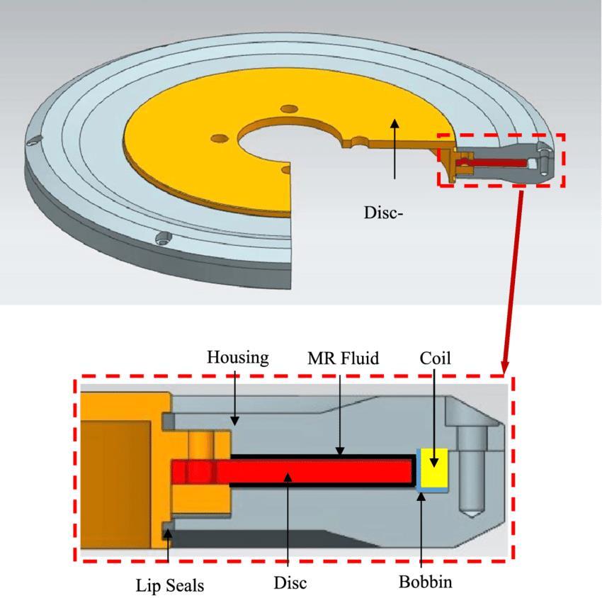
MRB is a friction-based braking system. In this braking system,themagneto-rheologicalfluidisfilledbetweenthe rotor and stator as shown in Figure 1. Since the fluid has controllablerheologicalpropertieswhichhelpstoproduce shearforcethusgenerating brakingtorque.Whencurrent flowsthroughthecoil,amagneticfieldisgeneratedwhich converts the magneto-rheological fluid in the gap into a solid-likesubstanceimmediately.Itisareversibleprocess, when the current flow through the coil stops, the applied magnetic field also stops which allows the MR fluid to returntoitsliquidstate[4].
TheMRBhasmanyadvantagesoverCHBsuchas:
● Better control and near instantaneous response time
● Since MRB doesn’t utilize the friction generated between the brake pads and rotor to slow down the car, thus significantly reducing the wear and tear between components. Hence longer service lifeandlessmaintenance
International Research Journal of Engineering and Technology (IRJET) e-ISSN:2395-0056
● MRB has better energy efficiency since it generateslessheatduringthebrakingoperation
● Easy integration with other electronic componentsofthevehicle
2. Methodology
The research aims to optimize the MR fluid brake model andconductacomparativeanalysiswiththeconventional hydraulicbrakemodel,therebyprovidinginsightsintothe potential advantages of MR fluid brakes in braking applications.
1. CHB Model construction: Model of CHB in conjunction with ABS is developed. The model utilizes vehicle dynamics and uses the Bang-Bang controller to maintainoptimalslip-ratio.
2. MRB Model and optimization: Model of MRB is developed using the quarter vehicle model which utilizestheslidingmodecontrollertokeepaconstant valueoftheslipratio.
3. Comparative Analysis: Using the MATLAB models of thetwobrakingsystems,Comparativeanalysiswillbe performedonthefollowingparameters:
3.1. Stoppingtime
3.2. Stoppingdistance
3.3. IntegralSquaredError(ISE)
3.4. IntegralTime-weightedAbsoluteError(ITAE)
Volume: 11 Issue: 10 | Oct 2024 www.irjet.net p-ISSN:2395-0072 © 2024, IRJET | Impact Factor value: 8.315 | ISO 9001:2008
3. Computational Modeling and Comparative Analysis of MRB and CHB
Table -1: Parameters of the Vehicle
Wheelradius, 0.326m

Wheelbase, 2.5m heightofthepointofcenter ofgravity, 0.5m

Wheelmass, 40Kg

Quartervehiclemass, 415Kg
3.1 Modeling of CHB and ABS
Table -2: Parameters pertaining to hydraulic brakes numberoffriction surfaces,n 2
DragCoefficient 0.539

ProjectedArea 2.04
Maxpressure 20x


DiscbrakeCoefficient offriction 0.34
The model is created utilizing an earlier study [6], following results are obtained:
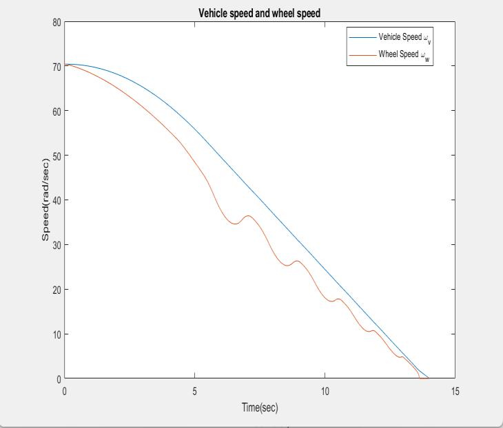
Chart -1:Vehiclespeedandwheelspeed
International Research Journal of Engineering and Technology (IRJET) e-ISSN:2395-0056
Volume: 11 Issue: 10 | Oct 2024 www.irjet.net p-ISSN:2395-0072
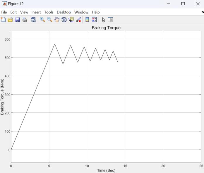
Chart -2:BrakingTorque
Vehicle and wheel speed:Chart-1showsthevariationin car speed and wheel speed over time during the braking event.IthighlightstheeffectoftheABScontrolsystemand the hydraulic brake in controlling the wheel speed and preventingwheellock-up.
Braking Torque: Chart - 2 illustrates the variation in braking torque applied by the hydraulic brake system during the braking event. It shows how the torque generated due to braking adjusts to keep a constant slip ratio of 0.2, ensuring effective braking while preventing wheellock.
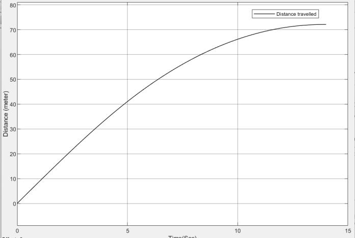
Chart -3:StoppingDistanceofthecar
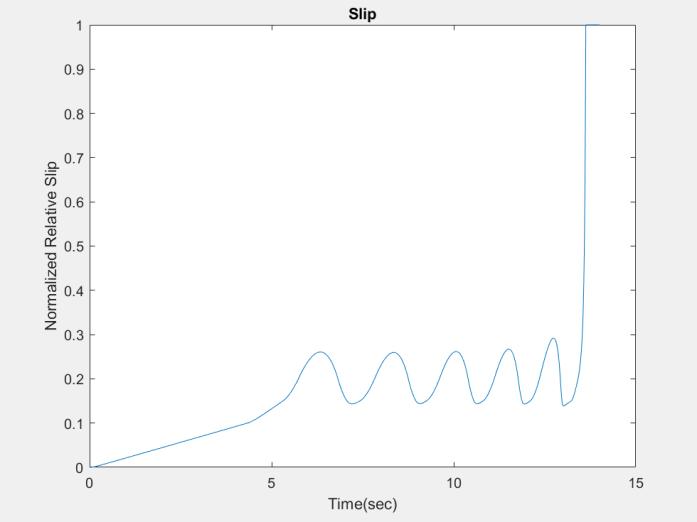
Chart -4:Slipratio
Stopping Distance: Chart-3 illustrates the distance traveled by the car during the process of braking. It demonstrates the effectiveness of the hydraulic brake systemandABSinachievingthedesiredstoppingdistance whilemaintainingtheconstantslipratio
Slip ratio:Chart-4showsthevariationinthe relative slip ofwheelsovertimeduringthebreakingevent.Ithighlights theeffectofbangbangcontrollerontheslipratio
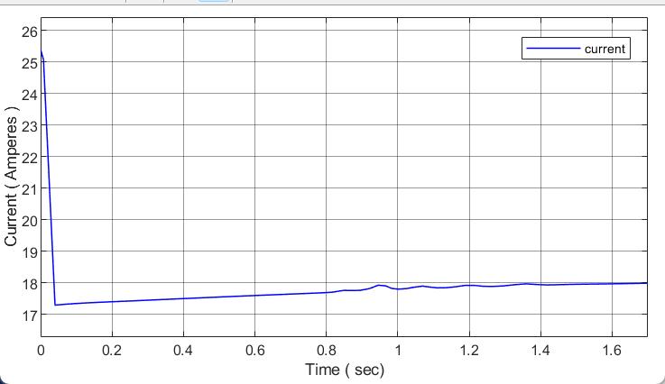
A MATLAB model for simulating and analyzing the behavior of an MR Fluid Disc Brake has been developed. By developing the relationship between the current, magnetic field and braking torque. Mathematical analysis of the MR Fluid Disc Brake is performed. The total shear stress in the brake increases as the magnetic field intensifies,leadingtothecessationoftherotatingdisc.To assess the behavior of the MR Fluid Disc Brake within a vehicle system, a Quarter Vehicle Model is utilized. The model considers various forces, including dynamic frictional force, rolling frictional force, and mass transfer during braking. Additionally, the integration of an Antilock Braking System (ABS) with MR Fluid brakes is achieved by designing a sliding mode controller that maintains a constant slip ratio of 0.2. This slip ratio corresponds to an appropriate current that has to be induced in the system for which the sliding mode controller has been utilized. The simulation is conducted using an initial vehicle velocity of 70 km/hr, and the resulting graphs of current, braking torque, wheel and vehiclespeed,andslipratioaregenerated.
International Research Journal of Engineering and Technology (IRJET) e-ISSN:2395-0056
Volume: 11 Issue: 10 | Oct 2024 www.irjet.net p-ISSN:2395-0072
Table -3: Parameters pertaining to MRB
Numberofcontact,N 4
Fluidgap(h) 0.1cm
radiusoftheouter brakedisc, 0.168m
radiusoftheinner brakedisc, 0.118m
MRfluidviscosity, 0.09Pas
Electricconstant,k 0.269Pam/A
Proportionalgain, 12.5x

Basiccoefficient, 1x
Speedeffect coefficient, 5x


The equation (5) and (6) can be rewritten using equation (2)and(3)as: (7) (8)


Scalingcoefficient, 2.237
Working of MRB can be defined using the following mathematicalanalysis[7]
3.2.1 Mathematical modeling of MR Fluid Brakes
The behavior of MR fluid can be approximated by the Binghamplasticmodel: (1)

Where is the yield stress developed due to the influenceofmagneticfield , istheconstantofplastic viscosityand istheshearrate


Brakingtorquecanbecalculatedusing: (2) (3) (4)
3.2.2 Vehicle modeling and sliding mode controller

Using Newton's law, the following equations can be derived: (5) where (6)


Where , , and

Thecontrolvariableslipratiocanbedefinedas: (9)
Fortheslidingmodecontroller,Slipratioischosenasthe slidingsurface.Thecontrollawcomesouttobe:

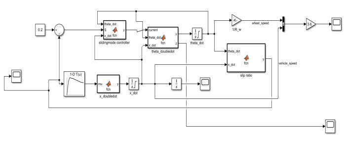
Themodelcanbebuiltonsimulink:
Preliminarily, chattering can easily be removed by creatingathinboundarylayerofthickness andreplacing by [8]


After implementing the saturated function following resultscanbeobtained:
International Research Journal of Engineering and Technology (IRJET) e-ISSN:2395-0056
-5 Current
AsseenfromChart-5andChart-6,chatteringstillpersists.
Chatteringisanundesirablephenomenonofoscillationsof finite amplitude and frequency. Chattering is the primary obstacle in implementing sliding control. Chattering is an undesirablephenomenonbecause[9]:
• Itleadstolowcontrolaccuracy
• Itcauseshighwearandtearofmechanicalparts
• ItcausesHeatlossesinelectricalcircuits
Therearemainlytworeasonsforchattering:
1. Itcanbecausedbyfastdynamics,whichareoften neglectedinanidealmodel
2. The second reason, which is the reason for chatteringinpreliminarydesign.Thereasonisthe
Volume: 11 Issue: 10 | Oct 2024 www.irjet.net p-ISSN:2395-0072 © 2024, IRJET | Impact Factor value: 8.315 | ISO 9001:2008
use of a digital controller (since it has a finite sampling rate). It’s known as discretization chatter
Hereamodifiedsaturatedfunctioncanbecreated[10]:

After implementing the modified saturated function followingresultscanbeobtained:
International Research Journal of Engineering and Technology (IRJET) e-ISSN:2395-0056
Volume: 11 Issue: 10 | Oct 2024 www.irjet.net p-ISSN:2395-0072
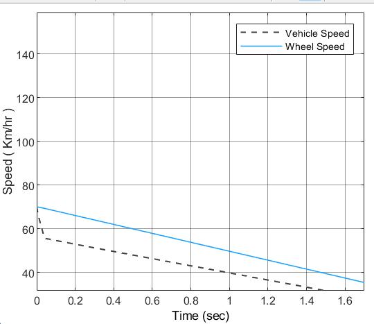
Chart -9 VehicleandWheelSpeed
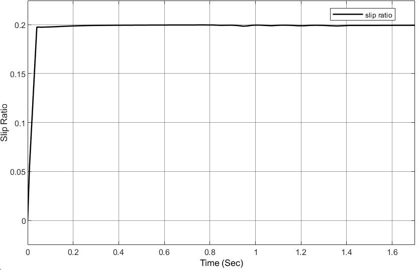
Chart -10 BrakingTorque
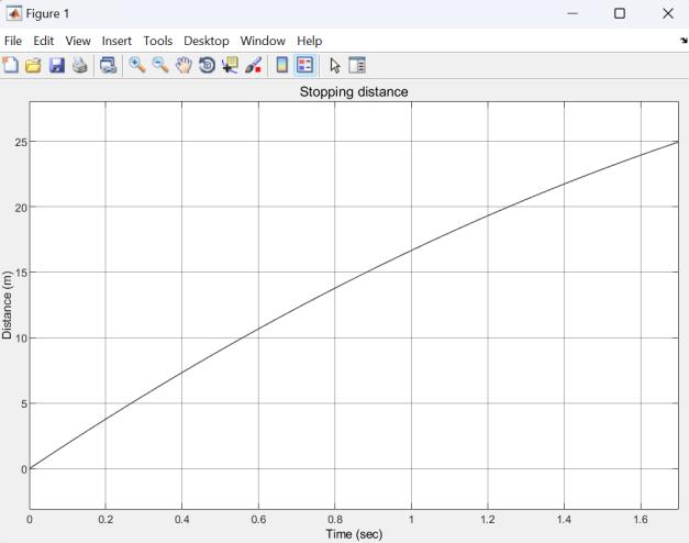
Chart -11 StoppingDistance
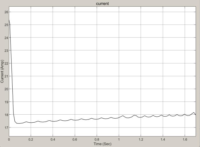
Current:Chart-7showsthevariationofcurrentovertime during the braking event. It highlights the control signal given by the sliding mode controller to keep a constant andoptimalvalueofslipratio.
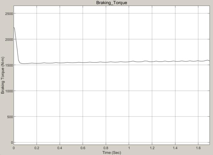
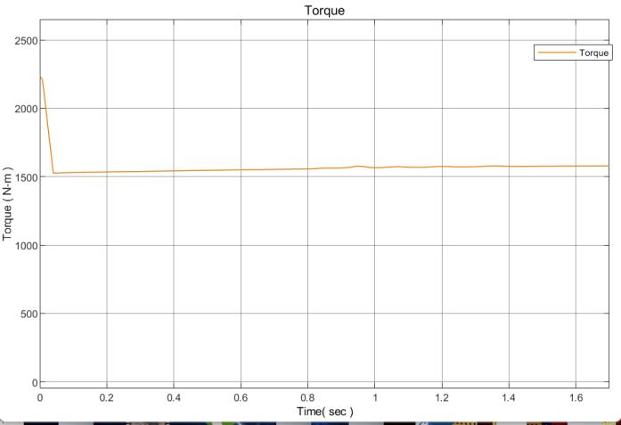
Braking Torque: Chart-8 illustrates the relationship betweenthebrakingtorqueappliedbytheMRfluidbrake and the resulting slip ratio. It demonstrates how the braking torque adjusts to keep a constant slip ratio of 0.2 throughoutthebrakingprocess.
Vehicle and wheel speed:Chart-9showsthevariationin vehicle speed and wheel speed over time during the braking event. It highlights the impact of the ABS control system and the MR fluid brake in controlling the wheel speedandpreventingwheellock-up.
Slip ratio:Chart-10showsthe variationinrelativeslip of wheels over time during the braking event. It highlights theeffectofslidingmodecontrollerontheslipratio
Stopping Distance: Chart-11 displays the distance traveled by the car during the process of braking. It demonstrates the effectiveness of the MR fluid brake and ABSsysteminachievingthedesired
The graph in Chart-11 displays the distance traveled by thecar
A comparative analysis between conventional hydraulic brakingandMR(magneto-rheological)fluidbrakescanbe conductedbygeneratinggraphsofslipratioasthecontrol variable, as well as measuring stopping time, vehicle speed, and wheel behavior during braking. These graphs provide valuable insights into the performance and effectiveness of the respective braking systems. By examining the generated graphs, several conclusions can bedrawnfromtheTable4:
• MR Fluid braking system has much less stopping time due to continuous control of torque in contrast with discontinuous control in conventionalhydraulicbrakes
• As previously mentioned, the stopping time is significantlyshorterinMRBwhichalsotranslates toamuchshorterstoppingdistancecomparedto CHBS (Conventional Hydraulic Braking System). This implies that the MRB system can bring the car to a complete halt in a shorter distance than the CBS system, indicating superior braking performanceandefficiency.
• CBS system, indicating superior braking performance and efficiency. Since MRB uses a sliding mode controller it has significantly
International Research Journal of Engineering and Technology (IRJET) e-ISSN:2395-0056
shorterrisingandsettlingtimethanCBS.Integral square error for MRB comes out to be 0.000475068whereasforCHBitcomesouttobe 0.126. Hence MRB has better controller performance
Table -4: Comparison between MRB and CHB on various parameters
Comparative analysis CHB MRB MRB(before chattering reduction)
Stoppingdistance 74m 26m 26m
Stoppingtime 14sec 2sec 2sec
Integralsquare error(ISE) 0.126 x x
IntegralTimeWeightedAbsolute Error(ITAE) 6.746 8 x x
5. Conclusion and Future Work
The MATLAB models of CHB and MRB were contrasted, which produced results revealing that MRB outperforms CHBS as the former can maintain an optimal slip ratio of 0.2 more effectively while the latter could not. The problem of chattering inherent in the SMC is solved by building a variable time-varying boundary layer around the switching surface. Graphs of current input, braking torque, stoppingdistance, vehiclespeed, and wheel speed havebeengeneratedthroughtheSimulinkmodel.
[1] Srikanth Sivaramakrishnan. Discrete Tire Modeling for Anti-lock Braking System Simulations. PhD thesis, 082013.
[2] KeremKarakoc.Designofamagnetorheologicalbrake systembasedonmagneticcircuitoptimization.2007.
[3] Pradeep P Phule. Magnetorheological (mr) fluids: principles and applications. Smart Materials Bulletin, 2001(2):7–10,2001.
[4] M. Lokander and B. Stenberg. Magnetorheological Devices,pages165–169.122006.
[5] Jung Sohn, Juncheol Jeon, Hung Nguyen, and S. Choi. Optimal design of disc-type magneto-rheological brake for mid-sized motorcycle: Experimental evaluation. Smart Materials and Structures, 24, 08 2015.
[6] MohamedWatanyetal.Performanceofaroadvehicle with hydraulic brake systems using slip control
Volume: 11 Issue: 10 | Oct 2024 www.irjet.net p-ISSN:2395-0072 © 2024, IRJET | Impact Factor value: 8.315 | ISO 9001:2008
strategy. American Journal of Vehicle Design, 2(1):7–18,2014.
[7] EdwardJ.Park,DilianStoikov,LuisFalcaodaLuz,and Afzal Suleman. A performance evaluation of an automotive magnetorheological brake design with a sliding mode controller. Mechatronics, 16(7):405–416,2006.
[8] Eliezer Kreindler. Advanced control system design : By b. friedland. prentice hall (1996). isbn 0-13014010-4.Autom.,33:485–486,1997.
[9] Vadim Utkin. Chattering problem in sliding mode controlsystems.volume39,pages1–1,062006.
[10] P.KachrooandM.Tomizuka.Chatteringreduction anderrorconvergenceinthesliding-modecontrolofa class of nonlinear systems. IEEE Transactions on AutomaticControl,41(7):1063–1068,1996.