
International Research Journal of Engineering and Technology (IRJET) e-ISSN:2395-0056
Volume:11Issue:10|Oct 2024 www.irjet.net p-ISSN:2395-0072

International Research Journal of Engineering and Technology (IRJET) e-ISSN:2395-0056
Volume:11Issue:10|Oct 2024 www.irjet.net p-ISSN:2395-0072
Ch. Sai Amith1 , Ch. Ratnam 2
1PG scholar, Department of mechanical engineering, Andhra university, Visakhapatnam, India
2Professor, Department of mechanical engineering, Andhra university, Visakhapatnam, India
Abstract - A Quadcopter is a sophisticated mechatronic device characterized by complex dynamics, relying on controlling six degrees of motion using thrust generated by propellers driven by DC motors. The primary objective of this study is to conduct a comprehensive thrust force analysis comparing a conventional three-blade propeller with a toroidal propeller, assessing the thrust force generated by each design under varying angular speeds and velocities.
To achieve this, 3D CAD models of both the three-blade conventional propeller and the toroidal propeller were meticulously designed using Onshape software. These models were then imported into SimScale software for fluid flow simulation, where the aerodynamic characteristics over the propellers were analysed under different angular speeds and free-stream velocities. The simulation data provides insights intohoweachpropeller designaffectsthrustforcegeneration and overall efficiency.
Additionally, this study evaluates and compares the efficienciesofbothpropellertypes.Efficiencymetricsconsider factors such as thrust force output relative to power input. By systematically comparing these aspects across various operating conditions, the study aims to highlight the performance advantages and potential drawbacks of each propeller design in diverse flight scenarios.
This outlines a structured approach to quantify and analyse the thrust force capabilities of conventional threeblade propellers versus toroidal propellers using SimScale software. The findings are expected to contribute to advancements in propulsion technology, improving the efficiency and effectiveness of aerial vehicles, marine vessels, and industrial machinery.
Key Words: 3D CAD models, Aerodynamic characteristics, Angular speeds, Conventional threeblade propeller, Efficiency, Fluid flow simulation, Onshapesoftwareetc
1.INTRODUCTION
Theintroductionofthisthesisprovidesanoverview oftheresearchonpropellerdesignforquadcopters,focusing ontheroleofpropellersinenhancingUAVperformance.It highlightsthegrowingneedforefficientpropulsionsystems as UAVs become integral in industries like photography,
logistics,andsurveillance.Thestudyaddressesthelackof comprehensive research comparing traditional 3-blade propellerstotoroidaldesigns,particularlyintermsofthrust and efficiency. This sets the foundation for the research objectives, which include a detailed analysis of both propellertypesusingadvancedsimulationtoolstooptimize theirperformance.
The problem statement emphasizes the need for improvedpropellerdesignstomeettherisingdemandsfor UAV efficiency and performance. While conventional propellers are widely used, they may not always provide optimal thrustorefficiencyundervaryingconditions. The study seeks to address this gap by comparing the aerodynamic and performance characteristics of conventional and toroidal propellers, particularly under different operational scenarios. The research will use advanced3Dmodellingandfluidflowsimulationstoanalyse the propellersand provide practical insights for propeller designinUAVapplications.
Thesignificanceoftheresearchliesinitspotential toadvanceUAVtechnologybyofferingdata-driveninsights into propeller dynamics and performance. By focusing on bothconventionalandtoroidaldesigns,thisstudy aimsto guidefuturepropellerselectionandoptimizationforvarious UAV applications. The scope includes designing and simulatingpropellersusingCADandCFDsoftware,followed byanevaluationofthrust, efficiency,andpotential design improvements, contributing to the development of more efficientUAVsystemsacrossdiverseindustries.
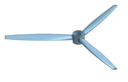
The design process for the 3-blade conventional propellerbeginsbysettingupaprojectinOnshape,ensuring consistentunitsofmeasurementforaccuratemodelling.The overalldimensionsaredefined,withapropellerdiameterof 6inches(152.4mm)andapitchof4inches(101.6mm).The initialgeometryiscreatedbydrawingconcentriccircleson thetopplanetoformthehubandbladebase,followedby extruding these shapes to establish the blade profiles and hubgeometry.
International Research Journal of Engineering and Technology (IRJET) e-ISSN:2395-0056
Volume:11Issue:10|Oct 2024 www.irjet.net
Next,additionalplanesaregeneratedtodefinethe bladeprofilesatdifferentpositionsalongthepropeller.On these planes, the chord lengths and angles of the blade sectionsaredefined,withairfoilprofilesappliedtoensure properaerodynamiccharacteristics.UsingtheNACA2412 seriesprofile,thebladesectionsarethenloftedtogetherto formasmoothtransitionfromtheroottothetip.Theblade is connected to the hub using a fillet to reduce stress concentrationsandimproveaerodynamicperformance.
Oncethebladesareformed,thecentralhubcutout is created to allow for mounting, and the blade pattern is generated,arrangingthethreebladesevenlyusingacircular pattern.Finally,thedesignisrefinedbyapplyingfilletsand chamferstosmoothsurfaces,particularlyattheleadingand trailing edges of the blades, to reduce drag. These final touches ensure that the propeller meets the design specificationsandisoptimizedforperformance
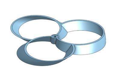
Thedesignprocessforthetoroidalpropellerbegins withdefiningtheoveralldiameterof6inches(152.4mm), ensuringthatthepropellersharessimilarspecificationswith theconventionaloneforaccuratecomparison.Aftersetting up a new project in the CAD software, the units are configuredtomillimetres(mm)forlineardimensionsand degreesforanglestomaintainconsistencythroughoutthe design. The initial step involves creating the hub by sketching a 12 mm diameter circle on the top plane and extrudingittoaheightof10mm,formingthecentralhub fromwhichthebladeswillextend.
Next,constructionanddesigncirclesaredrawnon thesameplanetodefinetheouterboundaryofthepropeller and its profile. A helix is generated from the centre of the hub, serving as a guiding path for shaping the propeller blades.Thehelix,withaheightof10mm,ensuresthatthe bladesfollowthecorrectaerodynamicpath.TheSweeptool isthenusedtoformthepropeller bladesbysweepingthe designcirclealongthehelixcurve,generatinga3Dshape. TheShelltoolisappliedtothissweep,creatinga2mmthick hollow structure, which forms the primary aerodynamic surfaceofthetoroidalpropeller.
Followingthis,theCircularPatterntoolisusedto replicatethesweptbladeprofilearoundthehub,placingtwo additional blades at 120-degree intervals. Unnecessary sections of the geometry are removed using the Split operation,leavingthedesiredpropellershape.Finally,the BooleanAddoperationmergesthebladeswiththehub to createaunifiedstructure,andadditionalfilletsandchamfers areappliedtoimprovestructuralintegrityandreducestress concentrations.Afterverifyingtheoverall dimensions,the toroidalpropellerisrefinedandoptimizedforperformance, readyforfurtheranalysisandsimulation.
p-ISSN:2395-0072
Figure 1 and Figure 2 depict the CAD models of the conventional 3-bladepropellerand the toroidal propeller, respectively. Both models were created using Onshape, adhering to the design specifications and optimized for performanceevaluation
This chapter explores the CFD simulations performed on the 3-blade conventional and toroidal propellers using the SimScale platform, aiming to analyse andcomparetheiraerodynamicperformance, focusing on keymetricslikethrust,torque,andefficiency.Theprocess began with the accurate import of 3D CAD models into SimScale, followed by the creation of rotating and static domains to capture the interaction between the propeller blades and the surrounding air. The rotating domain, represented as a cylindrical volume around the propeller, simulatesthemotionoftheblades,whilethestaticdomain handlesthesurroundingfluid.
TheMRF(MultipleReferenceFrame)methodwas employedforefficienthandlingofthepropeller'srotational effects, alongside selecting the k-ω SST turbulence model andsteady-stateconditionstoensurerealisticanalysis.Air wasassignedastheworkingfluid,andtheinitialconditions setthefluidatresttoprovideastablebaseline.
Criticalboundaryconditionswereappliedtoreflect real-worldoperationaldynamics.Avelocityinletcondition wasdefinedatthedomaininlettosimulateairflowtoward thepropeller,whileapressureoutletconditionwassetto0
International Research Journal of Engineering and Technology (IRJET) e-ISSN:2395-0056
Volume:11Issue:10|Oct 2024 www.irjet.net p-ISSN:2395-0072
Pa at the exit to ensure atmospheric pressure. Slip walls were used for the static domain to minimize friction and simulateanopen-airenvironment,whileno-slipwallswere applied to the propeller surfaces to accurately model the interactionbetweenthebladesandthesurroundingair.
Themeshwascarefullyrefined,withafinenessof 8.1 and physics-based meshing techniques ensuring accuracyandcomputationalefficiency.Thiswell-structured simulation setup provides a solid foundation for the subsequentcomparisonoftheaerodynamicperformanceof theconventionalandtoroidalpropellers.
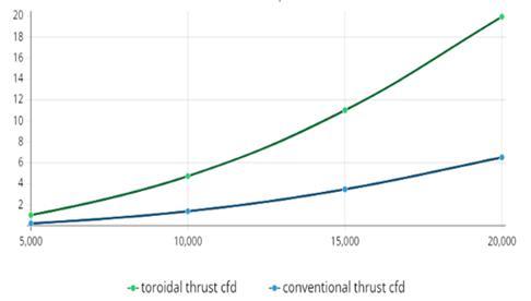
All the results from the simulations are presented in graphical form, providing a clear and comprehensive visualization for both the conventional and toroidal propellers
4.1 Thrust results comparison
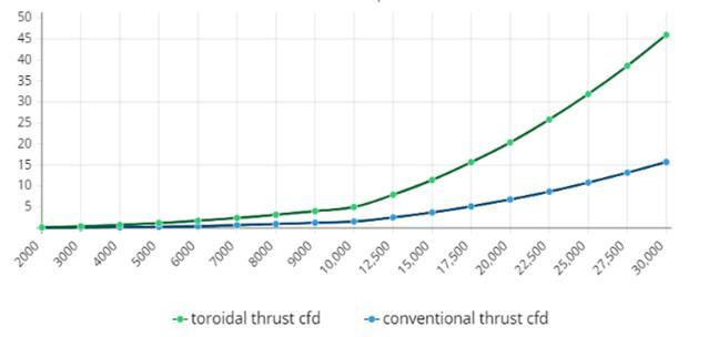
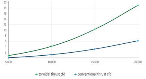
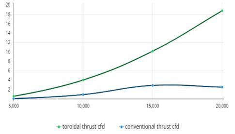
: Illustrating a graph between thrust vs rpm at 8 m/s
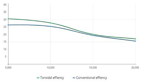
4.2 Efficiency results comparison
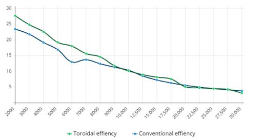
Chart-5: Illustrating a graph between efficiency vs rpm at 2 m/s
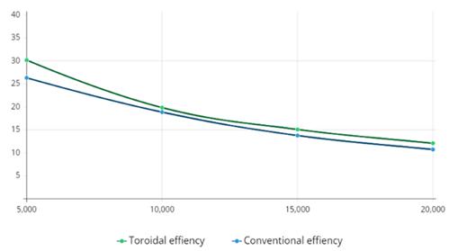
Chart-6: Illustrating a graph between efficiency vs rpm at 4 m/s
International Research Journal of Engineering and Technology (IRJET) e-ISSN:2395-0056
Volume:11Issue:10|Oct 2024 www.irjet.net p-ISSN:2395-0072
: Illustrating a graph between efficiency vs rpm at 6 m/s
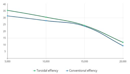
: Illustrating a graph between efficiency vs rpm at 8 m/s
The research conducted on the performance of conventional and toroidal propellers has provided significantinsightsintotheiroperationalcharacteristicsand efficiencies. Key findings indicate that toroidal propellers consistently outperform conventional designs in various conditions, demonstrating superior thrust and efficiency. This underscores the importance of innovative designs in optimizingpropulsionsystems.Thestudyalsohighlighted that increasing the number of blades enhances thrust generation for both propeller types, indicating that blade designisacriticalfactorinachievingoptimalperformance.
These conclusions not only align with existing literature but also have practical implications for applications in drone technology and other fields where propulsionefficiencyisparamount.Basedonthesefindings, several recommendations emerge for future propeller design. First, designers should prioritize toroidal configurations for high-performance applications, such as racingdrones.Second,increasingbladecountcanenhance thrustgeneration,sodesignsshouldexploreconfigurations withthreeormorebladeswhilebalancingthrustwithdrag. Additionally,focusingonadvancedaerodynamicprofilesand testing varied blade geometries will be crucial for
maximizingefficiency.Materialselectionisalsoimportant, withapreferenceforlightweight,high-strengthmaterialsto improve thrust-to-weight ratios. Finally, while computationalsimulationsarevaluable,real-worldtestingis essential to validate findings and ensure designs perform wellundervariousconditions.
Overall, the demonstrated advantages of toroidal propellers could pave the way for their adoption in more advanced aerial vehicles, contributing to enhanced operational capabilities and advancements in the field of aerialpropulsiontechnology.
[1] Paul G. Fahlstrom, Thomas J. Gleason, Introduction to UAV Systems,4thEdition,Wiley,2012
[2] RandalW.Beard,TimothyW.McLain, Small Unmanned Aircraft:TheoryandPractice,PrincetonUniversityPress, 2012
[3] John A. C. Frizzell, Drones: A Very Short Introduction, OxfordUniversityPress,2018
[4] Andrew J. H. MacKenzie, The Handbook of Drone Photography: Techniques and Equipment,Elsevier
[5] BarnesW.McCormick, Aerodynamics, Aeronautics, and Flight Mechanics,2ndEdition,JohnWiley&Sons,1995
[6] Wu,X.,Li,Y.,&Zhao,Z.(2022).Aerodynamicmodeling of quadcopter UAV with dynamic inflow and wake turbulenceeffects. ChineseJournalofAeronautics,35(3), 276-291.DOI:10.1016/j.cja.2022.06.001.
[7] Czyż,Z.,Karpiński,P.,Skiba,K.,&Wendeker,M.(2022). Wind tunnel performance tests of the propellers with different pitch for the electric propulsion system. Sensors,22(1),2..
[8] Mohamed, A., & Abdalla, S. (2021). A review of the dynamicsandcontrolofquadcopters. AerospaceScience and Technology, 117, 106921. DOI: 10.1016/j.ast.2021.106921.
[9] Zhang, L., & Wu, X. (2021). Propeller aerodynamic analysis and optimization for UAV efficiency enhancement. Journal of Aerospace Engineering,35(4), 04021077. DOI: 10.1061/(ASCE)AS.19435525.0001389.
[10] Wang,J.,&Hu,J.(2022).Influenceofrotorbladedesign on the aerodynamic performance of UAVs. Aerospace Science and Technology, 118, 107072. DOI: 10.1016/j.ast.2022.107072.
[11] Lee, S., Park, J., & Kim, H. (2021). Propeller wake interferenceinmulti-rotordrones:Anexperimentaland
International Research Journal of Engineering and Technology (IRJET) e-ISSN:2395-0056
Volume:11Issue:10|Oct 2024 www.irjet.net p-ISSN:2395-0072
numerical study. Journal of Fluid Mechanics, 927, A1. DOI:10.1017/jfm.2021.533.
[12] Aditya, K., et al. (2023). Performance of 3D Printed Conventional and Toroidal Propellers. International JournalofScientificResearch.DOI:10.32628/IJSRSE.
[13] Wu, X., et al. (2023). Aerodynamic and Aeroacoustic AnalysisofToroidalPropellers.InternationalJournalof Aerodynamics.
[14] Žagar,L.,&Jamšek,M.(2023).ComparisonandAnalysis ofToroidalandClassicPropellers.ERK'2023Conference Proceedings.
[15] Gabriel, I., & Simion, I. (2023). Performance of 3D PrintedConventionalandToroidalPropellerforSmall Multirotor Drones. Journal of Industrial Design and EngineeringGraphics,18(1),27-32.
[16] Leishman,J.G.PrinciplesofHelicopterAerodynamics. 2nded.,CambridgeUniversityPress,2006.
[17] McCormick,B.W.Aerodynamics,Aeronautics,andFlight Mechanics.2nded.,JohnWiley&Sons,1994.
© 2024, IRJET | Impact Factor value: 8.315 | ISO 9001:2008 Certified