
International Research Journal of Engineering and Technology (IRJET) e-ISSN: 2395-0056
Volume: 11 Issue: 10 | Oct 2024 www.irjet.net p-ISSN: 2395-0072


International Research Journal of Engineering and Technology (IRJET) e-ISSN: 2395-0056
Volume: 11 Issue: 10 | Oct 2024 www.irjet.net p-ISSN: 2395-0072
Eng. Ali Adnan Ajamiah1 , Dr. Heitham Issa2
1Marine Engineer and Master Student, Department of Maritime Engineering, Faculty of Mechanical and Electrical Engineering, Tishreen University, Latakia, Syria.
2Associate Professor, Maritime Engineering Department, Faculty of Mechanical and Electrical Engineering, Tishreen University, Latakia, Syria.
Abstract - The research reviews the designs of high speed boats hulls and the features and characteristics of each one, leadingtotheselectionanddesignofasuitablemodelusingthe Maxsurf program with dimensions suitable for the marine market and with a monohull type (Planning Hull), due to its goodspeedandmaneuvering characteristics, lower resistance values, and less disturbance on the water surface. After that, a preliminary drawingof the general arrangement plan andthe tank distribution plan was made, and stability calculations were conducted on the boat designed according to the recommendations of the Maritime Classification Society, to deduce the behavior of the hull and the resulting stability values under different loading cases.
Key Words: high-speed boat, boat stability, general arrangement,monohull,planninghull.
With the rapid development in ship design and construction, high-speed boats occupy an important place in development laboratories so that the studied structures achieve the required speeds with lower capacities by reducingthevaluesoftheresistancesaffectingtheboatdue to the better streamlined shape that is compatible with internationalclassificationrules,asmodernmodelsseekto achieve high quality and reliability. For this reason, many studieshave addressed the topics related to fast boats and the difficulties facing designers in this field. Some of them discussed the initial hydrodynamic characteristics of slender structures and gave the schematic equations and experimental methods that show the values of the wetted surface areas, pressure centers, the angle of the ship's entry, and the longitudinal tilt resulting from the increase inspeed,inadditiontosettingthepredictiveequationsthat achieve the horsepower requirements and appropriate operating values in accordance with the studied structure witha setofillustrativeexamplesanddigital diagrams[1]. Someofthemalsopresentedtheproblemsfacingdesigners in producing slender marine structures under the lowest values of effective resistance due to the complexity in determining the nature of fluid flow and its effect on the structure and the role of wet and free surfaces and the mutual influence between them, and did not Predicting resistance values was a simple matter, as a model was
designed and placed in a test basin, and the results were collected within the research. A set of equations were extracted that give the initial prediction of resistance valuesandtherelationshipbetweenthestreamlinedshape of the hull and achieving the highest possible speed in order to improve the actual operation of the ship under different sailing conditions [2]. The various investment conditions for high-speed boats were also discussed according to a studied model that achieves the required speed and economic efficiency, in addition to determining the appropriate size of the submerged part and presenting methods for improving flow. The author found that the Planning hull pressures increase in the front part of the hull,butdecreaseandbecomenegativeinthe aft.Hefound that the thickness of the boundary layer increases in the direction of flow and decreases with increasing model speeds. He found that the measured speeds outside the boundary layer were greater than the free flow in the aft part of the hull, indicating acceleration from the front position. The research emphasized the importance of adding side fins to improve stability according to the results of the flow analysis around the studied hull [3]. Some research has dealt with developments in models of civil and military high-speed boat structures, where calculatingspeedand energyisa majortopicfor designing a model that achieves compatibility between structureand power. The research programmed both the Savitsky equations,whicharethemostwidelyusedmethod,andthe CAHI equations used in military models to predict resistance values. The study includes a set of variables related to the main dimensions, the movement of the boat, andtheinfluencefactors.Theaimofthisstudyistopresent the CAHI method to the community of high-speed boat designers [4]. The relationship between the deadrise angle and the resulting resistance was studied, in addition to creating a database for the studied model structures. The initial results indicated that the design with a large deadrise angle showed less resistance compared to the reference boat design, as the hull resistance decreased by 16.87% at a deadrise angle of 30 degrees compared to the largest resistance at any other elevation angle [5]. The Syrian Arab Republic lacks this type of boats, except for some small fishing and pleasure boats. Therefore, it is necessary to determine the appropriate model for work in

Volume: 11 Issue: 10 | Oct 2024 www.irjet.net p-ISSN: 2395-0072
Syrian territorial waters, while specifying the available capabilities and the type of materials used in construction and their role in improving the actual return and the requiredefficiency.
The importance of the research stems from the necessity of finding the appropriate model due to the urgent need to design and apply this model with appropriatedimensionsfromtheeconomicandinvestment pointofview,andwithgoodstabilitycharacteristics,andto establish this model as a basic structure for establishing marine guard groups with national expertise to secure the missionofprotectingterritorialwaters,andemployingthis modelforvariouspurposessuchas:
•Combatingsmugglingoperations
•Combatingpiracyoperations
•Combatingillegalimmigrationoperations
• Search and rescue operations and rapid response (to assist boats and other ships or assist individuals in the water)
•Periodiccoastalpatrolstoprotectmaritimeborders.
1.2
The methods and materials used in this research are as follows:
-TheMaxsurfprogramwithitsvarioussections,whichare Maxsurf Modeler, Maxsurf Resistance, and Maxsurf Stability,todesignthehullandconductinitialtestsonit.
- The AutoCAD program to draw the General Arrangement planforthedesignedboat.
- The Excel program to help draw some tables and clarify somegraphs.
1.3 Research Methodology
The methodology followed in this research is analytical withintheMaxsurfprogramenvironment.
The design process began with a major analysis of some similarboatsthathadbeendesignedandbuiltpreviously:
Table -1: Listofsimilardesigns
Afteranalyzingthevaluesofthemaindimensionalratiosof thepreviousdesignsandidentifyingtheircharacteristics,and based on the famous geometric similarity theory, it was assumed that the appropriate dimensions that achieve the requiredgoalfallwithinthefollowingareas(Table2):
Table-2: Maindimensionsofthedesignedboat
(m)
25-35 (kn)
(m)
(m)
After researching the range of available high-speed boat designs,threedifferentDisplacementhull,Semi-displacement hull and Planning hull designs were selected for initial testing:

International Research Journal of Engineering and Technology (IRJET) e-ISSN: 2395-0056
Volume: 11 Issue: 10 | Oct 2024 www.irjet.net p-ISSN: 2395-0072

Fig-1:Displacementhull
http://trawlerschoolcharters.com/blog/wpcontent/uploads/2013/09/boatlinessmall.jpg.

Fig-2: Semi-displacementhull
https://www.sciencedirect.com/science/article/pii/S2092 678216304083
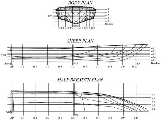
Fig-3: PlanningVhull
https://www.mdpi.com/2411-9660/6/6/105
Thegeneratedwavefieldforeachofthepreviousdesignswas calculatedusingtheResistanceMaxsurfprogram.Theresults oftheanalysisareshowninchart(1).chart(1)showsthat theDisplacementhullcreateswaveswithahigherheightthan its counterparts in the studied group, and thus greater turbulence on the water surface, while we note that the
2024, IRJET | Impact Factor value: 8.315 |
Planning V hull is more stable, which gives it good maneuveringcharacteristicsinharshconditionsandlower resistancevalues,andtheabilitytoreachhigherspeedsand createverylowwavesinthelowerandmediumspeedrange.
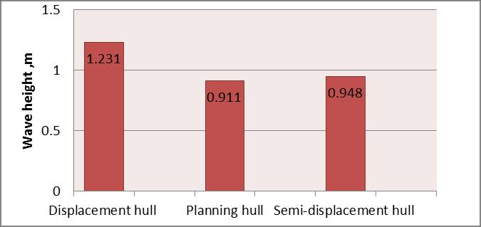
Chart-1 : Comparisonoftheheightofthewavesgenerated bythethreemodels(EXCEL)
Afterconductingthepreviousanalysis,theboatwasdesigned usingtheMaxsurfprogramwitharelativelyslenderPlanning hull with a V-shaped bow to achieve good speed and maneuverabilitysuitablefor varioussailingconditionsand coastguardmissionswithinterritorialwaters.Itisdesigned entirelyfromresistantfiber.


International Research Journal of Engineering and Technology (IRJET) e-ISSN: 2395-0056
Volume: 11 Issue: 10 | Oct 2024 www.irjet.net p-ISSN: 2395-0072
Figure(6)showsthegeneralarrangement plan(GA)ofthe designedboat,whichwasdrawnusingAutoCADsoftware:


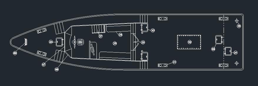
Fig-6: Generalarrangementplan )AutoCADSoftware(

Fig-7: Tanksdistributionplan(Maxsurf)

International Research Journal of Engineering and Technology (IRJET) e-ISSN: 2395-0056
Volume: 11 Issue: 10 | Oct 2024 www.irjet.net p-ISSN: 2395-0072
Fig-8: Bodyshapecoefficientcurves (MaxsurfStability)

Fig-9: Hydrostaticcurvesoftheboat (MaxsurfStability)
Fig-10: KNcurves (MaxsurfStability)
Stability studies were conducted on the boat designed in this research at four loading conditions (according to the recommendations of the classification societies):
1-LightshipCondition.
2-Mid-tripCondition.
3-DepartureCondition.
4-ArrivalCondition.
Theresultingstabilityvalueswereverifiedtobeinlinewith the safe values of the International Maritime Organization (IMO) and the marine classification societies (CS) by comparing them with the IMO standard (A749) included implicitlyintheMaxsurfprogram.
5.1 First case: Lightship Condition
Table-4:LightshipLoadCase (MaxsurfStability)
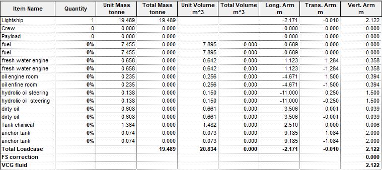

Fig-11: GZcurveat0%loadcondition (MaxsurfStability)

International Research Journal of Engineering and Technology (IRJET) e-ISSN: 2395-0056
Table-5:IMOstandardstestforstabilityat0%load condition(MaxsurfStability)

5.2 Case 2: Mid-trip Load Condition
Table-6: Mid-tripLoadCase (MaxsurfStability)

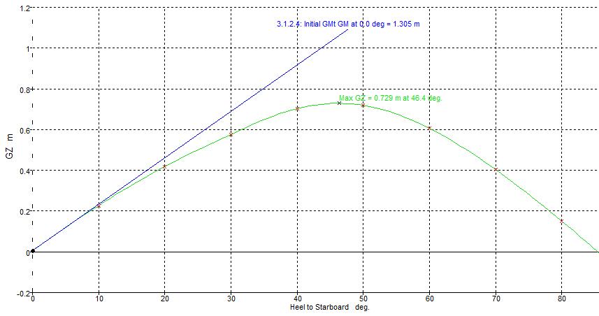
Fig-12:GZcurveat50%loadcondition (MaxsurfStability)
Table-7:IMOstandardstestforstabilityat50%load condition(MaxsurfStability)

5.3 Case 3: Departure Condition
Table-8: DepartureLoadCase (MaxsurfStability)


Fig-13: GZcurveatdeparturestatus(MaxsurfStability)
Volume: 11 Issue: 10 | Oct 2024 www.irjet.net p-ISSN: 2395-0072 © 2024, IRJET | Impact Factor value: 8.315 | ISO 9001:2008 Certified

International Research Journal of Engineering and Technology (IRJET) e-ISSN: 2395-0056
Volume: 11 Issue: 10 | Oct 2024 www.irjet.net p-ISSN: 2395-0072
Table-9: IMOstabilitystandardstestatdeparturestatus (MaxsurfStability)

5.4 Case 4: Arrival Condition
Table-10: ArrivalLoadCase (MaxsurfStability)
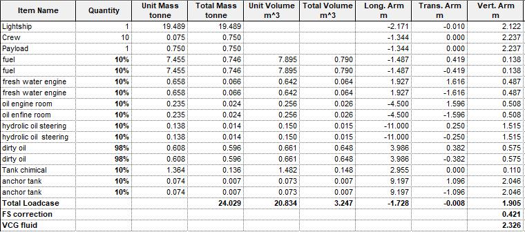

Fig-14: GZcurveatarrivalstatus(MaxsurfStability)
Table-11: IMOstabilitystandardstestatarrivalstatus (MaxsurfStability)

•Displacementhull createhigher wavesandcausegreater disturbanceonthewatersurfacecomparedtoothermodels studied.
• Tests according to IMO and CS rules programmed within MAXSURFsoftwareshowedthesafetyofthedesignedboat.
•Weconcludefromtheresultingstabilityratiosoftheboat theimportanceoftheparametervaluesthatwerechosenand thecorrectnessofchoosingthePlanninghull,whichshowed goodstabilitypropertiesunderdifferentloadingconditions.
• It is recommended in future studies to conduct stability calculationsincaseofdamage,sothatthehullisdividedinto several sectors, in order to know the behavior of the hull whenasinkingoccursinoneofthesectors.
•Itis recommended tostudythe effect of installinglateral stabilizationwingsontheboat'sstability.
[1] DanielSavitsky,Hydrodynamic DesignofPlanningHulls, MarineTechnology,1964.
[2] SiuC.Fung(AM)," ResistanceandPoweringpredictionfor Transom Stern Hull Forms During Early Stage Ship Design, High-Speed Displacement Hull", SNAME Transactions,Vol.99,1991.

International Research Journal of Engineering and Technology (IRJET) e-ISSN: 2395-0056
Volume: 11 Issue: 10 | Oct 2024 www.irjet.net p-ISSN: 2395-0072
[3] ESAMUDDIN HAMIDON, "Planning Craft-Small Craft Technology",UniversityTechnologyMalaysia,2009.
[4] Panagiotis G. Alourdas, planning Hull Resistance calculation ,The CAHI Method, SNAME Greek Section , 2016
[5] Aditya Rio Prabowo & Evan Martono,'' Effect of Hull Design Variation on The Resistance Profile and Wave Pattern , Patrol Boat'', School of Engineering, Taylor's University,vol.17,No1,2022.
[6] IMO, International Code on Intact Stability, United Kingdom:CPIBooksLimited,2009.
[7] Sun,H.;andFaltinsen,O.M, Numerical study ofplanning vessels in waves. Journal of Hydrodynamics, Ser. B, 22(5)Supplement1,(2010),468-475.
[8] https://www.damenmc.com/.
[9] Myung-IlRoh,Kyu-YeulLee,ComputationalShipDesign
[10] ChakrabortyS, Ship Stability – Understanding curves of static stability, 2017