International Research Journal of Engineering and Technology (IRJET) e-ISSN: 2395-0056
Volume: 11 Issue: 10 | Oct 2024 www.irjet.net p-ISSN: 2395-0072


International Research Journal of Engineering and Technology (IRJET) e-ISSN: 2395-0056
Volume: 11 Issue: 10 | Oct 2024 www.irjet.net p-ISSN: 2395-0072
Suhail Raza
1 ,
Prashant Vashisht
2
1Student of Bachelor of Technology in Civil Engineering, Lingaya’s Vidyapeeth, Faridabad, India
2Assistant Professor, Lingaya’s Vidyapeeth, Faridabad, India ***
Abstract - Thispaperpresentsthedesignanddetailingofa G+8 reinforced cement concrete (RCC) framed structure withandwithoutshearwallsusingSTAADProsoftware.The structure is located in Delhi, India, with a height of 27 meters, using concrete grade M25 and steel grade Fe415. The study focuses on the comparative performance of the structure under lateral loads due to seismic activity in Delhi's seismic zone (Zone IV). A comparative analysis is performedwithrespectto baseshear,deflection,andrisk assessment using both tabular and graphical representations.
Key Words: Size G+8 RCC Structure, Shear Walls, STAAD Pro,SeismicAnalysis,BaseShear,StructuralPerformance, RiskAssessment.
1. INTRODUCTION
Earthquake Zoning of India
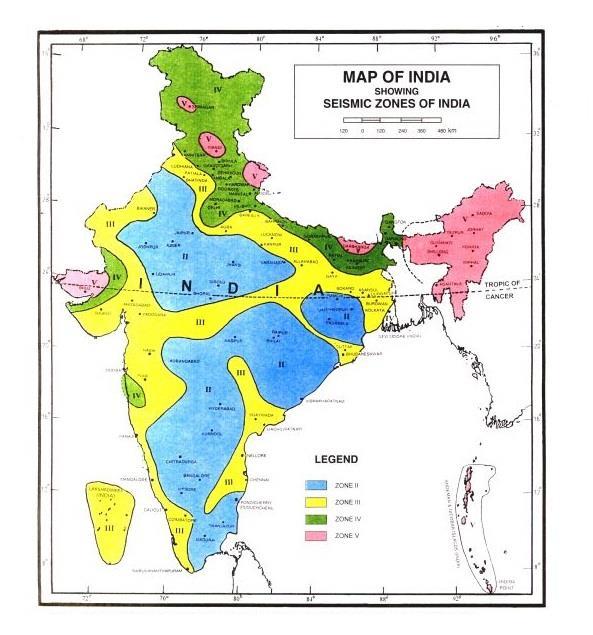
Indiahasahistoryofmajorearthquakes.Themainreason forthehighfrequencyofearthquakesisthattheIndianplate ismovingtowardsAsiaatarateof47millimetresperyear. GeographicalanalysisofIndiashowsthatabout54%ofthe landisvulnerabletoearthquakes.AccordingtoWorldBank and United Nations reports, about 200 million urban dwellersinIndiaareexpectedtobeaffectedbystormsand earthquakes by 2050. The latest version of the seismic zoningmapofIndiagivenintheIndianSeismicDesignCode [IS1893(Part1)2002]hasdividedIndiaintofourseismic levelsbasedonregionalfactors.Inotherwords,theseismic zoning map of India divides India into 4 seismic zones (Zones II, III, IV and V) as opposed to the earlier version where the seismic zoning of India had V to VI zones. Accordingtothecurrentzoningmap,ZoneVhasthehighest levelofseismicactivity,whileZoneIIhasthelowest.
ThisDelhi,beinginSeismicZoneIV,ispronetomoderateto high seismic activity. The structural design of high-rise buildings needs to address the safety concerns caused by seismic forces. Shear walls are used to provide additional stiffness to resist lateral forces, improving the overall stability of the building. In this study, the structure is analysed with and without shear walls to understand the effect of these elements on the stability of an RCC framed structure

2.1 Shear Wall
Shearwallsaredesignedtoresistwindandseismicloads. ShearwallsaredesignedbytheInternationalBuildingCode andtheInternationalResidentialCode.Theplaneofthewall is parallel to the shear walls. The shear walls and other verticalelementsofthesystemareresistiblebecauseofthe Collectors.Shearwallsusedinthestudyanalysisconsistsof reinforcedconcretewalls.
2.2 Building Details
Number of Stories:G+8(Groundfloor+8floors)
Height:27meters
Location:Delhi,India
Seismic Zone:IV(IS1893:2016)
Soil Type:Mediumsoil(TypeIIasperISCode)
Storey Height:3meters

International Research Journal of Engineering and Technology (IRJET) e-ISSN: 2395-0056
Volume: 11 Issue: 10 | Oct 2024 www.irjet.net p-ISSN: 2395-0072
2.2 Material Properties
Concrete Grade:M25
Steel Grade:Fe415
Density of Concrete:25kN/m³
Density of Masonry:20kN/m³
2.3 Design Parameters
Minimum Base Shear:933.07kN
Design Base Shear:4373.8kN
Importance Factor:1.2(IS1893:2016)
Response Reduction Factor (R): 5 (with shear walls),3(withoutshearwalls)
2.4 Software Used
Structural Analysis and Design:STAADPro
Design Codes:IS456:2000, IS1893:2016,IS875 (PartI&II)
3 STRUCTURAL MODELLING
3.1 Modelling in STAAD Pro
ThestructurewasmodelledandanalyzedusingSTAADPro, consideringdifferentloadcombinationsforbothgravityand seismic loads as per IS 1893:2016. Two different models werecreated:
1. Model 1:RCCframedstructurewithoutshearwalls.
2. Model 2:RCCframedstructurewithshearwalls.
3.2 Load Combinations
Dead Load (DL)
Live Load (LL)
Seismic Load (EQ)
Load Combinations:Thefollowingloadcombinationswere usedfortheanalysisasperIS456:2000:
1.5(DL+LL)
1.2(DL+LL±EQ)
1.5(DL±EQ)
0.9DL±1.5EQ
4. ANALYSIS RESULTS
4.1 Base Shear Comparison
Thebaseshearvalueswerecomputedforbothmodels.The resultsaresummarizedas
Table -1: MinimumBaseShearandDesignBaseShearwith andwithoutShearWalls

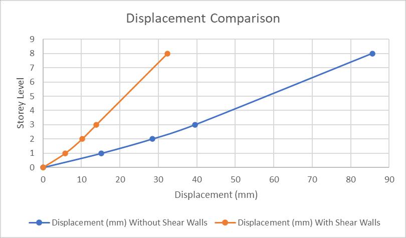
4.2 Lateral Displacement
Lateraldisplacementwasanalyzedforbothmodelstoassess theeffectivenessofshearwallsincontrollingthedeflection.
Table -2: DisplacementwithandwithoutShearWallswith respecttoStoreyLevel

International Research Journal of Engineering and Technology (IRJET) e-ISSN: 2395-0056
Volume: 11 Issue: 10 | Oct 2024 www.irjet.net p-ISSN: 2395-0072

Figure-3: Displacement Comparison Graph
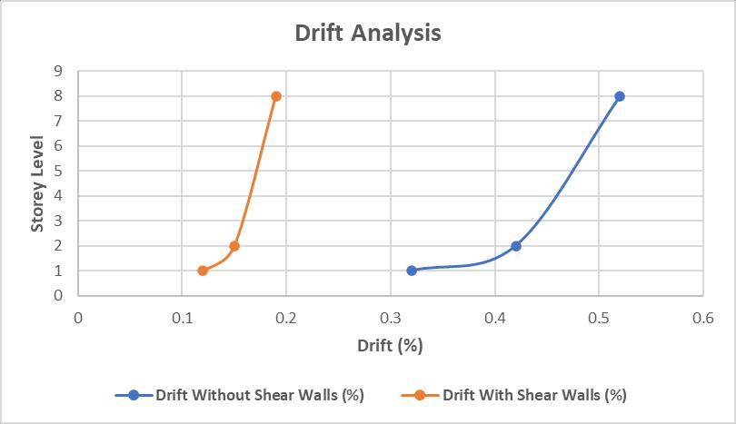
4.3 Drift Analysis
Theinter-storeydriftwascalculated,andtheresultsshow thatthestructurewithshearwallshassignificantlyreduced drift,wellwithinthepermissiblelimitsasperIS1893:2016.
Table -3: DriftwithandwithoutShearWallswithrespectto StoreyLevel
5.1 Columns and Beams
Columns: Columndimensionsof600mmx600mm were used throughout thestructure.Longitudinal reinforcement was designed considering IS 456:2000 requirements, with minimum steel percentageof1%andmaximumof4%.
Beams: Beamsofcross-section300mmx450mm weredesigned.Shearreinforcementwasprovided asperIS13920forearthquakeresistance.
5.2 Shear Walls
Shear Wall Dimensions: 200mmthickshearwalls wereprovidedalongtheperimeter.
Reinforcement: Horizontal and vertical reinforcement with 12 mm diameter bars at 150 mmc/cwasprovided.
6.1 Risk with and without Shear Walls
The risk assessment of the building was carried out considering the vulnerability of structures during seismic events.
Without Shear Walls: Thestructurewithoutshear wallsexhibitedhigherdeflections andlargerbase shear, increasing the risk of failure under seismic loads.
With Shear Walls: Thestructurewithshearwalls performed better, showing reduced displacement anddrift,thusreducingtherisk.

Figure-4: Drift Analysis Comparison Graph
6.2 Graphical Representation
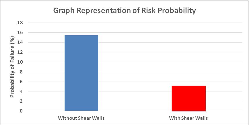
Risk Probability: A risk probability of structural failurewasevaluatedusingfragilitycurvesforboth models.
Table -4: ProbabilityofFailurewithandwithoutShear Walls
Model
ProbabilityofFailure(%)
WithoutShearWalls 15.4
WithShearWalls 5.2

International Research Journal of Engineering and Technology (IRJET) e-ISSN: 2395-0056
Volume: 11 Issue: 10 | Oct 2024 www.irjet.net p-ISSN: 2395-0072

Figure-5: Risk Probability Comparison Bar Chart
7. Conclusions
ThedesignandanalysisofaG+8RCCframedstructurewith and without shear walls reveal significant differences in seismicperformance.Theinclusionofshearwallsreduces lateral displacement, drift, and overall risk of structural failure.Keyconclusionsare:
1. Base Shear:Thepresenceofshearwallsincreases the base shear, indicating improved resistance to lateralforces.
2. Displacement and Drift:Shearwallssignificantly reducelateraldisplacementandinter-storeydrift.
3. Risk Reduction: The probability of failure is reduced by incorporating shear walls, leading to enhancedstructuralsafety.
7.1 Recommendations
Shearwallsarerecommendedforstructuresinhigh seismic zonestoimprovestabilityandreducethe riskoffailure.
Further studies can be conducted using other grades of concrete and different soil types to generalizethefindings.
8. References
IS 456:2000, "Code of Practice for Plain and ReinforcedConcrete,"BureauofIndianStandards.
IS 1893 (Part 1):2016, "Criteria for Earthquake Resistant Design of Structures," Bureau of Indian Standards.
STAADProUserManual,BentleySystems.
IS 13920:2016, "Ductile Design and Detailing of Reinforced Concrete Structures Subjected to SeismicForces,"BureauofIndianStandards
9. Biographies


SuhailRaza
Diploma in Civil Engineering from Jamia Millia Islamia, NewDelhi,India,inthebatch of2015-2018.
Bachelor of Technology in Civil Engineering from Lingaya’s Vidyapeeth Faridabad,India,inthebatch of2022-2025.
PrashantVashisht
AssistantProfessor,Lingaya’s Vidyapeeth,Faridabad,India