
International Research Journal of Engineering and Technology (IRJET) e-ISSN:2395-0056
Volume: 11 Issue: 10 | Oct 2024 www.irjet.net
p-ISSN:2395-0072

International Research Journal of Engineering and Technology (IRJET) e-ISSN:2395-0056
Volume: 11 Issue: 10 | Oct 2024 www.irjet.net
p-ISSN:2395-0072
Barri Sravani1 , Prof.T.R.Jyothsna2
1Electrical Engineering, PG scholar, Andhra University, kakaninagar, Visakhapatnam, India
2Electrical Engineering, Professor, Andhra University, Maddilapalem, Visakhapatnam, India
The Doubly-Fed Induction Generator (DFIG) plays a critical part in present day wind vitality frameworks due to its adaptability in variable-speed applications, tall proficiency, and capability to work beneath fluctuating wind conditions. In the show situation, DFIGs are broadly utilized in wind turbines since they permit autonomous control of dynamic and receptive control, upgrading framework steadiness and vitality productivity. The variable-speed operation empowered by the rotor-side converter too makes a difference moderate mechanical stresses on the turbine, progressing generally framework reliability.
The Proportional-Integral (PI) control methodology for DFIGs, advertising a few focal points such as effortlessness, ease of usage, and vigorous execution beneath different working conditions. By controlling both stator and rotor-side voltages and streams, PI controllers proficiently oversee dynamic and receptive control stream, guaranteeing smooth network integration. The PI control approach gives steady energetic reaction, diminished motions, and improved framework execution, making it a well-known choice for both grid-connected and standalone DFIG applications.
This investigates rotor and stator current flow for torque and control, giving experiences into how successful control can optimize control yield and make strides framework steadiness. By considering these cases, the proposed control strategy illustrates made strides execution in controlling electrical amounts, accomplishing craved control stream, and minimizing unsettling influences in real-world operational scenarios.
Keywords - Small Signal Stability, DFIG, WT, RSC, GSC
Energy Conversion Systems(WECS):
Overview of Wind Energy Conversion Systems(WECS):
The system to convert the kinetic energy present in the wind to useful form of energy is known as Wind Energy Conversion System(WECS). In the history, the power in the wind was exercised to give useful mechanical power but in ultramodern world WECSis substantiallyconcentrated onconversionofenergyto electrical form.Thereareastronomically two types of WECS – vertical axis type and perpendicular axis type. Presently, vertical axis wind turbines are the most commerciallyfeasibleforbulkpowergenerationoperations.
A WECS can be distinctly divided into three different corridor aerodynamic system, mechanical system and the electricalsystemasshowninfigurebelow.
1)Aerodynamicsystem TheaerodynamicsoftheWECSsystemconsistsofwindturbineblades,turbinecapitalsand turbinerotor.Thekineticenergyisconvertedintothemechanicalenergyinthissystem.likewise,utmostultramodernwind turbinerotorsareequippedwithpitchservos,insidethemecca,thatrotatethebladesalongtheirlongitudinalaxestocontrol theaerodynamicbehavioroftheblades.
2)Mechanicalsystem Themechanicalenergyattainedfromthekineticenergyisreusedinthissystem.Itconsistsof thedrive-trainmadeofalow-speedshaftcoupledtotherotatingmecca,agearbox(speedmultiplier)thatincreasesthelow
International Research Journal of Engineering and Technology (IRJET) e-ISSN:2395-0056
Volume: 11 Issue: 10 | Oct 2024 www.irjet.net p-ISSN:2395-0072
rotationalspeedoftherotortoaadvancedspeedsuitablefortheelectriccreator,andahigh-speedshaftdrivingtheelectric creator.
3) Electrical system The mechanical energy is converted into the electrical energy in this part. It consists of the electricalcreator,powertransformers,gridconnection.
Model for power system studies:
For power system studies it is common to represent generators with a simple equivalent model where by the machine is representedasa voltagesourcebehindtransientimpedance,FortheDFIG,thecurrentinjectedto thegridisthesumofthe statorcurrentIsandgrid-sideconverterac-currentIGSC.
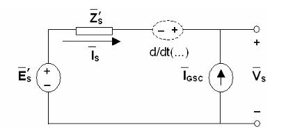
Figure 2.1: Generators as voltage source behind transient impedance
Thedrivetrainmodelisobtainedbyrearrangingequations()asfollows,
International Research Journal of Engineering and Technology (IRJET) e-ISSN:2395-0056
Volume: 11 Issue: 10 | Oct 2024 www.irjet.net p-ISSN:2395-0072
TheDFIGstatorandrotorequivalentcircuitintermsofcomplexvariables,therotorvoltageVr isacontrolledvoltagesource, whichisdeterminedbytherotor-sideconverter.TheconvertercurrentIGSCisacontrolledcurrentsource,whichis determinedbythegrid-sideconvertercontrols.
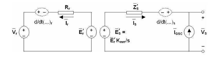
Figure 2.2: In detail Generators as voltage source behind transient impedance
III. IMPLEMENTATION OF PI CONTROLLER:
RSC controls the stator reactive power and electromagnetic torque that is generated by DFIG machine. PI controller is implementedinfigurebelow.
Rotor side converter control:
At the RSC side, the electromagnetic torque is more sensitive to and stator reactive power is more sensitive to idr. As shown in (31.) and (3.2), the outer loop consists torque controller where the actual value of is compared with . The errorisreducedtozerobytheuseoftorquecontroller.Outputfromthetorquecontrollerisreferencerotorcurrent( ). Now, is compared with and makes the error is reduced to zero by the use of current controller. Output from this currentcontrollerisq-axisvoltage( )thatmustbegeneratedtoRSC.
Theimplementationofpicontrollerforelectromagnetictorquecontrolisasfollows:
Figure 3.1: PI control loop for electromagnetic torque at RSC side
Thedynamicequationsofpicontrollerimplementedfortorquecontrollerareasfollows:
International Research Journal of Engineering and Technology (IRJET) e-ISSN:2395-0056
Volume: 11 Issue: 10 | Oct 2024 www.irjet.net
p-ISSN:2395-0072
Asforthereactivepowerisconcerned( )iscomparedwiththereferencevalue( ),errorisreducedtozerobyintegral controlleraction.Outputfromtheoutercontrolloopis .Now, iscomparedwith andmakestheerrorisreduced tozero bytheuseofcurrentcontroller. Outputfrom thiscurrentcontrolleris d-axisvoltage( )thatmustbegenerated to RSC.
Figure 3.2: PI control loop for stator reactive power at RSC side
Thedynamicequationsofpicontrollerforstatorreactivepowerareasfollows: (3.5) (3.6) (3.7) (3.8)
Theoutputfromthecurrentregulator,dq-axesvoltageshouldbetransferredintoABCframe.ForthePWMgenerationofthe RSC,thesecontrolvoltagesareused.
Asexplainedabove,theGSCanddc-linkdynamicsarenotconsideredinthepresentwork. Thedc-voltageisassumedconstantandtheGSCisrepresentedasacurrentsource.ItisalsoassumedthattheGSCisoperated at unity power factor. Since the GSC controls are done instantaneously, the grid-side converter ac-current is such that the activepowerinjectedtothemainsmatchesthatoftherotor-sideconverteratunitypowerfactor,i.e.:
IGSC = IGSCref (3.9) sothat 1) PGSC = Pr (3.10) 2) QGSC = 0 (3.11)
Thedc-linkvoltageerrorisusedtomeasuretheimbalance.Hencebyassuminginstantaneousrotoractivepowertransfer,the dc-linkvoltageisconstantandnodynamicalmodelisrequiredforthedc-linkcapacitor.Theroleofthedc-linkcapacitoristo actasa voltagesourcetotheconverters.Fordriveapplicationsusinga dioderectifierontherotor-side,thedynamicsofthe dc-link components may not be ignored because of the dc energy storage mechanism, bulkier dc-components, and lesser controlcapability.Forback-to-backconvertershowever,anadequatecontroleliminatestheneedofstorageinthedc-linkand ensuresapracticallyconstantdc-voltage. Whenthedc-linkdynamicsareneglected,themodeloftheGSCissimply:
PGSC = Pr (3.12)
QGSC = Qtot (3.13) where definesthereactive powersharing betweenstatorandGSC.Forminimumconverter rating,asassumed inthistext, nosharingisdoneand = 0, QGSC = 0, Qs = (1- )Qtot = Qtot.Theinjectedcurrentgrid-sideconvertercurrentistherefore GSC = (PGSC +jQGSC) / = Pr / .
open loop states ( , ):
The 7x7 matrix constructed represents the open-loop state-space model of a doubly-fed induction generator (DFIG) connected to a wind turbine. The states in this system involve both the electrical dynamics of the DFIG and the mechanical dynamicsofthewindturbine.
International Research Journal of Engineering and Technology (IRJET) e-ISSN:2395-0056
Volume: 11 Issue: 10 | Oct 2024 www.irjet.net
Closed loop states ( , ):
Thissystemconsistsof11states(11*11matrix)equationsderivedfromadynamicmodelofadoubly-fedinductiongenerator (DFIG)-basedwindturbinesystem.ThesystemintegratesthedynamicsoftheDFIGelectricalmachine,thewindturbine,and controllers.
The system involves three sets of equations:
1. DFIG Electrical Equations (States1-4: ):
Governed by the stator and rotor voltage equations in the q and d axes. The dynamics depend on stator/rotor inductances, resistance,mutualcoupling,androtorspeed.
2. Turbine and Mechanical Equations (States5-7: ):
These equations come from the mechanical torque balance, including wind power, rotor dynamics, and torsional shaft dynamics.Thedynamicsalsoconsidergearboxratiosandturbineinertia.
3. Control Equations (States8-11: ):
PIcontrollersareusedtoregulatethestatorcurrents,torque,andvoltage.Thecontrolsignalsadjustthegenerator'selectrical dynamicsbasedonthedesiredreferencevalues.
Eigenvalues: The eigenvalues of the matrix provide insight into the stability and dynamic response of the system. If all eigenvalueshavenegativerealparts,thesystemisstable.Thevaluesindicatehowfastthesystem'sstatesdecayoroscillate overtime.
ROTOR Q-AXIS VOLTAGE ( ) and ROTOR D-AXIS VOLTAGE ( ):
2. (Stator d-axis current)
International Research Journal of Engineering and Technology (IRJET) e-ISSN:2395-0056
Volume: 11 Issue: 10 | Oct 2024 www.irjet.net p-ISSN:2395-0072
( ) Stator q-axis transient voltage ( ) ( ) ( ( )) ( ) (4.5) ( ) ( ) ( ) ( ) ( ) (4.6)
(Stator d-axis transient voltage) ( ) ( ) ( ( )) ( ) (4.7) ( ) ( ) (
( ) ( ) (4.8)
(Rotorspeed) ( ) ( ) ( ) ( ) ( ) ( )
) (4.9)
(Turbine speed)
( ) ( ) ( ) (4.10)
(Torsional twist angle)
( ) ( ) (4.11)
CONTROLLEREQUATIONS:
(Control signal for stator q-axis current) (4.12)
( ) ( ) ( ) ( ) (4..13)
(Control signal for stator d-axis current) (4.14) ( ) ( ) ( ) (4.15)
International Research Journal of Engineering and Technology (IRJET) e-ISSN:2395-0056
Volume: 11 Issue: 10 | Oct 2024 www.irjet.net
(Control signal for electromagnetic torque)
( ) ( ) ( ) ( ) (4.16)
Control signal for stator voltage (q-axis)
( ) ( ) (4.17)
OPEN LOOP TABULATED RESULTS:
Table4.1:Basecaseeigenvaluesofopen-loopDFIG
Operatingpoint: Vs =1, r =1,
-16.15±j313.30
-10.01±j63.67
-0.49±j3.33
-17.40
HF,MF,LF=high,medium,lowfrequency,NO=non-oscillating.
Case 1: Sensitivity to operating point
p-ISSN:2395-0072
SincetheDFIGmayoperateatlargeslipwithdifferentlevelsofactiveandreactivepower output,itisimportanttostudyhow itsdynamicbehaviourchangeswiththeseconditions.
i. Rotor speed and active power
Table4.2showstheopen-loopDFIGeigenvaluesforthreeparticularoperatingpoints.Asobservedabove,therotorspeedhas significanteffectonalltheeigenvalues,exceptforthehighfrequencymode.Atnon-synchronousspeed(sub-andsuper-),the electricalandmechanicaldynamicstendtobedecoupled.
Table4.2:Effectofrotorspeedonopen-loopDFIGeigenvalues
r =0.70pu, fosc
-16.29±j312.91 49.80 .052
-13.18±j114.37 18.06 .119
-5.24±j7.70 1.27 .524 -1.24 0 1
r =1pu, fosc
-16.15±j313.30 49.86 .052
-10.01±j63.67 10.13 .155
-0.49±j3.33 0.53 .138
-17.40 0 1
r =1.29pu, fosc
-16.29±j312.91 49.90 .051
-13.18±j114.37 17.55 .151
-5.24±j7.70 1.48 .243
-1.24 0 1
8.315
International Research Journal of Engineering and Technology (IRJET) e-ISSN:2395-0056
Volume: 11 Issue: 10 | Oct 2024 www.irjet.net p-ISSN:2395-0072
Inthissubsectiontheeffectofmachineinductances(Lss, Lrr and Lm),resistances(Rs and Rr)andmechanicalparameters(Hg, Ht and k)ontheeigenvaluesoftheopen-loopDFIGareobserved.Theseparametersvarywiththesizeofthemachine,thedesign, the materials used, and the working conditions (e.g. higher temperature). The range of parameter values may be large. It is thereforeworthwhiletoexaminehowthedynamicsareaffectedandwhethersomeparticularvaluesleadtoinstability.In this subsection,alleigenvaluesareobtainedforthebasecaseoperatingpoint,i.e.nominalterminalvoltageandsynchronousrotor speed(Vs =1pu, wr =1pu).
Themachineinductanceshavesignificanteffectonthestabilityoftheopen-loopDFIG.Forsomevalues,theopen-loopDFIGat zeroslipisunstable.Forthediscussion,itisusefultodefinetheratioofstatorselftomutualinductance ass = Lss / Lm ,theratio of rotor self to mutual inductance arr = Lrr / Lm, and the ‘transient stator inductance’ ( ) Table4.3showstheeigenvaluesoftheopen-loopDFIGatzeroslipfordifferentratios ass and arr withmutualinductance Lm =4 pu.
The machine is stable (all eigenvalues with negative real part) for L’s 0.01 . Alternatively, a more restrictive stability condition is that both ass 1 i.e. both Lss Lm and Lrr Lm , which means that leakage inductances are positive as explained below. When the magnitude of L’s is small i.e. when assarr 1(Lss Lm and Lrr Lm ) the eigenvalue sensitivity is largerandthereismorecouplingbetweenthemodes.
Table4.3:Effectofstatorandrotorinductancesonthemodesoftheopen-loop DFIGatzeroslip ass = Lss / Lm,, arr = Lrr / Lm ,L
Theparameter Ls mustbedifferentfromzeroinorderfor iqs and ids tobestatevariables(if L’s =0,thevariable iqs and ids are algebraic variables i.e. there is no stator transients). When L’s 0, the first two diagonal entries of the state matrix are Asys(1,1) = Asys(2,2) = . The diagonal elements of the state matrix are the centers of the Gershgorin disks which containtheeigenvaluesofthematrix.Hence forpositive L’s,thecentersofthe first twoGershgorindisks,arein thelefthalf plane.For negative L’s,the disk centers are in the right halfplane.As L’s isinthe denominator, thedisplacementin thedisk centersandhencethesensitivityoftheeigenvaluelocationwithrespectto L’s islargerforsmallamplitudeof L’s.
In the above discussion, the effect of varying the ratios ass and arr for a given value of mutual inductance Lm was examined. Table4.4showstheeffectofvarying Lm withconstantratio ass =1.01and arr =1.015.Theeigenvaluesinwhichelectricalstate variablesparticipate( , , )aremostlyaffected.Forallmodes,whenLmdecreases,therealpartmagnitudeincreases whiletheimaginarypartmagnitudechangesalsobuttoalesserextent.Since Lm isinverselyrelatedtotheairgaplength,this meansthatforlargerairgapmachine(smaller Lm),timeconstantsdecreaseanddampingratiosincrease.
International Research Journal of Engineering and Technology (IRJET) e-ISSN:2395-0056
Volume: 11 Issue: 10 | Oct 2024 www.irjet.net p-ISSN:2395-0072
Table4.4:Effectofmutualinductanceonthemodesoftheopen-loopDFIGatzeroslip Lmin[pu],ass=1.01,arr=1.015,L’s =Lm(ass-1/arr)
m L’s
1
ii. Resistances
Varying the stator and rotor resistance while keeping all other parameters constant causes noticeable displacement in eigenvaluesandchangeinparticipationfactors.Forthediscussion,theratiooftherotortostatorresistanceisdefinedas ar = Rr/Rs.Table4.5showstheeigenvaluesoftheopen-loopDFIGatzeroslipfordifferentvaluesofstatorresistance Rs with ar >1 and<1.
Table4.5:Effectofstatorandrotorresistanceonthemodesoftheopen-loopDFIGatzeroslip Rs in [pu], ar = Rr/Rs (Lm = 4 pu, ass = 1.01, arr = 1.015)
Rs ar Eigenvalues 0.0001 1.1
For the tested range of parameters, the system is stable. For larger resistance values, the real part magnitude of complex conjugate modes tends to be larger (i.e. oscillating modes are further away from the imaginary axis when resistances are larger). Hence more resistive machines have oscillatory dynamics with smaller time constants. For very resistive machines (Rs 0.1),therealmodeisthedominantmode(closesttotheimaginaryaxis)andthesystemisreferredtoasover-damped.
Formoreresistivemachines,theelectricalandmechanicaldynamicsaredecoupled,asshowninTable4.6,wherefor Rs =0.1, and areelectricalmodes, and aremechanicalmodes.
Table4.6:open-loopDFIGatzeroslipfordifferentresistances
Rs =0.1pu (ar =1.1, Lm =4pu, ass =1.01, arr = 1.015)
-616.63±j150.39
-40.90±j163.46
-7.9±j7.53 -1.39
Rs =0.0001pu (ar =1.1, Lm =4pu, ass =1.01, arr = 1.015)
-0.32±j314.15
-2.13±j63.18 -0.25±j1.05 -0.34
International Research Journal of Engineering and Technology (IRJET) e-ISSN:2395-0056
Volume: 11 Issue: 10 | Oct 2024 www.irjet.net p-ISSN:2395-0072
iii. Mechanical parameters
Table4.7showstheeffectofvaryinginertiasandstiffnessontheopen-loopDFIGeigenvalues.Asexpected,heaviermachines (large Ht and Hg)presentoscillationswithlowerfrequencies,anddrivetrainsthatarestiffer(smallergearboxratioi.e.larger k)haveoscillationswithhigherfrequencies.
Table4.7:Effectofdrivetrainparametersonthemodesoftheopen-loopDFIGatzeroslip Ht in[s], Hg =0.1Ht , k = 0.3pu
Ht (fosc[HZ], ) (fosc[HZ], )
12 -15.92±j313.3 -8.91±j36.06 (5.75,.239) -0.32±j1.92 (0.31,.168) -17.39
8 -15.97±j313.3 -9.19±j44.59 (7.11,.201) -0.36±j2.35 (0.37,.155) -17.40
4 -16.15±j313.3 -10.00±j63.66 (10.2,.155) -0.49±j3.33 (0.53,.146) -17.40
2 -16.51±j313.2 -11.61±j90.42 (14.4,.123) -0.73±j4.70 (0.75,.155) -17.40 1 -17.36±j313.2 -14.72±j128.0 (20.4,.114)
k in[pu], Ht =4s,Hg=0.1Ht
For the tested range of parameters, the machine dynamics remain stable. The electrical modes (high frequency and nonoscillatingmodes)arenotsignificantlysensitivetomechanicalparameters.
(f
.3 -16.15±j313.30 -10.00±j63.66 (10.2,.155) -0.49±j3.33 (0.53,.146) -17.40
.03 -16.15±j313.30 -10.21±j62.85 (10.0,.160) -0.27±j1.04 (0.17,.260) -17.40
.003 -16.15±j313.30 -10.24±j62.77 (10.0.160) -0.25±j0.22 (0.04,.758) -17.40
CLOSED LOOP TABULATED RESULTS:
Case1:Closed-loopDFIGeigenvalues
Tofacilitatethediscussion,thetypicaleigenvaluesofaclosed-loopDFIGwithproperlytunedcontrolsarefirstpresentedand comparedwiththoseoftheopen-loopcase.ThetuningmethodoftherotorsideconverterPIcontrollersisdiscussedindetail subsequently.
Table 4.8 shows the typical eigenvalues of a well-tuned closed-loop DFIG. Details on the determination of the control parametersaregiveninthenextsubsections.Thefollowingeigenvaluescanbedistinguished:
Statormodes( )
Rotorfluxmodes( )
Turbine modes( )
Controllermodes( Φiq , Φid , ΦTe , Φqs )
TABLE4.8:EigenvaluesoftheDFIGwithclosedcontrols q-axisgains:KTe =-1.5 TTe=0.250 Kiq =-1 Tiq =0.0250 d-axisgains:KQs =1 TQs =0.50 Kid =-0.5 Tid =0.050
Dominantstates
International Research Journal of Engineering and Technology (IRJET) e-ISSN:2395-0056
Volume: 11 Issue: 10 | Oct 2024 www.irjet.net
p-ISSN:2395-0072
Thestatormodesarerealandhavelargemagnitude.Thelocationofthestatoreigen valuesdependonmachineparameters, operatingpointandindeedcontrolparameters.Asexplainedlater,theyareeitherfarintheLHPorfarintheRHP.Thecontrol parameters can be chosen so that the stator modes are placed at some desired location. Limit values for the controller proportional gains can be determined to ensure that the stator modes are in the LHP (see next subsection). It is noted that largemagnitudesforthestatoreigenvaluesarenotaproblem(theproblemisapositivesignasitmeansinstability).Infact, large negative real part is desirable since in such case the eigenvalue can be considered to be at (relatively to the other eigenvalues)sothatstatortransientscanbeneglectedi.e.sothatstatorvariablescanbeapproximated asalgebraicvariables insteadofstatevariables(differentialvariables).
The rotor-flux mode is a high-frequency oscillating mode (40 55 Hz). It is sensitive to the model order (neglecting stator transientschangesthelocationofthismode)andcontrollerparameters.Ifthecontrollersarenottunedproperly,thismode isintheRHP.Limitvaluesfortheproportionalgainscanalsobedeterminedtoensurethattherotorfluxisstable(seenext subsection).Itisseenthatthehighfrequencymode(50Hz) isduetotherotorelectrical dynamics.Thisisincontrastwith the familiar result for the synchronous generator, squirrel-cage induction generator and open-loop DFIG where the 50 Hz mode is associated with stator dynamics. For the closed-loop DFIG, neglecting stator transients does not remove the 50 Hz mode,thoughitincreasesslightlyitsdamping.
Thecontrollermodesmayberealorhighlydampedcomplex-conjugatesdependingonthecontrolparameters.Theymayalso becoupledwiththegeneratorordrivetraindynamicsdependingonthecontrolparameters.
From the observations, the closed-loop system differs from the open-loop configuration in several aspects. Apart from introducing controller modes and changing the coupling of the machine dynamics (no electro-mechanical mode for the closed-loopsystem),animportantconsequenceoftheconvertercontrollersisthatstatordynamicsareassociatedwithlarge real eigenvalues while the 50 Hz mode is associated with rotor electrical dynamics. As rotor electrical dynamics are not significantly coupled with the other dynamics, both stator and rotor electrical dynamics should be neglected if the point of interest is in low frequency oscillations as for power system stability studies (neglecting stator transients only does not removethe50Hzoscillations).
ForeachPI controller), the parametersKandT (proportional gainsand integral times)have to be selected for stabilityand desiredperformance.Root-lociplotsshowthatstabilityoftheclosed-loopDFIG ismainlydecided bytheproportional gains (P-gains),whiletheintegraltimes(I-times)influencemainlythespeedofintegralaction.Inthissection,theparticularissues relating to stability are examined, hence the discussion focusses on the P-gains. The effect of the I-times is reviewed in the nextsection.
Below,thereareDFIGmodelsareconsidered:
Full-ordermodel(FOM)
5thordermodel(5thOM):statortransientsneglected
3rdordermodel(3rdOM):statorandrotorelectricaltransientsneglected
WeconsideredtheFull-ordermodel(FOM)inexperimentalthroughcontroller.
In the full-order model, all electrical dynamics (stator and rotor) change with a finite speed, and the DFIG has seven state variables (iqs, ids, eqs, eds, ). In the 5th order model, the stator variables are considered as algebraic, in other wordstheyareassumedtochangeinstantaneously;theDFIGhasfivestatevariables(eqs,eds, ).Inthe3rdorder model,allelectricalvariablesareconsideredasalgebraic,andtheDFIGhasthreestatevariablesrepresentingthemechanical dynamics ( ). Since there are four controller states ( Φiq , Φid , ΦTe , Φqs), the model order of the closed-loop DFIG(numberofDFIGstates+numberofcontrollerstates)is11,9and7fortheFOM,5th OMand3rd OMrespectively.
4.5.2InappropriatetuningwithsimplifiedDFIGmodel
International Research Journal of Engineering and Technology (IRJET) e-ISSN:2395-0056
Volume: 11 Issue: 10 | Oct 2024 www.irjet.net p-ISSN:2395-0072
OneparticularityoftheDFIGisthatwhentuningthecontrollerswiththe5th or3rd OM,onemayobtainasetofPI-gainsgiving stableresultsforthereducedordermodels,butunstableforthefullordermodel.
4.9ExampleofinadequatePIgainsandcorrespondingeigenvalues q-axisgains:KTe =-1.5 TTe=0.250 Kiq =-1 Tiq =0.0250 d-axisgains:KQs =1 TQs =0.50 Kid =-0.5 Tid =0.050
Dominantstates
In Table 4.9, the DFIG is stable if stator or both stator and rotor electrical transients are neglected . However, the DFIG is unstable if both stator and rotor electrical transients are considered (FOM) in which case the rear two eigen values in the RHP.Inotherwords,ifstatorvariableschangeinstantaneously,theDFIGisstable;ifhowever,statordynamicshaveasmall but non-zero time constant (which is more likely to Both case in the real system), the DFIG is unstable. This is undesirable asstabilityissensitivetomodelorderandonlyguaranteedintheidealcasewherestatororbothstators.
4.5.3Statormode’slocation:LimitvalueoftheP-gains
The location of the stator modes can be evaluated analytically by applying Gershgorin theorem [130] on the state matrix of theclosed-loopgridconnectedDFIG.GershgorintheoremstatesthattheeigenvaluesofamatrixAarelocatedintheunionof the disks in the complex plane which have as centre the diagonal elements of A and as radius the sum of the off-diagonal elements (either row-wise or column-wise) [130]. Hence if all diagonal elements have negative real part, all disks are centeredintheLHPandtheeigenvaluesaremorelikelytobeintheLHP.
For the closed-loop DFIG full order model, the diagonal elements of the state matrix corresponding to the differential equationsofthestatorstates(iqs and ids)are: ( ( ) [ ] )( ) (4.18) ( ( * + ) * + )( ) (4.19)
Where / , and depend on the external network. Obtaining an analytical expression for these termsisnotreadilyfeasible.Inafirststeptheycanbeignored,whichisthesameasassumingconstantterminalvoltage(i.e. the DFIG is connected to an infinitely strong system). The effect of non-constant terminal voltage can be checked subsequentlywithnumericalcomputationoftheeigenvaluesandtimedomainsimulations.Hence: ( )( ) (4.20) ( )( ) (4.21)
Itis seen that a11 and a22 depend on the operating point ( , ),the machine parameters(R1, Kmrr, L’s), and the P-gains (Kiq, Kid, KTe, KQs).ThedynamicsoftheDFIGaresuchthatthestatoreigenvaluesarerelativelycloserto a11 and a22 thantothe otherdiagonalelementsofthestatematrix.InGershgorinframework,thisisbecauseatransformationcanbeappliedtothe statematrixsothatthediskscenteredat a11 and a22 aredisconnectedfromtheremainingdisks
International Research Journal of Engineering and Technology (IRJET) e-ISSN:2395-0056
Volume: 11 Issue: 10 | Oct 2024 www.irjet.net p-ISSN:2395-0072
Inotherwords,onecanobtainasetofP-gainsforsomedesiredlocationof a11 and a22,i.e.onecanplacethestatormodesin somedesiredregionofthelefthalfplanearound a11 and a22 bychoosingtheP-gainsappropriately.E.g.forthe q-axisstator modetobeintheLHParound-T1 whereT1 isrealpositive,i.e.forthecondition a11 -T1 tobesatisfied,thethresholdvalue (minimumormaximum)oftheproportionalgain KTe canbeobtainedusing(4.118)as:
If and 0
If and 0
If and 0 (4.22)
If and 0
Where,
( ( ) )( ) (4.23)
Similarly,forthed-axisstatormodetobeintheLHParound-T2whereT2isrealpositive,i.e.forthecondition a22 T2 tobe satisfied,onecanobtainthethresholdvalueoftheproportionalgain KQs using(4.119)as: If If (4.24)
Where
( ( ) )( ) (4.25)
Equations(4.120)-(4.123)giverestrictionsontheouterloopP-gainsforsome T1 and T2 asfunctionofinnerloopP-gainsand operatingpoint.Astheintegraltimeofthecurrentcontrollersisintheorderofmilliseconds,aconsistentchoicefor T1 and T2 is T1 = T2 =10000whichgivesatimeconstantforthestatormodesintheorderof1/10000=0.1msi.e.tentimesfasterthan thecurrentcontrollerintegralaction(statortransientsshouldbefastersothattheycanbeneglected).
4.5.4 Robustnessverification:
The above analysis describes the dynamics around a particular operating point for some machine parameters and small disturbances.Inthissection,theeffectofchangingpara metersandconditionsontheeigenvaluesoftheclosed-loopDFIGis examined.
i. Robustness to operating point
Table4.10:Effectofrotorspeedontheclosed-loopDFIGModes
1.1
Fortable4.10differentrotorspeeds,theonlynoticeablevariationisinthemechanicalturbine mode, which is closer to the imaginary axis for synchronous and super-synchronous speed but remains stable. This means thatfor wr therotationalspeedtakeslongertoreachanewsteadystatevalue.
International Research Journal of Engineering and Technology (IRJET) e-ISSN:2395-0056
Volume: 11 Issue: 10 | Oct 2024 www.irjet.net p-ISSN:2395-0072
Table 4.11 show the effect of the terminal voltage and reactive power level on the closed-loop DFIG modes. Again, the dynamicalcharacteristicsofthesystemarepreservedoverthewiderangeoftestedconditions.
Table4.11:Effectofterminalvoltageonclosed-loopDFIGmodes
ii. Robustness to machine parameters
Table4.12and4.13givetheclosed-loopDFIGeigenvalueswiththegainsfordifferentmachineinductancesandresistances. 4.12:Effectofinductancesontheclosed-loopDFIGmodes
ControlparametersofTable4.12areused;Lss=1.01Lm;Lrr=1.005Lss
It is seen that for the wide range of values considered, the dynamical characteristics of the system are preserved. The electrical modes are sensitive to the variation of inductances and resistances. For high inductances, the magnitude of the stator modes are reduced but they remain far from the current controller modes in the LHP. For different resistances, the DFIGmodesarevirtuallyunchangedwhenresistancesaresmall.Inveryresistivemachine,the50Hzmode(rotorfluxmode) hasalowerdampingratio.Retuningofthecontrollersmayberequiredtokeepthedampingratioatanacceptablelevel.
International Research Journal of Engineering and Technology (IRJET) e-ISSN:2395-0056
Volume: 11 Issue: 10 | Oct 2024 www.irjet.net p-ISSN:2395-0072
Table4.13:Effectofresistancesontheclosed-loopDFIGmodes
ControlparametersofTable5.5areused;Rr=1.1Rs
Table 4.14 gives the closed-loop DFIG modes for different inertias. The mechanical modes are sensitive to the variation of inertias. For heavier machines, the mechanical dynamics are slower (smaller real part magnitude) as expected but remain stable.
Table4.14:Effectofinertiasontheclosed-loopDFIGmodesControlparametersofTable5.5areused;Hg=0.1Ht
In this Work the wind driven DFIG model was been presented. Model equations were been derived and parameters data of eachcomponentwereprovided.Fortheturbine,dynamic models(aerodynamicsoftheairflowaroundtheturbine)areused forturbinedesignorspecificsite-turbineevaluation.
Forpowersystemmodelstabilitystudies,wherethemechanicalinputpowerisobtainedfromthewindspeed,pitchangleand rotorspeed.Aprocedurehasbeengivenforconsistentdimensioncalculationwhenusingnumericalapproximations withCp curve. In such case, the drive train does not behave as a single equivalent rotating mass. In addition to evaluate the control performanceaccurately,itisimportanttoconsiderthechangeinrotorspeedasrealisticallyaspossible.Hencethetwomassmodelisused.
© 2024, IRJET | Impact Factor value: 8.315 | ISO 9001:2008 Certified Journal | Page624
International Research Journal of Engineering and Technology (IRJET) e-ISSN:2395-0056
Volume: 11 Issue: 10 | Oct 2024 www.irjet.net p-ISSN:2395-0072
For the induction generator, the derivation of the model equations has been presented to define unambiguously all parameters, variables and conventions used in the present work. For power system model studies, the DFIG can be represented as a voltage source (proportional to rotor flux) behind transient impedance, with a shunt controlled current sourceattheterminalrepresentingthecurrentfromthegrid-sideconverter.Detailedexplanationfortheperunitconversion hadbeendoneinthisworkandchoiceofthebasevalueshavebeengiven.
Fortheac-dc-acconverter,thegridsideconvertercontrolsareassumedasideali.e. thedc-voltageisconstant(hencedc-link dynamicsareignored)andtheGSCtransferstherotoractivepowerinstantaneouslytoorfromthegrid.Itisalsoassumedthat the GSC is operated at unity power factor. The RSC on the other hand is modelled as a controlled voltage source. The rotor voltagesetpointsaredeterminedbytwoloopsofPI-controllersincascaderegulatingtheelectricaltorqueandreactivepower. Switchingtransientswereignoredandrotorvoltagesareinstantaneouslyequaltotheirsetpoints.
[1] F. Mei, B.C. Pal, “Modal Analysis of a Grid Connected Doubly-Fed Induction Generator,” in Proc. of Power Electronics, MachinesandDrivesInt.Conf.,April2006,pp611-615.F.
[2]. Mei, B.C. Pal, “Modelling and dynamic behavior of wind generation as it re lates to power system control and dynamic performance,”inCigreTechnicalReportWorkingGroup601ofStudyCommitteeC4,CIGRE-WG-601.C4,Chaptercontribution, January2007.
[3]. F.Mei,B.C.Pal,“Modalanalysisofgridconnecteddoubly-fedinductiongenerators,”inIEEEtrans.onEnergyConversion, vol22,nb3,September2007,pp728-736.F.Mei,B.C.Pal,“OnthemodellingadequacyoftheDFIGinpower systemstability studies,”inIETJournalofRenewablePowerGeneration,vol2,nb3,September2008,pp181-190
[4]. Boldea,VariableSpeedGenerators.CRCPressTaylor&Francis,2006. BoldeaandA.Nasar,TheInductionMachine Handbook.CRCPress,2006.
[5]. W.Leonhard,ControlofElectricalDrives.Springer-Verlag,1985.
[6]. M.P.Kazmierkowski,R.Krishnan,andF.Blaabjerg,ControlinPowerElectronics:SelectedProblems.AcademicPress, 2002.
[7]. P.Vas,SensorlessVectorandDirectTorqueControl.OxfordUniversityPress,1998. R.H.Park,TwoReactionsTheoryof SynchronousMachines.AIEETransactions.Vol.48,pp.716–730,1928.