
International Research Journal of Engineering and Technology (IRJET) e-ISSN: 2395-0056
Volume: 11 Issue: 10 | Oct 2024 www.irjet.net p-ISSN: 2395-0072

International Research Journal of Engineering and Technology (IRJET) e-ISSN: 2395-0056
Volume: 11 Issue: 10 | Oct 2024 www.irjet.net p-ISSN: 2395-0072
Mohmed Rifat Sakharkar1, Roshni John2
1P.G Student (M.E Structural Engineering), Department of Civil Engineering, Saraswati college of Engineering, Kharghar, Navi Mumbai, India
2Associate Professor, Department of Civil Engineering, Saraswati college of Engineering, Kharghar, Navi Mumbai, India.
Abstract - A flat slab is a reinforced concrete slab which is directly rested on Columns without any beams, offering flexibility in design. It provides a spacious interior without obstructionfrombeams, makingit ideal for largeopenspaces. On the other hand, a flat slab with drops incorporates thicker areas, or drops, around the columns to enhance structural strength and distribute loads more efficiently. The primary objective of this investigation is to learn the valuable insights into the structural behaviour of two different flat slab types. This research endeavours to investigate the seismic performance of a multi-story residential building situated in seismic zone III having the re-entrant corners with U-shaped plan regularity, using response spectrum analysis in accordance with IS-1893:2016 standards. The study explores flat slab, and flat slab with drop. Parameters of interest include Story displacement, time period, base shear, and punching shear.
Keywords: Flat Slab, Flat Slabwith Drop, Re-entrant corners, Story Displacement, Time Period, Punching Shear.
1.INTRODUCTION
Thisdocumentistemplate.Weaskthatauthorsfollowsome simpleguidelines.Inessence,weaskyoutomakeyourpaper lookexactlylikethisdocument.Theeasiestwaytodothisis simplytodownloadthetemplate,andreplace(copy-paste) thecontentwithyourownmaterial.Numberthereference itemsconsecutivelyinsquarebrackets(e.g.[1]). However the authors name can be used along with the reference number in the running text. The order of reference in the runningtextshouldmatchwiththelistofreferencesatthe endofthepaper.
Thecurrentstudyinvolvestheexaminationofaframed structure,afive-storyflatslabandflatslabwithdropbuilding (G+5).Fortheinvestigation,dynamicseismicanalysis,itis considered that the building is located in Mumbai with SeismiczoneIIIandtheframesarefixedwithinamedium soilcontext.
Aesthetics,functionality,andstructuralefficiency.These slabsalsoprovideexcellentlightingconditions,astheyallow naturallighttopassthrough,contributingtoa well-litand airyinterior.Theirdesignprovidesacleanandopeninterior spacewhileensuringthatthebuildingisstableandsafe.
However,punchingshearinflatslabsisastructuralissue related to the transfer of shear forces at the edges of supportingcolumns.Topreventthecolumnsfrompuncturing throughflatslabs,structuralengineersemploydroppanels. Thesearealsoknownascolumncapitalsordropcaps.Drop panels involve thickening the slab directly around the column. By adding extra thickness to the slab in the immediate vicinity of the column, drop panels effectively dispersetheloadsfromthecolumnoveralargerareaofthe slab.
Re-entrantcornerirregularityexistswhendimensionsof projectionsinbothofthetwoperpendiculardirectionsina building'sfloorplanexceedthetotalplandimensionsofthat story of the building in the respective directions by more than15%.Thisdefinitioniscrucialinthecontextofseismic design, as it helps identify buildings with irregular configurationsthatmayhavedifferentseismicbehaviorand loaddistributionpatterns.Buildingswithre-entrantcorner irregularities require additional structural analysis and reinforcementtoensuretheirsafetyunderseismicforces,as specifiedbyIS1893:2016andrelevantbuildingcodes.
1) Conduct a comparative analysis of residential buildings with Flat Slab and Flat Slab with Drop Panelsundersameloadsandloadcombinations.
2) Assessandcomparethestructuralperformanceof buildingslocatedinseismiczoneIIIwithmedium soilconditionsusingResponseSpectrumAnalysis.
3) Evaluatetheresultsobtainedfromtheanalysisof Flat Slabs and Flat Slabs with Drop Panels with respecttorespectiveparametersmentionedbelow.
a) Storey-Displacement
International Research Journal of Engineering and Technology (IRJET) e-ISSN: 2395-0056
Volume: 11 Issue: 10 | Oct 2024 www.irjet.net p-ISSN: 2395-0072
b) PunchingShear
c) TimePeriod
The current study involves the examination of a framed structure, a five-story flat slab and flat slab with drop building (G+5). For the investigation, dynamic seismic analysis, it is considered that the building is located in Mumbai with Seismic zone III and the frames are fixed withinamediumsoilcontext
Table -1: MaterialProperties
GradeofConcrete M30
GradeofSteel Fe500
DensityofReinforcedConcrete 25(inkN/m³)
DensityofBrick 20(inkN/m³)
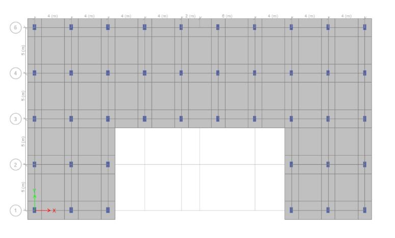
Table -2: BuildingParameter
BuildingType FramedStructure(G+5Stories)
StoryHeight 3meters
ColumnSize 350x600mm
SlabThickness 150mm
Table 3: DescriptionofModels
Models Description
1 FlatSlab
2 FlatSlabwithDrop
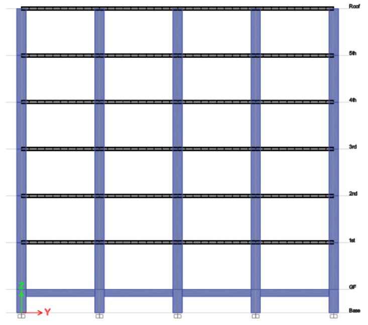
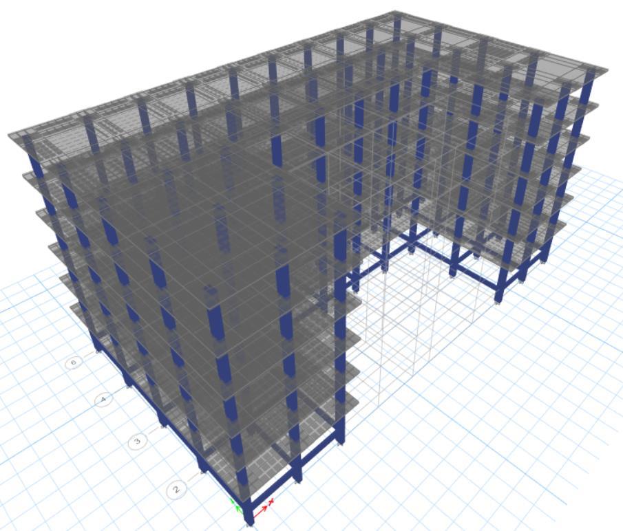
Table 4: SeismicParameters
SeismicZone III
ZoneFactor 0.16
ImportanceFactor 1
ResponseReduction 5
SoilType MediumSoil(TypeII)
TimePeriod(X) 0.2925sec
TimePeriod(Y)
sec Damping
Eccentricity
International Research Journal of Engineering and Technology (IRJET) e-ISSN: 2395-0056
Volume: 11 Issue: 10 | Oct 2024 www.irjet.net p-ISSN: 2395-0072
ThefollowingresultswereobtainedfromETABSsoftware usingtheResponsespectrumanalysisofmodelsasstatedin the problem statement above. The parameters like Storey Displacement,BaseShear,TimePeriod,andPunchingShear wereComputedforfurtherConclusions.
Storeydisplacementreferstothehorizontalmovementor deflection of a building's storey during an earthquake or otherlateralforces.It'sacriticalaspectinstructuraldesignto ensurethesafetyandstabilityofabuilding.
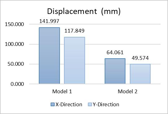
Chart -1:StoreyDisplacement
Incomparingbuildingmodelsforstructuralperformance, certain observations emerged. When Flat Slab Building (Model 1) was compared with the Flat Slab with Drop Building (Model 2), a notable decrease of 54.88% was observed.
4.2 Base Shear
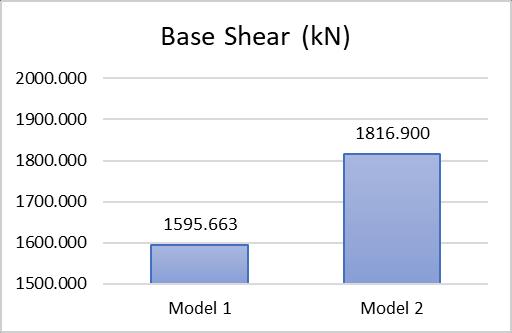
Chart -2:BaseShear
It represents the maximum horizontal force that a building'sfoundationmustwithstandduringanearthquake. Themagnitudeofthisforcedependsonfactorssuchasthe structure'sweight,height,andtheseismicconditionsofthe region. Codes and standards, like IS 1893:2016 in India, provideguidelinesforcalculatingbaseshear.
TheFlatSlabwithDropBuilding(Model2)experienceda notableincreaseof13.86%indisplacementcomparedtothe FlatSlabBuilding(Model1).
Timeperiodisafundamentalconceptthatrelatestohow quickly a building or structure sways back and forth after beingsubjectedtoaforce,likeanearthquake.Engineersuse the time period toassessa building's natural frequencyof vibration, which is crucial for ensuring that it doesn't resonate or oscillate excessively when faced with external forces.
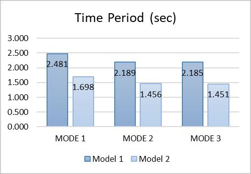
Chart -3:TimePeriod
4.4
Punching shear refers to thedownward force or stress that occurs around the columns, specifically at the slabcolumn connections. The Punching shear is calculated manuallybyreferringtheIS456:2000.Herearetheresults obtained for flat slab and flat slab with drop buildings respectively.
4.4.1
TotalFactoredload(Vu)=450kN
Nominalshearstress(τv)=Vu/bd=1.675N/mm2
Shearstrengthofconcrete=ks τc=1.36N/mm2
Therefore, τv > τc which states that the nominal shear stressexceedstheshearstrengthofconcreteHence,theslab isunsafeinpunchingshear.
International Research Journal of Engineering and Technology (IRJET) e-ISSN: 2395-0056
Volume: 11 Issue: 10 | Oct 2024 www.irjet.net p-ISSN: 2395-0072
Table 5: PunchingShear(FlatSlabBuilding)
LoadCalculation(FlatSlab)
Description Calculation
LoadfromSlab
Selfwt.ofSlab
FloorFinish+LiveLoad
TotalLoad(kN)
LoadduetoBrickwalls AreaofWall
kN/m2
kN/m2
kN
m2
kN TotalFactoredLoad(Vu)
kN
4.4.1 Calculations For Flab with Drop Building
TotalFactoredload(Vu)=500kN
Nominalshearstress(τv)=Vu/bd=0.39N/mm2 Shearstrengthofconcrete=ks τc=1.36N/mm2
Therefore, τv < τc which states that the nominal shear stressissmallerthantheshearstrengthofconcreteHence, theslabissafeinpunchingshear.
Table 6: PunchingShear(FlatSlabwithDropBuilding)
LoadCalculation(FlatSlabwithDrop)
Description Calculation
LoadfromSlab
Selfwt.ofSlab 5kN/m2
FloorFinish+LiveLoad 5kN/m2
TotalLoad(kN)
LoadduetoBrickwalls Area
kN
Thefindingsderivedfromtheaforementionedstudycanbe summarizedasfollows:
1) Theflatslabbuildingwithdroppanelsdemonstrated significantimprovementsindisplacement.Itexhibited a54.88%reductioninstoreydisplacementcompared totheFlatslabbuilding.
2) Theadditionofadropintheflatslabbuildingledtoa higheroverallweight,resultinginasignificantrisein the base shear. The Flat Slab with Drop Building (Model 2) displayed an increase of 13.86% in displacement compared to the Flat Slab Building (Model1).
3) Theflatslabbuildingtookmoretimetocompleteone oscillation compared totheflat slab building witha drop.Theresultsshowsthattheadditionofthedrop leadstothedecreaseof31.55%comparedtoFlatSlab building.
4) TheFlatslabbuildingshowedapunchingshearratio of 1.23 which exceeds the permissible ratio of 1 whereas after the addition of drop panel punching shearratioforflatslabwithdropwasreducedto0.3.
Insummary,thestructuralanalysisofFlatSlabandFlatSlab withDropBuildinghasdemonstratedthattheFlatSlabwith Drop building displayed improved results as compared to Flat Slab building in terms of Storey Displacement, Time period,andPunchingShear.Whereastheincreasedweightof theFlatslabwithdropbuildingleadstoattractingmorebase shearcomparedtoflatslabbuilding.
[1]Design of Reinforced Concrete structures by N Subramanian.
[2]IS 456:2000, “Indian Standard plain and reinforced concrete-CodeofPractice”,BureauofIndianStandards, NewDelhi.
[3]IS: 875 (Part 1) – 1987 (Reaffirmed 2003), “Indian StandardCodeofPracticeforDesignLoads(OtherThan Earthquake)ForBuildingsandStructures”,Part1:Dead Loads – Unit Weights of Building Materials and Stored Materials.
kN
Total
[4]IS:875(Part2)–1987,“CodeofPracticeforDesignLoads (OtherThanEarthquake)ForBuildingsandStructures”, Part2:ImposedLoads.
[5]IS: 875 (Part 3) – 2015, “Code of Practice for Design Loads (Other Than Earthquake) For Buildings and Structures”,Part3:WindLoads.
International Research Journal of Engineering and Technology (IRJET) e-ISSN: 2395-0056
Volume: 11 Issue: 10 | Oct 2024 www.irjet.net p-ISSN: 2395-0072
[6]IS:1893(Part1):2016.“Criteriaforearthquakeresistant design of structure” Bureau of Indian Standards, New Delhi.
[7]IS 456:2000, “Indian Standard plain and reinforced concrete-CodeofPractice”,BureauofIndianStandards, NewDelhi.
BIOGRAPHIES


MohmedRifatSakharkar
P.G Student (M.E Structural Engineering), Department of Civil Engineering, Saraswati college of Engineering, Kharghar, Navi Mumbai,
RoshniJohn
AssociateProfessor,Departmentof CivilEngineering,Saraswaticollege of Engineering, Kharghar, Navi Mumbai