
International Research Journal of Engineering and Technology (IRJET) e-ISSN: 2395-0056
Volume: 11 Issue: 11 | Nov 2024 www.irjet.net p-ISSN: 2395-0072

International Research Journal of Engineering and Technology (IRJET) e-ISSN: 2395-0056
Volume: 11 Issue: 11 | Nov 2024 www.irjet.net p-ISSN: 2395-0072
Mrs. Yashaswi H. V 1 , Vivek R2 , Shivaprasad B. S3, Nithin K. N4, Sachin5
1 Asst Professor, Department of Civil Engineering, Dr. AIT, Bengaluru
2,3,4,5 UG Students, Department of Civil Engineering, Dr. AIT, Bengaluru
Abstract - This project work focuses on comparison of RCC and Steel structures of (G+2) commercial building using STAAD Pro software. The dead load & live loads are applied for beams, columns, slabs in STAAD Pro The live load is considered for the commercial building specified in IS 875 part 2. Plan of the project is done in AutoCAD and converted it into nodes in STAAD Pro. The loads are applied on the model and analysis is done. The results obtained are as mentioned, the maximum bending moment and the shear force acting on RCC structure is higher compared to steel structures. The strength of the steel structures is more than RCC structure. Due to lower weight of steel structure the shear force and the bending moment acting on the structure is also less. The maximum axial force acting on RCC structure is higher compared to steel structures. The member size ratio required for steel structures decreases when the span of column is increased when compared to that of RCC structures.
Key Words: RCC&Steelstructure,AutoCad&STAADPro software, Loads, Maximum bending moment, Maximum shearforce
In order to compete in the ever-growing competent market,itisveryimportantforastructuralengineertosave time. As a sequel to this, an attempt is made to analyze a multi-storiedbuildingusingasoftwarepackageSTAAD.Pro Foranalyzingamultistoriedbuildingonehastoconsiderall the possible loadings and see that the structure is safe against all possible loading conditions. There are several methodsforanalysisofdifferentframeslikeKani‘smethod, cantilevermethod,portalmethod,Matrixmethodand also therearethreedesignphilosophies:WorkingStressMethod (WSM), Ultimate Load Method (ULM), and Limit State Method (LSM) for designing. WSM focuses on keeping materialswithintheirelasticlimits,ensuringsafetythrough allowablestress,butitcanleadtoover-conservativedesigns. ULM, on the other hand, takes into account the ultimate strength of materials, reducing section sizes but lacking serviceability considerations. LSM offers a balanced approach by considering both safety and serviceability throughpartialsafetyfactorsforsteelandconcrete.
Thisprojectinvolvesanalysisofmainstructuralelementsslab, beam, and column of a G+2 multi-storied building
usingAutoCADandSTAAD.Pro.AutoCADisusedtodraftthe plan and modelling is done using STAAD.Pro, which was employed for detailed structural analysis. STAAD.Pro is particularly useful for simulating real-world conditions, ensuringthatthedesignmeetsinternationalstandards,and allowingengineerstoperformstructuralanalysisforvarious loads.
RCC and steel structures are compared in terms of loadcarrying capacity. RCC structures offer durability, fire resistance, and good compressive strength, but require skilled labor and continuous checking. Steel structures, knownfortheirhighstrength-to-weightratioandelasticity, arequickertoconstructbutneedregularmaintenancedue tocorrosionrisks.Ultimately,steelstructuresarepreferred fortallbuildingsandindustrialprojects,whileRCCremains areliableoptionforeverydayconstruction.
2.1 FLOW CHART REPRESENTING METHODOLOGY
Literaturereview
Preparationofplan
DraftusingAUTOCADsoftware
Loadcalculationandassigningloads
GeneratingmodelusingSTAAD.Prosoftware
AnalysisofbuildingusingSTAAD.Prosoftware
ComparisionofresultsbetweenRCCandSteelStructure
Conclusion
International Research Journal of Engineering and Technology (IRJET) e-ISSN: 2395-0056
Volume: 11 Issue: 11 | Nov 2024 www.irjet.net p-ISSN: 2395-0072
2.2 BUILDING SPECIFICATIONS
Inthisworkfollowingbuildingdetailsareconsidered:
No.ofstories=03
Height=09m,eachbay@3m
Sitesize=12*20m
Liveload=4KN/m^2
Location=Bengaluru
ConcretegradeM25
SteelgradeFe415
SeismicloadsandWindloadsarenotconsidered
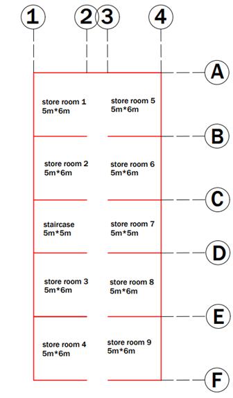
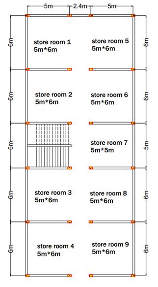
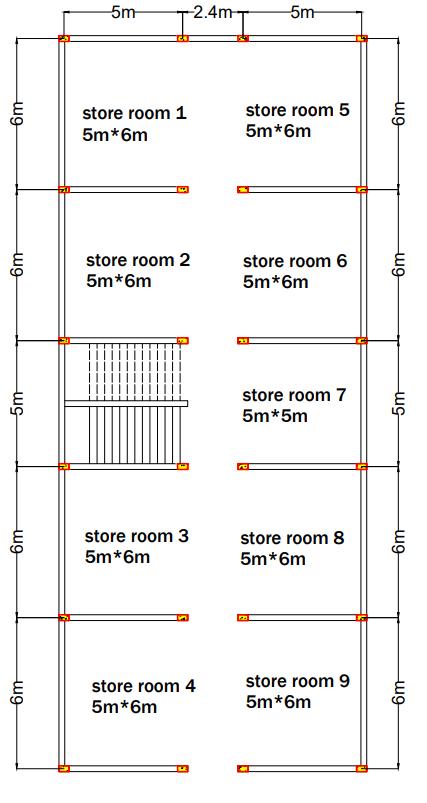
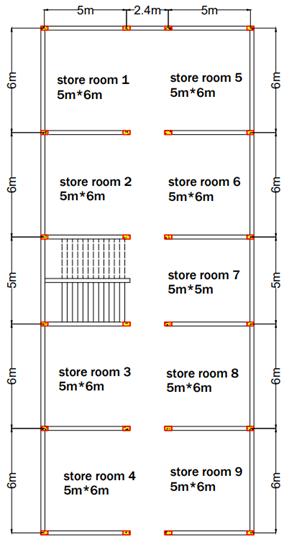
2.3 PLAN AND COLUMN LAYOUT
Aplanbelowisconsideredfortheanalyses.Theplanis drawn in the Auto cad software, and exported to the STAAD.Pro.
2.4 MODELLING AND STRUCTURAL ANALYSIS OF RCC STRUCTURE
Structural analysis, which is an integral part of any engineering project, is the process of predicting the performanceofagivenstructureunderaprescribedloading condition. The plan was imported from the AutoCAD and G+2storeybuildingwasgeneratedinStaad.proanalysiswas performed, the performance characteristics usually of interestinstructuraldesignare:
• Stress
• Deflection
• Supportreactions
• Bendingmoment
• Shearforce
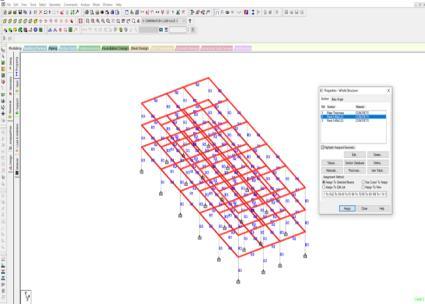
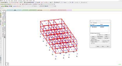
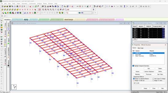
2.4.1 Generating Model Geometry
2.4.2 Specifying Member Property
Thememberpropertiesaretakenasgiven: Thicknessofslab=150mm Beam=450X230mm Column=230X450mm
International Research Journal of Engineering and Technology (IRJET) e-ISSN: 2395-0056
Volume: 11 Issue: 11 | Nov 2024 www.irjet.net p-ISSN: 2395-0072
2.3Assignedmemberproperty
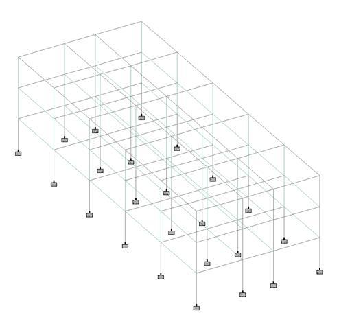
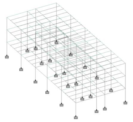
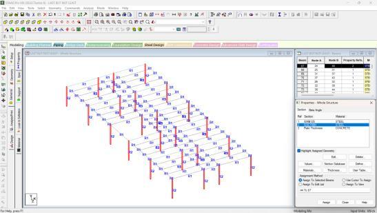
2.4.3 Specifying Supports
Thebasenodesofallcolumnsarerestrainedagainst translationandrotationaboutall thethreeglobal axes.In otherwords,fixedsupportsarespecifiedatthesenodes.

2.4Assignedsupport
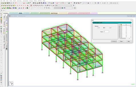
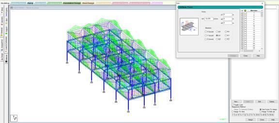
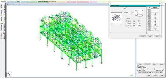
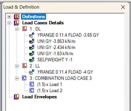
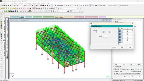
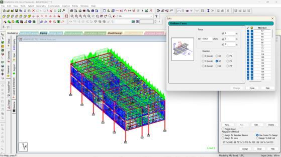
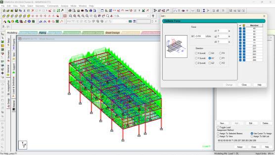
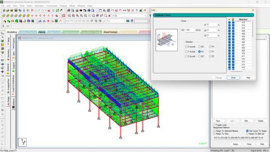
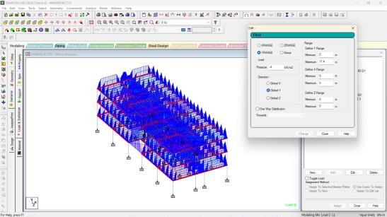
2.4.4 Defining and Assigning Loads
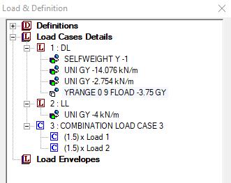
Dead Load
AsperIS875:1987(PartI)
Self-weight=-1kN/m2
Slabload=0.15*25=3.75kN/m2 Wallload
Outerwall=0.23*3*20.4=14.076kN/m2 Parapetwall=0.15*0.9*20.4=2.754kN/m2
Live Load
AsperIS875:1987(PartII)
ForCommercialBuildings Liveload=4kN/m2
International Research Journal of Engineering and Technology (IRJET) e-ISSN: 2395-0056
Volume: 11 Issue: 11 | Nov 2024 www.irjet.net p-ISSN: 2395-0072
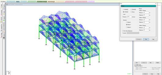
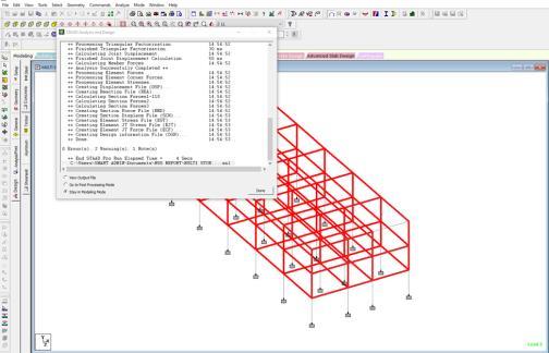
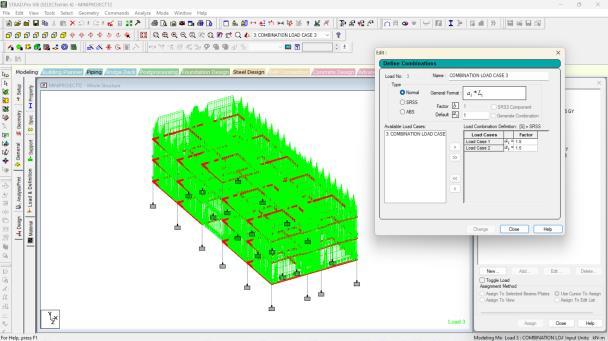
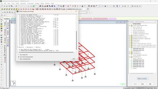
2.4.5 Analysis
The bending moment and the shear force can be studiedfromthegraphsgeneratedbypostprocessingafter the analysis in STAAD.Pro. The below figure shows the diagramsforwholestructure.
2.5 MODELLING AND STRUCTURAL ANALYSIS OF STEEL STRUCTURE
Structural analysis, which is an integral part of any engineering project, is the process of predicting the performanceofagivenstructureunderaprescribedloading condition. The plan was imported from the AutoCAD and G+2storeybuildingisgeneratedinStaad.proandanalysis wasperformed,theperformancecharacteristicsusuallyof interestinstructuraldesignare:
• Stress
• Deflection
• Supportreactions
• Bendingmoment
• Shearforce
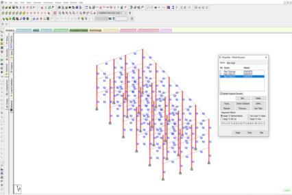
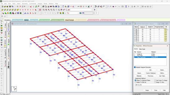
2.5.1 Generating Model Geometry
2.5.2 Specifying Member Property
Thenewtaskistoassigncrosssectionpropertiesfor thebeamandcolumns.Thememberpropertiesareasgiven:
Beam-ISMB125
Subbeam-ISMB125
Column-ISSC150
2.5.3 Specifying Supports
Thebasenodesofallcolumnsarerestrainedagainst translation and rotation about all the three global axis. In otherwords,fixedsupportsarespecifiedatthesenodes.

Fig2.9AssignedSupport
International Research Journal of Engineering and Technology (IRJET) e-ISSN: 2395-0056
Volume: 11 Issue: 11 | Nov 2024 www.irjet.net p-ISSN: 2395-0072
Dead Load
AsperIS875:1987(PartI)
Self-weight=-1kN/m2
Slabload=1x1x0.1x24=2.4kN/m2
Wall load
Outerwall=0.23x3x20.4=2.86kN/m2
Innerwall=0.10x3x6.374=1.912kN/m2
Parapetwall=1x0.1x6.374=0.63kN/m2
Live Load
AsperIS875:1987(PartII)
ForCommercialBuildings
Liveload=4kN/m2
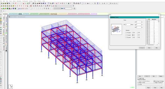
2.5.5 Analysis
The bending moment and the shear force can be studiedfromthegraphsgeneratedbypostprocessingafter the analysis in STAAD.Pro. The below figure shows the diagramsforwholestructure.
International Research Journal of Engineering and Technology (IRJET) e-ISSN: 2395-0056
Volume: 11 Issue: 11 | Nov 2024 www.irjet.net p-ISSN: 2395-0072
After the analysis the results of critical stresses like Bendingmoment,Shearforce,AxialforceandDisplacement are obtained in the post processing mode. The results of criticalstressesarediscussedbelow.
3.1.1 Bending moment
Thereactioninducedinastructuralelementwhenan externalforceormomentisappliedtotheelement,causing theelementtobend.
The maximum bending moment is observed in the beam 128 with the value of 157.752 kN-m.
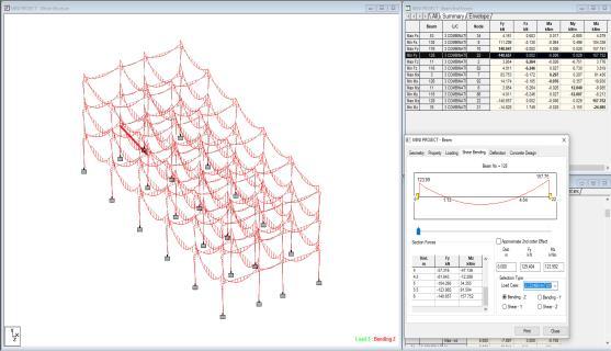
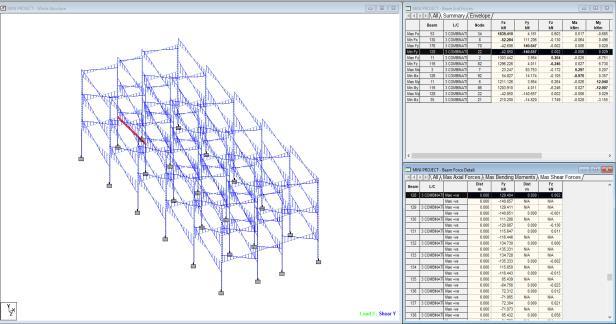
3.1.2 Shear Force
Forceactinginadirectionparalleltoasurfaceortoa planarcrosssectionofabody. The maximum shear force was observed in the beam 128 with the value of -140.657 kN.

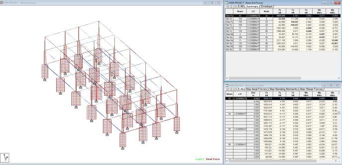
3.1.3 Axial Force
Axialforceistheforcethatactsinthedirectionofthe axisofabody.Thisforcemaybetensileorcompressive. The maximum axial force was observed in the column 53 and the value is 1839.410 kN.
After the analysis the results of critical stresses like Bendingmoment,Shearforce,AxialforceandDisplacement are obtained in the post processing mode. The results of criticalstressesarediscussedbelow.
International Research Journal of Engineering and Technology (IRJET) e-ISSN: 2395-0056
Volume: 11 Issue: 11 | Nov 2024 www.irjet.net p-ISSN: 2395-0072
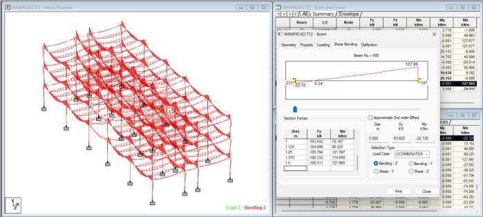
3.2.1 Bending moment
Thereactioninducedinastructuralelementwhenan externalforceormomentisappliedtotheelement,causing theelementtobend.
The maximum bending moment is observed in the beam 495 with the value of 127.965 kN-m.
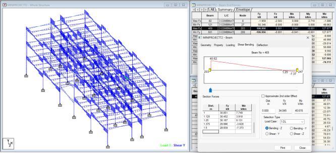
3.2.2 Shear Force
Forceactinginadirectionparalleltoasurfaceortoa planarcrosssectionofabody.
The maximum shear force is observed in the beam 469 with the value of 127.677 kN.
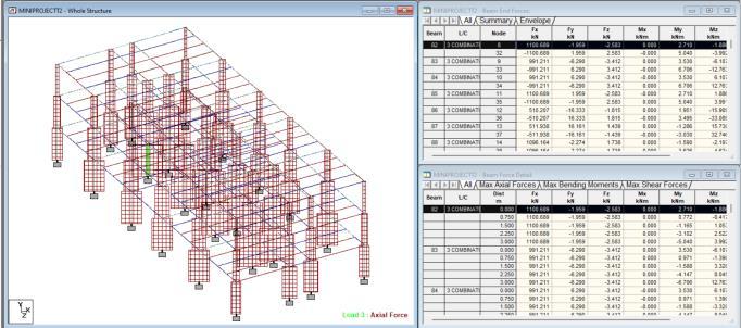
3.2.3 Axial Force
Axialforceistheforcethatactsinthedirectionofthe axisofabody.Thisforcemaybetensileorcompressive. The maximum axial force is observed in the column 8 and the value is 1100.689 kN.
For RCC Structure
1.Maximumbendingmomentinthebeamis157.752kN-m.
2.Maximumshearforceinbeamis-140.657kN.
3.Maximumaxialforceisactingonthecolumnis1839.410 kN.
For Steel Structure
1.Maximumbendingmomentinthebeamis127.965kN-m.
2.Maximumshearforceinbeamis127.677kN.
3.Maximumaxialforceactingonthecolumnis1100.689kN.
• The maximum bending moment and the shear force acting on RCC structure is higher compared to steel structures.
• The strength of steel structures are more than RCC structures. Due to lower weight of steel structure the shear force and the bending moment acting on the structureisalsoless.
• The maximum axial force acting on RCC structure is highercomparedtosteelstructures.
• The member size ratio required for steel structures decreases when the span of column is increased when comparedtothatofRCCstructures
[1] IS: 875 (Part 1), for dead loads, Bureau of Indian Standards,NewDelhi,India.
[2] IS: 875 (Part 2), for imposed loads, Bureau of Indian Standards,NewDelhi,India.
[3] IS: 808: 1989, dimension for steel beam, column sections.
[4] RachskondaDivya(2021)"Comparativestudyondesign ofsteelstructuresandRCCframestructuresbasedon columnspan",Journalsofmaterialstoday,volume46, pageno-8848-8853.
[5] AnuragSaraogi(2018)"AComparisonbetweenRCCand Steel Structure", International Journal of Research in Engineering Science and Management, volume-I, page no-106-108.
[6] Jyothi. D. N (2008) "Comparative analysis of RCC and Steel Structure", International research journal of EngineeringandTechnology,volume-05,pageno-345347.
[7] ShwetaAWagh,(2014)“ComparativestudyofRCCand steel concrete composite structures”, Journal of EngineeringResearchandApplication,volume04,pg. no.369-376.
[8] JohnsonR.P.,(2004)“CompositeStructureofSteeland concrete”,BlackwellScientificpublications,Volume01.
International Research Journal of Engineering and Technology (IRJET) e-ISSN: 2395-0056
Volume: 11 Issue: 11 | Nov 2024 www.irjet.net p-ISSN: 2395-0072
[9] Ankur Tailor, (2016), “Comparative performance evaluationofsteelcolumnbuildingandconcretefilled tubecolumnbuildingunderstaticanddynamicloading”, International symposium of plasticity and impact mechanics,pg.no.1847-1853
BIOGRAPHIES


Mrs. Yashaswi H. V
(AsstProfessor,DepartmentofCivil Engineering,Dr.AIT,Bengaluru)
Vivek R
(UG Student, Department of Civil Engineering,Dr.AIT,Bengaluru)
Shivaparasd B. S
(UG Student, Department of Civil Engineering,Dr.AIT,Bengaluru)
Nithin K. N
(UG Student, Department of Civil Engineering,Dr.AIT,Bengaluru)
Sachin
(UG Student, Department of Civil Engineering,Dr.AIT,Bengaluru)