
International Research Journal of Engineering and Technology (IRJET) e-ISSN: 2395-0056
Volume: 11 Issue: 11 | Nov 2024 www.irjet.net p-ISSN: 2395-0072

International Research Journal of Engineering and Technology (IRJET) e-ISSN: 2395-0056
Volume: 11 Issue: 11 | Nov 2024 www.irjet.net p-ISSN: 2395-0072
Harish M1 , Yaswanth Sai Kumar A 2 , Hemavathi G 3
1 Assistant Professor, Department of Aeronautical Engineering, Hindusthan Institute of Technology
2UG Student, Department of Aeronautical Engineering , Hindusthan Institute of Technology
3 UG Student, Department of Aeronautical Engineering , Hindusthan Institute of Technology
Abstract - The importance of winglet design in aerodynamic engineering, particularly in addressing the challenge of drag reduction and enhancing aircraft performancehasbeenhighlighted.Throughtheutilizationof CATIA-V5 for design and ANSYS for simulation, various winglet configurations were analyzed, revealing distinct efficiencies.Thefindingsemphasizethecriticalroleofwinglets inimprovingfuelefficiency,minimizingdrag,andprolonging engine life, with the hook-shaped winglet demonstrating the highest effectiveness. This research underscores the significanceofselectingoptimalwingletdesignstomaximize aerodynamic performance and operational efficacy in the aviation industry
Key Words: Winglet, Computational Fluid Dynamics, Hook, Wingtip vortex, Aircraft, Induced drag etc.
1.INTRODUCTION
A winglet is a device used to enhance the performanceofaircraftvialoweringtheliftinduceddragas a result of wingtip vortices. It is a vertical or angled extension at the recommendations of each wing. Winglets improveefficiencywiththeaidofdiffusingtheshedwingtip vortex, which in flip reduces the drag due to lift and improvesthewing’sliftoverdragratio.Wingletsincrease the effective aspect ratio of a wing without adding significantly to the structural stress and subsequently importantweightofitsstructure.
Wingletsboomaplane'soperatingefficiencywiththeaidof loweringwhatiscalledinduceddragatthetipsofthewings. Anairplane'swingisformedtogeneratenegativepressure on the upper surface and positive pressure on the lower surfaceastheaircraftmovesforward.Thisunequalpressure creates lift across the upper surface and the plane can go awaythegroundandfly.
Winglets,whichareairfoilsoperatingmuchlikeasailboat tacking upwind, produce a forward thrust inside the circulationfieldofthevorticesanddecreasetheirstrength. Weakervorticessuggestlessdragatthewingtipsandliftis restored. Improved wing efficiency translates to greater payloads, reduced fuel consumption, and an extended cruising range which can allow an air carrier to enlarge routesandlocations.
Duetotheoverallacknowledgementofworldwarming,the aviation enterprise, along with many other transport industriesareconfrontedwithincreasinglystricteremission regulationsfromgovernmentagenciesaroundthearenato lessenthecarbonfootprintsoffutureaircraft.Consequently, intoday’sworldofaviation,wingletsaretypicallymeantto increasetheoverallaerodynamicefficiencyofaircrafts.They reducethevorticesgeneratedalongthesurfaceofthewing via lowering the pressure gradient at the tip of the wing, henceequalizingthepressuredifferencebetweentheupper andlowersurfaceofthewingandminimizingthemagnitude of the vortices generated at some point of flight. This translates to reduced drag and higher average gasoline economicsystemwithoutrequiringanydrasticchangesof anaircraft’sstructureelsewhere.However,variousdesigns mayalsoprovidedifferentgradesofperformancedepending on the physical dimensions, wing form and flight characteristicsoftheaircraft.
Theideaofattachingwingtipdevicestothewingdatestothe end of the 20th century. Several experiments and studies werecompletedwithfewfixed-wingaircrafts,butitbecome nolongeruntilthe1970sduringtheoilcrisisthattheidea got re-enlightened and commercialized among aircraft manufacturesandaviationagencies.
Winglets, along with other wingtip devices can be considered a mainstream element among subsonic and transoniccontemporaryaircrafts.Theyareseeninvarious aircraftsizes,rangingfromsmallsizedpistonpropstolarge jetpropelledtransonicandsupersonicjets.
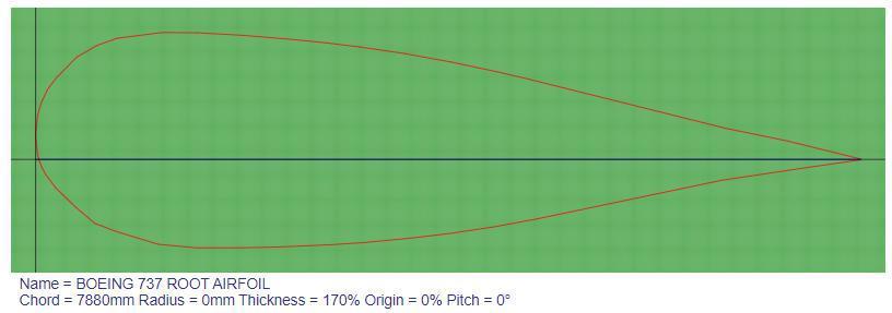
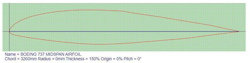
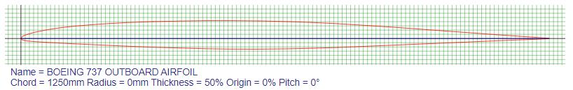
In this paper B737A, B737C and B737D are the airfoils chosen for root section, mid span and tip, as it is ideallysuitedtoanyenvironmentwherespeedisimportant. Theyareshowninfigure1,2and3below.
International Research Journal of Engineering and Technology (IRJET) e-ISSN: 2395-0056
Volume: 11 Issue: 11 | Nov 2024 www.irjet.net p-ISSN: 2395-0072
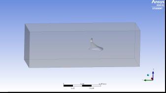
3. COMPUTATIONAL DESIGN
CATIAtoolhasbeenusedtodothecomputational designofhookwingletasshowninfigure4andtable1.The aircraft Wing has been considered as tapered as it gives moreliftathighspeed.
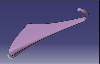
Table -1: Geometriccharacteristicsof
RootChordLength
TipChordLength
Winglet tip Airfoil distance from wingroot
Heightofhookwinglet
Radiusofhookwinglet
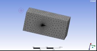
4. MESH GENERATION
1250mm
600mm
16000mm
2400mm
1199mm
Unstructured meshes are meshes with general connectivitywhosestructureisarbitraryandconsequently theconnectivityofelementsmustbedefinedandstored.The elementtypesarenon-orthogonal,includingtriangles(2D) and tetrahedra (3D). The boundary conditions used are showninbelowtable2.Inthispaper,Ansys-Fluenttoolhas
been used to create mesh and to solve the governing equations.
Table -2: Boundaryconditions
Inlet
Outlet
Wing
Wall
VelocityInlet
PressureOutlet
Wall
Wall
5.
CFDsimulationhasbeencarriedoutoverthehook wigletmodelusingAnsys-Fluenttool.InCFD,thek–omega turbulence model is a common two-equation turbulence modelwhichisusedasanapproximationfortheReynoldsaveraged Navier–Stokes equations (RANS equations). The model attempts to predict turbulence by two partial differential equations for two variables, k and ω, with the firstvariablebeingtheturbulencekineticenergy(k)while the second variable omega (ω) is the specific rate of dissipation. The CFD simulation was carried out using komegaturbulencemodelandforthegiventemperatureof 300kandMachnumberof0.52.
International Research Journal of Engineering and Technology (IRJET) e-ISSN: 2395-0056
Volume: 11 Issue: 11 | Nov 2024 www.irjet.net p-ISSN: 2395-0072
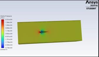
Fig -7:Pressurecontourofhookwinglet
Fromthepressurecontourplotofhookwinglet,as showninfigure7,thereismorestaticpressureattheleading edgeofthewingduetothestagnationpoint.Theflowover the wing at the tip section created more vertices. The pressure acts less at the middle of the wing, while the pressureatthetrailingedgeofthewingcreatesmoredueto flowseparation.
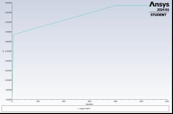
Fig -8:LiftcoefficientplotofhookwingletatzeroAOA
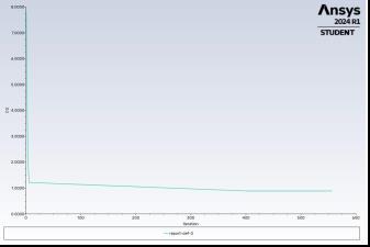
Fig -9:DragcoefficientplotofhookwingletatzeroAOA
Asshowninfigure8and9above,thecoefficientof liftandcoefficientofdragareunsymmetricalatzeroangleof attack.Atzeroangleofattack,thecoefficientofliftvaluesis quitehigher.
Theresultsrevealedthatthehook wingletdesign significantlyoutperformedbyeffectivelyminimizingdrag, reducing wing-tip vortices, and improving overall aerodynamic efficiency. These findings highlight the substantial impact of winglet selection on aircraft performance and operational efficacy. Thus, the optimal integration of winglets, particularly hook winglet designs, holds great promise for realizing significant fuel savings, enhancingflightstability,andprolongingenginelife,thereby advancing the efficiency and sustainability of aviation operations.Overall,theresultshighlightthecriticalroleof winglet design in optimizing aircraft performance and efficiency,withthehookwingletconfigurationsemergingas the most effective solutions for drag reduction and fuel savings.
[1] Alka Sawale , MD Khaleel , S. Jaswanth (2017) design and analysis of winglets, International Journal of Civil Engineering and Technology Volume 8, Issue 5, May 2017,pp.842–850.
[2] Ravikumar Reddy, Prajwalkumar M Patil and G SudarshanReddy(2018),ModelingandCFDAnalysisof FlowOverAircraftSplitWingletandBlendedWinglet, InternationalJournalofAdvancesinScientificResearch andEngineering(ijasre)E-ISSN:2454-8006Volume4, Issue11..
[3] Abinaya.R and Ezhilmaran.G (2016), Analysis of Aerodynamic Efficiency of Different Winglets, international journal of research in aeronautical and mechanicalengineeringissn(online):2321-3051Vol.4 Issue5,Pgs:53-66.
[4] D.Govardhana,M.V.NarasimhaRaob,P.SrinivasaRao, IndradeepKumar,NoelNalli(2023),Effectofwinglet cant angle on the performance of an aircraft wing , MaterialsToday:Proceedings.
[5] Abdelghany,E.E.Khalil,O.E.AbdellatifandG.ElHarriri, “WingletCantandSweepAnglesEffectonAircraftWing Performance”,17MP258thInt.AMMEConference,1921April,2016.
[6] Atique, Md. Abdus S., Asif S.N., Nafisa N. P. and Shuvrodeb B., “Aerodynamics of Winglet: A Computational Fluid Dynamics Study”, Global Science andTechnologyJournal,Vol.3.No.1.March2015Issue..
International Research Journal of Engineering and Technology (IRJET) e-ISSN: 2395-0056
Volume: 11 Issue: 11 | Nov 2024 www.irjet.net p-ISSN: 2395-0072
[7] Dwivedi,PatilM.P.,“DesignandAerodynamicAnalysis of Different Winglet”, (IJIET), V 7, Issue 2, 2 August 2016.
[8] Hussain H. Al-Kayiem, Chelven .A. K. A. K., “An InvestigationontheAerodynamicCharacteristicsof2-D Airfoil in Ground Collision”, Journal of Engineering Science and Technology, Vol. 6, No. 3, P.P.369 – 381, 2011.
[9] Hussain I. Y. and Ali A. H., “Calibration of Low-Speed WindTunnel(LSWT)TestSection”,BaghdadUniversity EngineeringJournal,DossierNo.ME-576.