
International Research Journal of Engineering and Technology (IRJET) e-ISSN: 2395-0056


International Research Journal of Engineering and Technology (IRJET) e-ISSN: 2395-0056
John Nyamekye Ansah1 , John Kojo Annan1
1Department of Electrical and Electronic Engineering, University of Mines and Technology, Tarkwa, Ghana ***
Abstract – In this paper, a novel compact-sized 3-element rectangular patch antenna array with triangular configuration is proposed for radio frequency (RF) energy harvesting applications. The antenna operates effectively within the 2.45 GHz Wi-Fi band and measures a high gain of 11.24 dBi. Rogers RT 5880 is used as the dielectric substrate, with a dielectric constant of ε_r = 2.2, a loss tangent of δ = 0.0009 and the overall antenna size is 165 mm x 200 mm x 1.65 mm. The return loss and Voltage Signal Wave Ratio (VSWR) are recorded as -32.886 dB and 1.0464 respectively indicating minimal reflection and excellent impedance matching.The antennaachieveda totalefficiency of89.41 %. The design and simulation were performed using Computer Simulation Technology (CST) Microwave Studio 2019 software. The proposed antenna demonstrates satisfactory performance, making it suitable for deployment in RF energy harvesting applications.
Key Words: RF Energy Harvesting, Microstrip Patch Antenna, Antenna Array, CST-MWS software
The recent rapid development in technology and improvements in wireless communication systems have resulted in a significant increase in the use of low-power wireless devices [1]. These portable electronic devices facilitatefluidcommunicationamongthemselvesandwith theirusersbyemittingelectromagnetic(EM)energythrough free space. Therefore, their energy requirements must be metinasustainableandcost-effectivemanner[1],[2].Inthe pursuit of adopting renewable energy sources, energy harnessedfromambientenvironmentemergesasanideal solution for powering these low-power devices [3], particularly given the environmental concerns associated withnon-renewablepowersourcessuchasbatteriesandthe cost involved in replacing them [2]. Additionally, these wirelessdevicesareofteninstalledonequipmentwithhigh maintenance costs, in inaccessible places such as ocean depths and dangerous locations [4]. Energy harvesting provides the means of capturing ambient energy from sources such as thermal, wind, solar power and radio frequencies [5]. However, scavenging energy from solar, wind and thermal entails high establishment and maintenance cost [6]. In contrast, RF proves to be most favourableforambientenergyharvestingduetoitslowcost andtheincreasingavailabilityofRFsources[2], including smartphones,radioandTVtransmitters,Wi-Firouters,radar
systemsandmobilebasestations.Asignificantportionofthe EMenergytransmittedbythesesourcesgotowasteinfree space even before reaching their intended target. Consequently, there exist an abundance of EM energy in space that can be trapped and converted into usable DC voltagetopowertheselow-powerelectronicdevices[1],[6], [7].Thus,RFenergyharvestingplaysanimperativerolein facilitatingthedevelopmentofbattery-freedevices[8].
The RF energy harvesting process involves collecting ambient RF power, primarily from wireless power transmissionbetweenatransmitterandreceiveracrosslong distances [2]. This technique has acquired significant researchinterest,drivenbytheincreasingavailabilityofRF energyfromfrequencybandssuchasGSM(900MHz,1800 MHz),UMTS(2100MHz),LTE(2600MHz),Wi-Fi(2.4GHz,5 GHz), and WiMAX (3.5 GHz) [1]. Studies indicate that RF energyisdenselyconcentratedwithinthe1700MHzto2650 MHz range [8]. An RF-EH system typically includes an impedance matching network (IMN), a rectifier, receiving antenna [2], and an energy storage system (ESS) [3] as depictedinFigure1.

The antenna plays a crucial role by gathering ambient RF signals in space and converting them into AC voltage. An optimised matching network is essential to ensure that maximumRFsignalpowerfromtheantennaistransferred to the rectifier circuit. The rectifier then converts this AC voltageintoDCvoltage,whichcanbeusedbythesewireless devicesortochargetheirbatteries.
RFpowerdensityistypicallymuchlowercomparedtoother ambientsourcessuchasthermal,solarandwindduetothe long propagation distance between the transmit and receivingantenna.Theoreticalprinciples,suchastheinverse
Volume: 11 Issue: 11 | Nov 2024 www.irjet.net p-ISSN: 2395-0072 © 2024, IRJET | Impact Factor value: 8.315 | ISO 9001:2008

International Research Journal of Engineering and Technology (IRJET) e-ISSN: 2395-0056
Volume: 11 Issue: 11 | Nov 2024 www.irjet.net p-ISSN: 2395-0072
squarelaw,indicatethatlongerpropagationdistancesresult in reduced power density. Moreover, RF power density is further diminished by free space path loss (FSPL) [1]-[3]. Therefore,itisempiricalforanRF-EHsystemtoemploya highly efficient antenna for effective RF signal capture, a goodIMNtomaximisepowertransfertotherectifier,anda rectifierwithenhancedpowerconversionefficiency(PCE)to generate the expected DC output voltage [3]. RF energy harvesting presents a promising solution for powering miniaturised, self-sustaining, low-power devices, such as wireless sensor networks and Internet of Things (IoT) devices[2].
The microstrip patch antenna (MPA) has emerged as the preferredchoiceforwirelesscommunicationsystems[16] andRF-EHoverthepasttwentytothirtyyears,owingtoits advantageousdesigncharacteristics,includingcompactsize, robustness, lightweight nature, and the capability to be mounted on both planar and non-planar surfaces [10]. Its simplicityandcost-effectivenessfacilitateeasyfabrication onprintedcircuitboards(PCBs)[1],[12].AnMPAcomprises a radiating element known as the patch, which issituated alongsideafeedlineontopofadielectricsubstrate,witha metallic ground plane etched beneath the substrate, as illustratedinFigure2below.
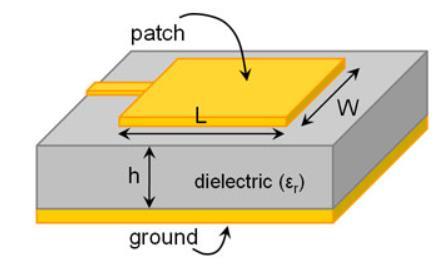
Theradiatingpatchisconstructedfromconductivematerials such as gold or copper and can adopt various random shapes.However,regulargeometries,includingrectangular, square, elliptical, triangular, dipole, circular, and circular ringconfigurations,arepredominantlyemployedforeaseof fabrication[10],[12].
MPAs are versatile and compact, finding applications in numerous wireless devices, including smartphones, wearable technology, GPS receivers, Wi-Fi routers and medical implants [13], as well as in RF energy harvesting systems[14].Giventhattheantennaplaysacriticalfunction indeterminingthequantityofelectromagnetic(EM)energy that can be harvested and transformed into usable DC voltage, it is essential for the antenna to exhibit omnidirectionality (to capture RF energy from all
directions), high gain (to improve the reception of signals from a designated direction), and wide bandwidth characteristics(tofacilitatethecaptureofRFenergyacross multiple frequency bands simultaneously) [9], [13], [14]. Despite the MPA's suitability for RF energy harvesting, it faces several challenges, including low efficiency, poor polarisation, low power-handling capacity, narrow bandwidth[12],andlowgainwhenimplementedasasingle patchantenna[14].Toaddresstheselimitations,thisstudy investigatesandpresentsapatchantennaarraydesignedfor RFenergyharvesting.
Researchers have designed and implemented microstrip patch antennas for RF-EH applications. In RF-EH, it is essential to use receiving antennas with high gain and widebandcharacteristicstooptimiseperformance[13],[14]. High-gainantennasarecrucialastheyenhancethereceived power,therebyimprovingtheoverallDCoutputvoltageof theRF-EHsystem.IninstanceswheretheambientRFenergy source is unknown, omnidirectional antennas are often employed tocapture signalsfromall directions.However, these antennas face challenges such as limited range, reducedefficiency,andlowgain[2].Enhancingthegainof microstrippatchantennascanbeachievedbyincreasingthe widthofthepatchorbyconstructingpatchantennaarrays. While increasing patch width improves both gain and bandwidth,italsoleadstohighersurfacewavelossesand reduces the compactness of the antenna [15]. Conversely, patchantennaarraysofferhighergain,improvedbandwidth, betterpolarisationcontrol,andincreasedefficiency,making them more suitable for RF energy harvesting applications [1].
An edge-fed MPA was designed for Wi-Fi applications, as detailed in [17]. The antenna resonates at two distinct frequencies dueto thepresenceof threerectangular slots carefully created in the radiating element. The operating frequenciesare2.41GHzand5.8GHz,withcorresponding gainsof0.5102dBiat2.41GHzand1.175dBiat5.8GHz.In [9],amultibandfractalantenna,designedintheshapeofa droneandfeaturingadefectedgroundstructure,hasbeen developedandimplementedforRFenergyharvesting.The antennaoperatesatsixdifferentfrequencybands,covering mobile communication services, WLAN frequencies, and WiMAXservices.Thedesignachievesamaximumbandwidth of428.1MHzat5.8GHzandthehighestgain(2.83dBi)is realisedat2.45GHz.Ahexagonal-shapedpatchantennawith a partial ground structure, operating at the 5.8 GHz Wi-Fi frequency,ispresentedin[5].Thepartialgroundstructure facilitatesomnidirectionalradiationcharacteristics,enabling the antenna to capture RF energy from all directions. Additionally,astubisintroducedtoextendthebandwidth andimproveimpedancematching.Theantennaachievesa lowgainof2.88dBiandappreciablebandwidthof680MHz. In [18], the authors designed and simulated a dual-band

International Research Journal of Engineering and Technology (IRJET) e-ISSN: 2395-0056
Volume: 11 Issue: 11 | Nov 2024 www.irjet.net p-ISSN: 2395-0072
MPAusingHFSSsoftware.Theantennaoperatesat3.6GHz and5.25GHzfrequencies,exhibitingbandwidthsof300MHz and 2110 MHz, with corresponding gains of 2.77 dBi and 3.34 dBi, respectively. Although the antenna operates effectivelyatthesetwoseparatefrequencies,theradiation efficiency at 5.25 GHz is recorded at 69.96%, indicating a needforimprovement. Acompactsizeddual-bandMPAis designed and analysed [1] for RF energy harvesting applications.FR-4isusedasthesubstrate,withheightof1.6 mm.Theantennaworksat2.4GHzand5.2GHzfrequencies andhasoveralldimensionas28×47×1.6mm³.Thegainat the two operating frequencies is measured at 1.6 dBi and 3.95dBi,withcorrespondingbandwidthsof340.5MHzand 293.4 MHz. While the antenna demonstrates favourable radiation efficiencies at both frequencies, its overall efficiency remains moderate. A reconfigurable MPA is designed and presented in [16], featuring three switching modes:OFF-OFF,ON-OFF,andON-ON.Thefrequencytuning isachievedusinganRFMEMSshuntcapacitorswitch.The antennaachievesabandwidthof110MHzandmaintainsa return loss below -20 dB across all switching modes. The correspondinggainsforthethreemodesare4.2dBi,4.2dBi, and 4.3 dBi, respectively. In [7], a b-shaped MPA was presented. To accelerate the simulation process, machine learningtechniqueswereemployed.Apartialgroundplane was implemented to provide the antenna with omnidirectional radiation characteristics. The antenna supports frequencies for both mobile communication and WLAN. It demonstrates total and radiation efficiencies exceeding85%acrossallfourresonantfrequencies,witha maximum gain of 4.74 dBi observed at the 2.6 GHz LTE frequency.In[8],awidebandpatchantennawithtwoopen ringresonatorswasdesignedandimplementedforRF-EH applications.Theantennarecordsmaximumgainsof5dBiat 2.45GHz,and2GHz In[19],acircularmonopoleMPAwas designedandimplementedforultra-widebandapplications. Theantennaobtainsagainof5.92dBiandabandwidthof 8.2 GHz, from 1.8 GHz to 10 GHz. In [10], an MPA was simulated and analysed using CST software for wireless applications. The antenna exhibits resonance at 3.5 GHz, coveringabandwidthof144.1MHz.Itobtainsareturnloss valueof -30.611dBandagainof6.05dBi. Researchers in [14] simulated and fabricated a 2x2 patch antenna array, specificallytargetingtheGSM1800MHzfrequencyband.It obtained a gain of 9.2 dBi, indicating its potential as an effective candidate for RF energy harvesting. In [13], a circular concentric MPA with seven rectangular patch elements was designed and simulated using CST-MWS
software.Initially,asingle-elementantennawasdeveloped, achieving a gain of 8.22 dBi at the resonant frequency. Subsequently, the proposed antenna array wassimulated, resultinginagainof15.8dBi,whichisapproximatelytwice thegainofthesingle-elementantenna.Thesefindingsclearly shows that the implementation of antenna arrays significantly enhances gain. In [4], a 2.4 GHz 2x4 antenna array was designed and simulated using MATLAB for RF energyharvestingapplications.Theantennareachedahigh gain of 17.5 dBi However, the presence of high side lobe levels adversely affects the radiation efficiency, thereby reducing the overall performance of the antenna. In [14], [13], and [4], it has been shown that antenna arrays significantly enhancegain, whichisa critical factorfor RF energyharvesting.Theoretically,increasingthenumberof elements in an array leads to higher gain, as it results in constructive interference that allows the antenna to concentrateradiatedpowerinaspecificdirection,thereby improvingbothgainanddirectivity[12].However,whilean increasednumberofelementsgenerallyboostsgain,factors such as inter-element spacing can introduce challenges, includinghighersidelobelevels andimpedancematching difficulties [15]. Patch antenna arrays are typically constructedinsquareorrectangularconfigurations,asseen in [14] and [4]. Common configurations include 1x2, 1x4, 2x2, 2x4, and 3x3 arrays [12]. In [13], a seven-element circularconcentricpatcharrayachievedahighgainof15.8 dBi.Thispaperintroducesanoveltriangularconfiguration of a three-element rectangular patch antenna array, resonatingat2.45GHzforRF-EHapplications.Thedesign and simulation are performed using CST-MWS 2019 simulationsoftware.
We began our work by designing and simulating a singleelementinset-fedrectangularMPAusingCST-MWSsoftware. RogersRT5880wasusedasthedielectricsubstrate,witha heightofh=1.65mm,adielectricconstantofε_r=2.2,anda losstangentofδ=0.0009.Thepatchandgroundplanewere fabricated from annealed copper with a thickness of Mt = 0.035 mm. The operating frequency was selected as 2.45 GHz, a widely used frequency band, making it a suitable candidateforharvestingambientRFenergytopowerlowpower wireless devices. Figure 3 below presents the structureanddimensionofthe1x1patchantenna.

International Research Journal of Engineering and Technology (IRJET) e-ISSN: 2395-0056
Volume: 11 Issue: 11 | Nov 2024 www.irjet.net p-ISSN: 2395-0072


Fig.3Designstructureanddimensionofthe1x1patchantenna(a)topview(b)bottomview
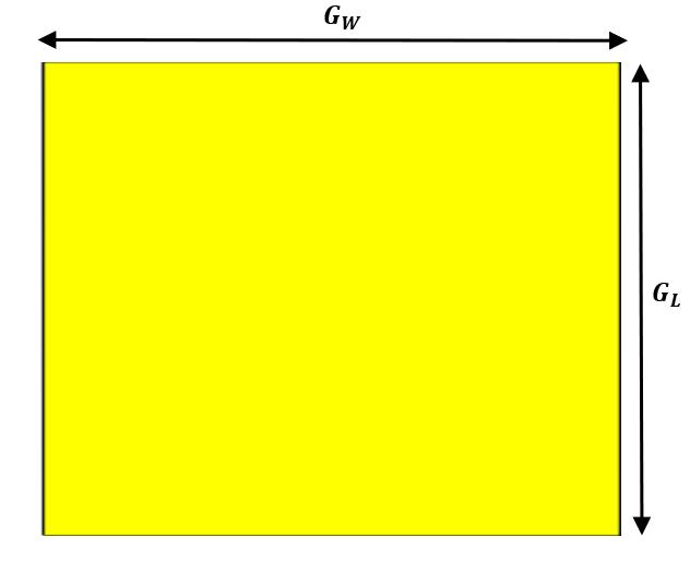
Additionally,anoveltriangularconfigurationofthethreeelement rectangular patch antenna array was developed buildinguponthedesignofthe1x1patchantenna,tofurther improve performance and increase suitability for the intendedapplication.

(c)
(d)
Fig.4Designstructureanddimensionoftheproposed3 –elementpatchantennaarray(c)topview(d)bottomview
Table 1 below presents the dimensions of the proposed three-elementpatchantennaarray.
Table -1: DimensionoftheProposedThree-Element PatchArray
4. Results and Discussion
The simulation results and analysis of both the singleelement patch antenna as well as the proposed threeelementantennaarrayarepresentedinthissection.
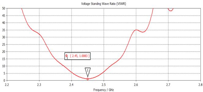
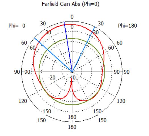
Thesimulationresultsshowthattheantennaresonatesat 2.45GHz,asobservedfromthescatteringparameter|S11|, with a return loss of -47.635 dB. The antenna operates effectively within the frequency range of 2.4319 GHz –2.4679GHz,givingabandwidthof36MHz.Attheresonant frequency,theVSWRisseenas1.0083,indicatingminimal reflectionandexcellentimpedancematching[12].Thegain and directivity are obtained as 6.966 dBi and 7.784 dBi respectively.Additionally,theradiationandtotalefficiencies

International Research Journal of Engineering and Technology (IRJET) e-ISSN: 2395-0056
Volume: 11 Issue: 11 | Nov 2024 www.irjet.net p-ISSN: 2395-0072
ofthe1x1patchantennaarebothobservedtobe82.84%, demonstratinggoodoverallantennaperformance.The|S11| graph and VSWR are presented in Figure 5 and 6, respectively.Thegainand3Dradiationpatternareshownin Figure7whilethe2DpolarplotsaregiveninFigures8(a) and8(b).




4.2 Simulation Results of the 3-element Patch Antenna Array
Thesimulationresultsshowedthat,the3-elementantenna arrayresonatesat2.45GHz,havingareturnlossof-32.886 dB.Theantennahasabandwidthof31.5MHz,andoperates effectivelybetween2.4342GHzand2.4657GHz.TheVSWR is observed to be 1.0464, and the realised gain and directivity is obtained as 11.24 dBi and 11.72 dBi respectively.Furthermore,theradiationefficiencyandtotal efficiency are both observed to be 89.45 % and 89.41 %, indicating the antenna’s high performance in energy transmissionandoverallefficiency. Figure9and10present the|S11|graphandVSWRofthe3-elementpatchantenna array. Additionally, the gain and 3D radiation pattern are giveninFigure11andthe2DpolarplotsaregiveninFigures 12(a)and12(b).

International Research Journal of Engineering and Technology (IRJET) e-ISSN: 2395-0056
Volume: 11 Issue: 11 | Nov 2024 www.irjet.net p-ISSN: 2395-0072
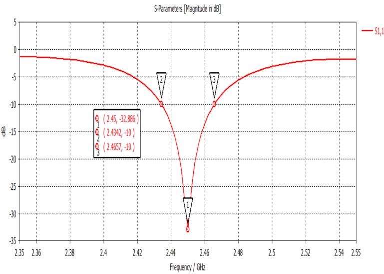
Fig.9S11parameteroftheproposed3-elementpatch antennaarray
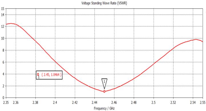
Fig.10VSWRgraphoftheproposed3-elementpatch antennaarray

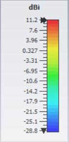

Fig.113DRadiationpatternoftheproposed3-element patchantennaarray


Fig.12(a)E-planeand(b)H-planeradiationpatternsof the3-elementpatchantennaarray
Table2belowprovidesasummaryofthesimulationresults, highlightingthekeyfindings.
Table -2: Summaryofsimulationresultsandkeyfindings

International Research Journal of Engineering and Technology (IRJET) e-ISSN: 2395-0056
Volume: 11 Issue: 11 | Nov 2024 www.irjet.net p-ISSN: 2395-0072
Inthisresearch,itisobservedthatthegainofanantennaincreasessignificantlywithanincreaseinthe numberofpatch elements.However,thisisdependentonensuringthenecessaryinter-elementdistancebetweenthepatches.Patchantenna arraysareusuallyconstructedinsquareandrectangularconfigurations,asseenin[4]and[14].Popularsquareorrectangular configurationsinclude1x2,1x4,2x2,2x4and3x3[12].In[14],thegainofa2x2rectangularpatchantennaarrayisseenas9.2 dBi.Thegainsfor2x2,2x3and2x4triangularpatcharraysdesignedin[20]wererecordedas11dBi,10.4dBiand10.3dBi respectively.The7-elementrectangularpatchantennaarraywithcircularconcentricconfigurationgaveagainof 15.8dBi, whilethe2x4rectangulararrayin[4]measured17.5dBiasgain.In[4],itisrealisedthat,eventhoughitproducesaveryhigh gainof17.5dBi,theoverallantennaefficiencyisexpectedtobefairlylowerduetohighsidelobelevelsinitsradiationpattern. Inthispaper,acompact3-elementrectangularpatchantennaarraywithtriangularconfigurationisdesignedforRFenergy harvestingapplications.Thisantennameasuresagainof11.24dBiattheresonantfrequency,whichishigherthanthegains observedinthe2x2arrayin[14]andthe2x2,2x3and2x4in[20].Itisnoticedthatasidefromincreasingthenumberofpatch elements,ensuringtherequiredinter-elementdistancesignificantlyimpactsthegainoftheantenna,includingtheshapeofthe patchelement.Table3belowpresentsacomparisonbetweentheproposeddesignandpreviousrelatedworks.
Table -3: Acomparativeanalysisoftheproposeddesigntopreviousrelatedworks.
Inthispaper,anoveltriangularconfigurationofa3-elementrectangularpatchantennaarrayisdesignedandproposedforRF energyharvesting.Theantennaachievesahighgainof11.24dBiat2.45GHzwithradiationandtotalefficienciesof89.45%and 89.41%respectively.Theantennaoperateseffectivelybetween2.4342GHzand2.4657GHzcoveringabandwidthof31.5MHz. ThereturnlossandVSWRareobservedtobe-32.886dBand1.0464respectively,indicatingminimalreflectionandexcellent impedancematching[12].Theproposedantennademonstratessatisfactoryperformance,makingitsuitablefordeploymentin RF energy harvesting applications. Future work will focus on designing an efficient rectifier using ADS (Advanced Design System)softwaretoconvertRFpowerintoDCpower,therebyenablingenergyharvestingwithinthe2.45GHzWi-Fiband. Additionally,furtherresearchshouldexplorevariousarrayconfigurationstooptimisegain.Thisapproachcouldpotentially achievehigh-gainperformancewithfewerpatchelements,enhancingtheefficiencyofantennasystemsinhigh-gainapplications.
[1] B. Kanboz and M. Palandöken, “Microstrip patch antenna array design for RF energy harvesting applications,” Eur. J. Sci. Technol.,no.49,pp.34–37, 2023.
[2] Y. C. Lee et al., “High-Performance Multiband Ambient RF EnergyHarvestingFront-End System forSustainableIoTApplications AReview,” IEEE Access, vol. 11, pp. 11143–11164, Jan. 2023, doi: 10.1109/access.2023.3241458.

International Research Journal of Engineering and Technology (IRJET) e-ISSN: 2395-0056
Volume: 11 Issue: 11 | Nov 2024 www.irjet.net p-ISSN: 2395-0072
[3] M. Cansız and D. Altınel, “Multiband RF energy harvesting for zero-energy devices,” Electrical Engineering, vol. 105, no. 3, pp. 1013-1023, 2023. doi:10.1007/s00202-022-00769-9.
[4] U.Nnamdi,B.Omijeh,andI.Asianuba,“Designand optimizationofa2.4GHzantennaarrayforenergy harvesting,” Eur. J. Theor. Appl. Sci.,vol.1,no.6,pp. 676–683,2023.
[5] R.DasandG.S.Baghel,“Designofahexagonalpatch defected ground antenna for energy harvesting applications,” in Proceedings of the International Conference on Innovations in Electronics and Communication Engineering (IECE),2024,pp.1-5.
[6] R. Agrahari et al., “Triple-band metasurface absorber for RF energy harvesting applications,” Microwave Opt. Technol. Lett., vol. 65, no. 8, pp. 2252–2261,2023.
[7] Y. E. Kuşin and M. Palandöken, “Machine learning based b-shaped monopole antenna for RF energy harvesting applications,” Int. J. Adv. Nat. Sci. Eng. Res.,vol.7,no.6,pp.33–38,2023.
[8] M. Zeng, Z. Li, Y. Ding, and X. Lin, “A wide‐band antenna with dual open rings resonator for RF energy harvesting,” Microwave and Optical Technology Letters,vol.64,no.11,pp.2019–2023, Jun.2022,doi:10.1002/mop.33383.
[9] M.M.HasanandA.M.A.Sabaawi,“DroneShaped FractalAntennawithDefectedGroundStructurefor RF Energy Harvesting Applications,” Periodica Polytechnica Electrical Engineering and Computer Science,Jun.2024,doi:10.3311/ppee.24041.
[10] Md. S. Rana, Md. N. Khurshid, S. K. Joy, Md. S. I. Sourav,Md.J.Hassan,andMd.J.Nazmul,“A3.5GHz microstrip patch antenna design and analysis for wireless applications,” Indonesian Journal of ElectricalEngineeringandComputerScience,vol.32, no. 2, p. 828, Sep. 2023, doi: 10.11591/ijeecs.v32.i2.pp828-837.
[11] N. U. Khan, S. Ullah, F. U. Khan, and A. Merla, “Developmentof2400–2450MHzfrequencyband RFEnergyharvestingSystemforLow-PowerDevice Operation,” Sensors, vol. 24, no. 10, p. 2986, May 2024,doi:10.3390/s24102986.
[12] Y. Huang and K. Boyle, Antennas: From theory to practice. 2008. [Online]. Available: https://www.amazon.com/Antennas-TheoryPractice-Yi-Huang/dp/0470510285
[13] A.A.Kabeel,A.H.Hussein,A.E.ElMaghrabi,andR. H.Elabd,“Designofacircularconcentricmicrostrip
patch antenna array for WI-FI band energy harvesting,” Journal of Engineering ResearchEgypt/JournalofEngineering Research,vol.7,no.5, pp. 156–159, Nov. 2023, doi: 10.21608/erjeng.2023.237512.1253.
[14] T.SharmaandG.Saini,“MicrostripAntennaArray for RF Energy Harvesting System,” International Journal of Advanced Information Science and Technology (IJAIST), vol. 48, no. 48, pp. 1-5, Jan. 2016.
[15] R. Garg, P. Bhartia, I. Bahl, and A. Ittipiboon, MicrostripAntennaDesignHandbook.Norwood,MA: ArtechHouse,2001.
[16] J. Navarajan, M. R. E.Jebarani, and V. G. Krishnan, “Frequency Reconfigurable Microstrip Patch AntennaforMultibandApplicationswithRFMEMS Shunt Capacitor Switch,” International Journal of Intelligent Systems and Applications in Engineering, vol.11,no.3s,pp.01-07,2023.
[17] S. Küçükcan and A. Kaya, “Dual-Band microstrip patch antenna design for Wi-Fi applications,” European Journal of Science and Technology, Mar. 2022,doi:10.31590/ejosat.1084147.
[18] P. Ramineni, “Design and analysis of a Dual-Band Microstrip patch antenna for sub-6 GHz applications,” Journal of Engineering Research and Reports,vol.26,no.7,pp.210–221,Jun.2024,doi: 10.9734/jerr/2024/v26i71204.
[19] B. S. Taha and H. M. Marhoon, “Simulation and manufacturing of modified circular monopole microstrip antenna for UWB applications,” InternationalJournalofAdvancesinAppliedSciences, vol. 10, no. 1, p. 70, Mar. 2021, doi: 10.11591/ijaas.v10.i1.pp70-78.
[20] T. Jayanthy, J. Harini, A. Haseena, and N. C. L., "DesignandAnalysisofTriangularPatchAntenna Array," International Journal of Engineering Research and Technology (IJERT),vol.8,no.12,pp. 123-128,2024.