
International Research Journal of Engineering and Technology (IRJET) e-ISSN: 2395-0056 p-ISSN: 2395-0072
Volume: 11 Issue: 12 | Dec 2024 www.irjet.net


International Research Journal of Engineering and Technology (IRJET) e-ISSN: 2395-0056 p-ISSN: 2395-0072
Volume: 11 Issue: 12 | Dec 2024 www.irjet.net
YUVARAJ R1 , Dr. ADINATH JAIN2 , Dr. C SUNANDA3
1Student, EEE Dept., RV College of Engineering, Bengaluru, India
2 Assistant Professor, EEE Dept., RV College of Engineering, Bengaluru, India
3 Assistant Professor, EEE Dept., RV College of Engineering, Bengaluru, India
Abstract - This paper work is aimed at design and analysis of PV based Luo Converter Fed BLDC Motor. The super-lift Luo converter uses a voltage lift technique to improve performance. Unlike traditional converters that increase voltage in an arithmetic progression, the superlift converter does so geometrically, enhancing power transfer gain. This design effectively boosts voltage for lower input levels, making it suitable for driving BLDC motors. Compared to classical buck converters, which generate significant output voltage ripples and parasitic effects, the Luo converter integrates additional filter elements,suchas inductors and capacitors, tosmoothout the output and reduce ripples. By varying the duty cycle, the Luo converter can function as both a buck and boost converter, making it a versatile choice for BLDC motor drives.
Key Words: Luo-converter, BLDC motor, Pulse Width Modulation, Variable Load, DC-DC Converter, DC-AC Converter, H-Bridge Multilevel Inverter, Photo Voltaic, Matlab, Simulink
In recent days the use of renewable energy is widely increasing day by day. Among them, Solar Energy is considered as one of the important energy sources since these are environmental friendly and produces electric power without causing pollution. Therefore, Solar Photo Voltaic(PV)panelsarepreferredthatarereadilyavailable. Incomparisontootherrenewableresources,thePVsystem is quiet, stationary, devoid of mechanical parts, and has minimal production and operating expenses. There is a growingtendencyintheglobalsectorandintheoperationof differentindustrialfacilitiesfortheuseofphotovoltaicasa source of electrical energy. Numerous variables, including thedeclineinthecostofproducingphotovoltaicpowerper kW, the increase in the price of fossil fuels, and the advancement of efficient photovoltaic energy conversion technologies,aredrivingthistrend[1]-[4].
Thephotovoltaiccellsgenerateelectricalenergyusingthe sunlight.APVpanelisformedofPVcellsconnectedinseries, parallelorseries-parallelthatisworkingcommonlywitha DC-DC converter and stores electrical energy in a battery array.DC-DCconvertersareelectronicdevicesthatareused
tochangeDC electrical power efficientlyfromonevoltage leveltoanother.Thecontrolofvoltageisdonebycontrolling thedutyratiooftheswitch[5].SwitchesusedareMOSFET’s, transistors,GTO’s,IGBT’sdependinguponthecircuitorthe powertransfercapability.Thecontrolofoutputvoltagetoa constant magnitude is achieved by the help of a feedback. Theuseofoneormoreswitchesforthepurposeofpower conversioncanberegardedasaSMPS[6]-[10].
In recent trends, in various industries, DC-DC conversion playsasignificantroleforvariousapplicationsandthereare various types of DC-DC conversion techniques to improve thevoltagegainaswellasefficiency.InDC-DCconversion step-up chopper boosts the output voltage whereas step downchopperbuckstheoutputvoltage[11]-[14].Duetoa lot of research in DC-DC conversion more topologies developed,generally,thesetopologiesarecategorizedinto withandwithouttransformer.Thetransformer-lessDC-DC conversionhasledtoareductioninthesize,weight,costand losses.Therearemanyvoltagebuildingtechniquesadopted in conversion stages, namely, voltage lift technique and super-lifttechniqueinthecaseofLuoDC–DCconverters [15]-[18].
Luo converters developed from the fundamental DC – DC converterhasasimpleandcheaptopologyaswellprovide highvoltagegain,betterefficiencyandlowestrippleatthe output. In the voltage lift technique, the output voltage is increasedstepbystepinarithmeticprogression.However, in the super-lift technique, the output voltage increases geometrically. Two types of super- lift techniques are Positive Output Super-lift Luo Converter (POSLC) and Negative Output Super- lift Luo Converter (NOSLC) [19][20]. Luo converters are DC-DC Switching Mode Boost converters.Aboostconverter(step-upconverter)ispower converterwithanoutputdcvoltagegreaterthanitsinputdc voltage.Luoconvertersareaclassofconvertersprovidinga high gain with relatively lesser number of components. Although Luo converters provide a high gain, when cascaded, the gain increases stage by stage only in ArithmeticProgressioni.e.theseconvertersusesthevoltage lift(VL)technique[21].
In order to solve this discrepancy in the Classical Luo Converters,anotherclassofconverterscalledSuper-liftLuo Converterswasdeveloped.Whilethepositiveaspectsofthe Classical Luo Converters are retained in Super-lift

International Research Journal of
Volume: 11 Issue: 12 | Dec 2024 www.irjet.net
converters, Super-lift converters also have the advantage that the gain in this converter increases in geometric progression,stagebystage[22].
ThestudyoutlinesthedesignofaLuoconverterspecifically engineeredtoprovideaboostedvoltagefordrivingaBLDC motor, especially when input voltages are low. Unlike traditional converters, that often struggle with excessive voltage ripples and parasitic effects in BLDC motor applications,theLuoconverterismoreeffective.Itsoutput stage,featuringaninductorandcapacitor,inherentlyactsasa filter, efficiently storing and delivering energy to the load. Thisresultsinasmoothandstableoutputvoltage.TheLuo converter's ability to function both as a buck and a boost converterbyvaryingthedutycyclemakesitwell-suitedfor theBLDCmotordriveapplication.
Additionally,aBLDCmotordrivewithaPIcontrollerscheme necessitates a constant DC supply for the voltage source inverter (VSI) using a Pulse Width Modulated (PWM) techniqueforspeedcontrol.Themotor'sspeedisinfluenced by the DC voltage at the inverter's front end, allowing variable speed operation by adjusting the DC link voltage withfundamentalfrequencyswitching.APIcontroller-based speedcontrolloopisemployedtoregulatetheDCvoltagein accordancewiththedesiredspeed,ensuringprecisecontrol andefficientoperationoftheBLDCmotor.
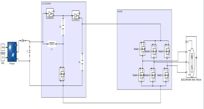
The luo converter operates based on the speed controller consists of two loops, speed control loop senses the reference speed and measured speed and the error is provided for PI controller generates voltage reference is providedtovoltagecontrolloopgeneratesdutyratiobased on the error in voltage of reference and converter output voltage.ThegenerateddutyratioisprovidedforPWMpulse generation for the luo converter. The output of the luo converterisprovidedtotheinverteroperatesbasedonthe pulses generated using hall signals. The inverter output is providedtotheBLDCmotorof400V,50Hz,2KVA,1500rpm. AnelectroniccommutationoftheBLDCmotorincludesthe proper switching of VSI in such a way that a symmetrical current is drawn from the dc link capacitor for 120◦ and placedsymmetricallyatthecenterofeachphase.AHall-effect
and
(IRJET) e-ISSN: 2395-0056 p-ISSN: 2395-0072
positionsensorisusedtosensetherotorpositiononaspan of60◦ ,isrequiredfortheelectroniccommutationoftheBLDC motor.Alinecurrentiabisdrawnfromthedclinkcapacitor whose magnitude depends on the applied dc link voltage (Vdc),backelectromotiveforces(EMFs),resistances(Raand Rb),andselfinductanceandmutualinductance(La,Lb,andM) ofthestatorwindings.
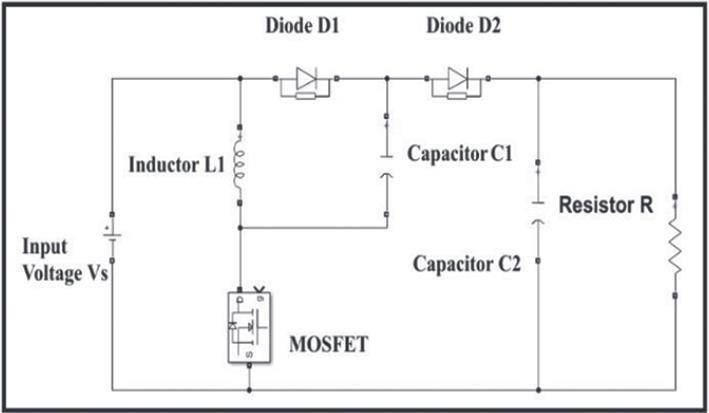
Figure2:CircuitDiagramofLuoConverter
The circuit consists of a MOSFET switch S, Inductor L1, Diodes D1 and D2, capacitors C1 and C2, and a load resistanceR.Figure2.3showsthecircuitdiagramofPositive OutputSuper-LiftLuoConverter(POSLC).
AnalysisofthePOSLCbeginsbymakingtheseassumptions:
Thecircuitisoperatinginsteadystate
Theinductorcurrentiscontinuous(alwayspositive)
The capacitor is very large, and the output voltage is heldconstantatvoltageVo
TheswitchingperiodisK;theswitchisclosedfortime DKandopenfortime(1-D)K.
Thecomponentsareideal.
Mode 1: Duringmode1operation,theswitchSisconsidered tobeinONstatethereby,capacitorC1getschargedtoVs The currentiL1flowingthroughinductorincreaseswithvoltage Vs.TheinputcurrentiswillbeequaltoiL1+ic1.Themode1 operation is depicted clearly through Figure 3. When the switchisclosed,thediodeD1isforwardbiasedanddiodeD2 isintheOFFstate.
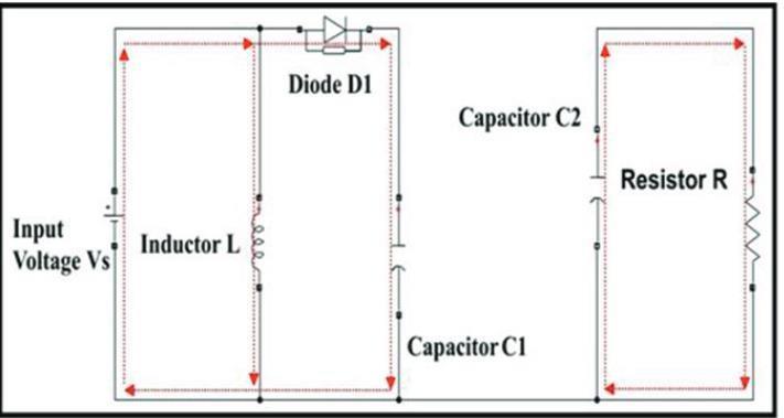
Figure3:EquivalentCircuitofLuoConverterWhenSwitch IsTurnedON

Volume: 11 Issue: 12 | Dec 2024 www.irjet.net
International Research Journal of Engineering and Technology (IRJET) e-ISSN: 2395-0056 p-ISSN: 2395-0072
Mode 2: Figure 4 clearly shows the mode 2 operation of positive output super-lift Luo converter. During mode 2 operation,switchSisconsideredtobeinOFFstate,diodeD1 isreversedbiasedandD2becomesforwardbiased.During mode2operation,inputcurrentwillbeequaltoiL1 (=ico).
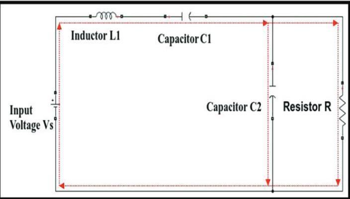
Figure4:EquivalentCircuitofLuoConverterWhenSwitch IsTurnedOFF
The voltage across the capacitor C1 is charged to Vin. The current iL1 flowing through inductor L1 increases with voltage Vin during switching- ON period KT and decrease withvoltage(Vo-2Vin)duringswitching-OFFperiod(1-K)T. Therefore,therippleoftheinductorcurrentisiL1.Theinput currentiin isequalto(iL1+iC1)duringswitching-on,andonly equal to iL1 during switching-off. Capacitor current iC1 is equaltoiL1 duringswitching-off.Insteady-state,theaverage chargeacrosscapacitorC1shouldnotchange.
TheTable1givestheinformationabouttheinputandoutput parameters required for the design of the PV based Luo converterfedBLDCmotor.
Table1:DesignSpecifications
PV Array
Module ApolloSolarEnergy ASEC-300G6M (Polycrystalline Module)
Current Resistance 75Ω
BLDC Motor Power 2kW
Voltage 400V
Frequency 50Hz
Speed 1500rpm
Thedutycycle,Dforproposedconverter,iscalculatedas

Where,Vo=OutputVoltage VIn=InputVoltage

Thecalculationofripplecurrentofboostinductanceis performedbythefollowingrelation:

Where,Io=OutputCurrent

Thecalculationofinductanceisperformedbythefollowing relation:

Where,R=Resistance FS=SwitchingFrequency

Theswitchingtimeperiod,Tsiscalculatedfromthe switchingfrequencyasshownbelow:


Thecapacitancevalueattheloadsideisprovidedbythe followingrelation:

Therippleoutputvoltageiscalculatedwiththefollowing equation:

International Research Journal of
Volume: 11 Issue: 12 | Dec 2024 www.irjet.net
ThecouplingcapacitancevalueofLuoconverteris providedbythefollowingrelation:


Table2:LuoConverterDesignParameters (7)
SYMBOL PARAMETERS

Ta=Grossmechanicaltorque(or)motortorque (8)


ThePVpanelisprovidingvoltageof35Vandpower2KWto theLuoconverter. Theluoconverteroperatesbasedonthe
(IRJET) e-ISSN: 2395-0056 p-ISSN: 2395-0072
speed controller consists of two loops, speed control loop senses the reference speed and measured speed and the error is provided for PI controller generates voltage reference isprovidedtovoltagecontrolloop generatesduty ratiobasedontheerrorinvoltageofreferenceandconverter outputvoltage.ThegenerateddutyratioisprovidedforPWM pulsegenerationfortheluoconverter.Theoutputoftheluo converterisprovidedtotheinverteroperatesbasedonthe pulses generated using hall signals. The inverter output is providedtotheBLDCmotorof400V,50Hz,2KVA,1500rpm. Figure 5, shows the simulation circuit of the proposed system.
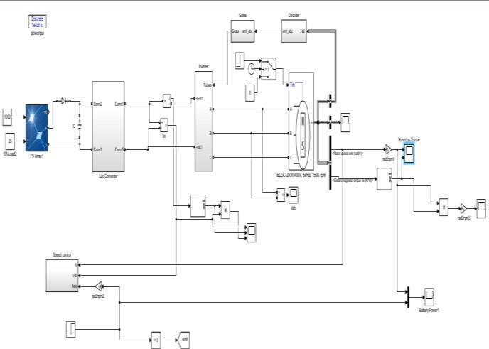
Fig5:SimulationCircuit
Figure6,showsLuoconverteroutputvoltage,currentand powerwaveform.Thevoltageisaround80Vfromt=0to0.5s (500rpm)andincreasedto250Vfromt=0.5s(1500rpm).The currentisnearlyzerofromt=0to1s(Noload)andincreased to3Afromt=1sto2s(25%load)andagainincreasedto12A att=2s(Fullload)
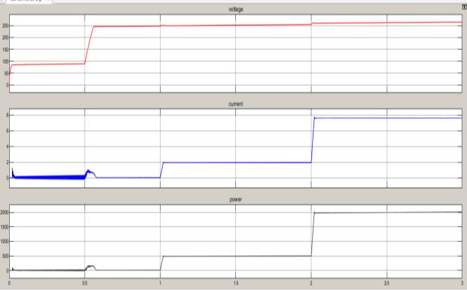
Figure6:LuoConverterOutputVoltage,CurrentandPower Waveform
Figure 7, shows the speed torque waveforms of the BLDC motor.Initiallythespeedreferenceis500rpmandchanged to1500rpmatt=0.5s.Alsothemotoroperatesundernoload conditionfrom t=0to 1sandthetorque increasesto3Nm (25%load)att=1sandagainincreasedto12Nm(Fullload)at t=2s.

International Research Journal of
Volume: 11 Issue: 12 | Dec 2024 www.irjet.net
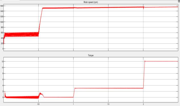
Figure7:SpeedandTorqueWaveformsofBLDCMotor
Similartodccurrent,thestatorcurrentalsovariesduetothe loadchangesappliedtotheBLDCmotorload.Figure8,shows thestatorcurrentwaveformsofBLDCmotor.
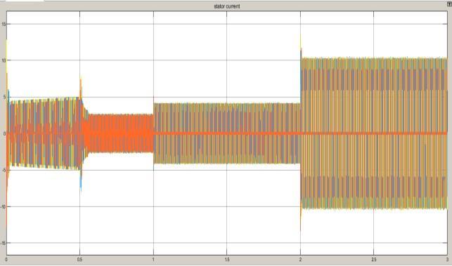
Figure8:StatorCurrentWaveformofBLDCMotor
Figure9,showsthethreephaseinverterlineoutputvoltage waveform.Similartoconverteroutputvoltage,theinverter voltageincreasefrom80Vto250Vatt=0.5sduetoincrease inreferencespeed
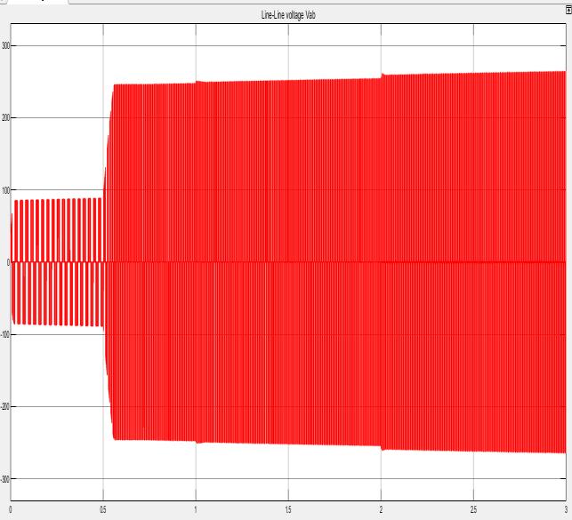
Figure9:InverterPhaseAOutputVoltageWaveform
The system and control parameters used in the hardware modelaregivenintable3.Thehardwaretopologyistested.
Table3:ParametersofthePVbasedLuoconverter CircuitconsideredfortheHardware
0-12V,1A DiodeRectifier S1WB60 BufferIC CD4050UBC Driver TLP250
1N4007
Ω
HARDWARE CIRCUIT
ThehardwarecircuitofPV basedLuoconverterfedBLDC motorisshowninfigure10.230VoltssinglephaseACsupply isprovidedasinputtostep-downtransformerof230/12V, 3A, is then fed to the Positive Output Super-Lift Luo Convertervia rectifier.TheLuoConvertergivesanoutput voltageof36voltsthatisfurtherconnectedtothreephase inverter.Theoutputofthreephaseinverterisconnectedtoa 1000KVBLDCmotor.

International Research Journal of Engineering and Technology (IRJET) e-ISSN: 2395-0056 p-ISSN: 2395-0072
Volume: 11 Issue: 12 | Dec 2024 www.irjet.net
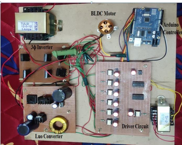
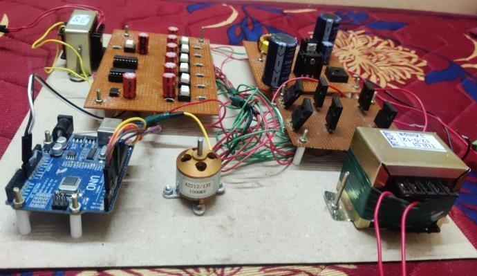
Figure12,showsthegatepulsewaveformgeneratedfromthe driver circuit. The pulse is viewed in the Cathode ray oscilloscope(CRO).
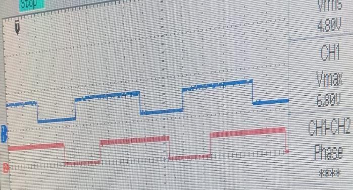
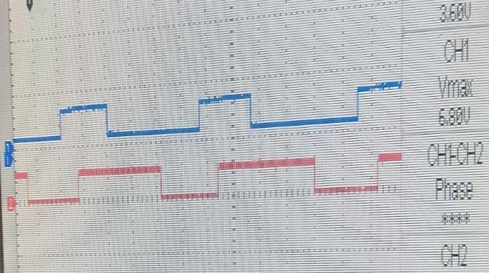
Figure12:GatePulseWaveforms.
Theinputrmsvoltageoftheluoconverterisaround10V,is showninfigure13.
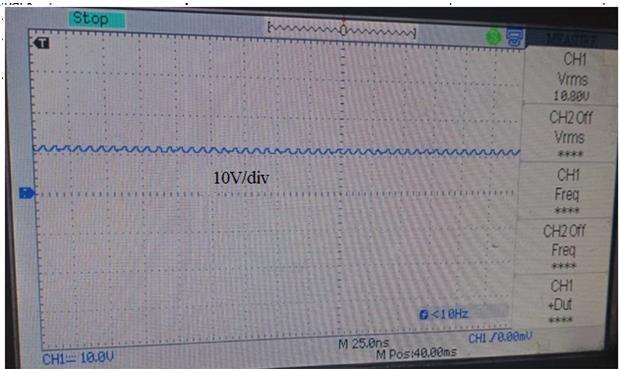
Figure13:LuoConverterInputVoltage
The output voltage of the luo converter is around 34.6 V. Figure14,showstheoutputvoltageoftheLuoconverter.
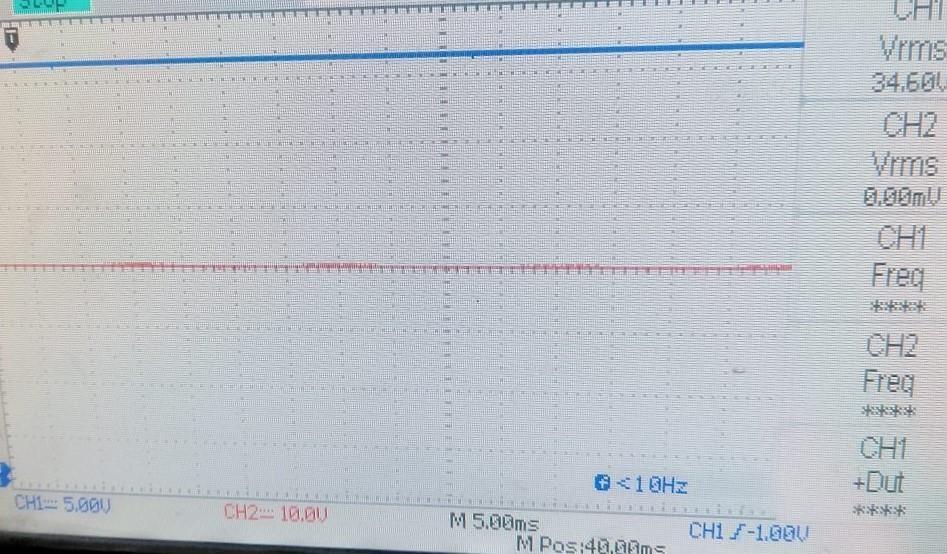
Figure14:LuoConverterOutputVoltageWaveform
Theoutputvoltageofluoconverterisappliedtothreephase inverterandtheoutputvoltagewaveformsofthethreephase inverterisshowninfigure15.
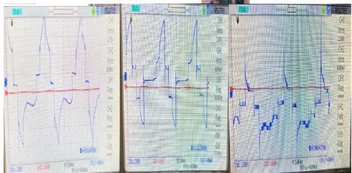
Figure15:InverterVoltageWaveforms

International Research Journal of Engineering and
Volume: 11 Issue: 12 | Dec 2024 www.irjet.net
Inthispaper,designingandimplementationofPVBasedLuo converterFedBLDCMotorwasproposed.ALuoconverter (LC) using Super-Lift Technique is a powerful DC-DC converter where the voltage is converted from positive sourcevoltagetopositiveloadvoltageasitproducespositive voltagesofcomparativelyhigherrangesandproducesless ripples than those of conventional types. The modeling of proposedsystemwascarriedoutonthePVmoduleoftotal capacity of 2100W to obtain improved efficient power extractionandminimalperformanceloss.Thesimulationwas carried out in MATLAB/Simulink software. The hardware prototypeoftheproposedworkfor230Vsingle-phaseAC supplyproducingand36VDCoutputtoruntheBLDCmotor wasimplementedandtheresultswereanalysed.
Fromthesimulationresults,itwasobservedthattheoutput poweroftheLuoconverteris2000Wandhighvoltagegain of240Voltsfrom35.5VoltsPVinputsupplywasobtained. TheBLDCmotorrunsatitsratedspeedirrespectiveofthe loadvariation.Thehardwarewasimplementedforsmaller ratingandwasconnectedtoaBLDCmotorof1000KV.
[1] DeepaM.U.andG.R.Bindu,"Performanceanalysisof BLDC motor drive with power factor correction scheme,"2016 IEEE International Conference on Power Electronics, Drives and Energy Systems (PEDES), Trivandrum,2016,pp.1-5.
[2] Dhanasekar.R,Vaishalee“ImprovedsourceendPower FactorEnhancement ofBLDCmotorusingBridgelessLandsmanconverter”,2018 International Conference On Computation Of Power, Energy, Information And Communication (ICCPEIC).
[3] R.Babu Ashok and B.Mahesh Kumar, “Comparative analysis of BLDC motor for different control topologies,”Energy Procedia 117, pp.314- 320, May. 2017 IEEE International Conference on Engineering and Technology (ICETECH)
[4] S.G.KumarandS.H.Thilagar,"Softsensingofspeedin Load torque estimation for boost converter fed DC motor," IECON 2013 -39th Annual ConferenceoftheIEEE Industrial Electronics Society, Vienna, 2013, pp. 37583763.doi:10.1109/IECON.2013.6699734
[5] Srinivasan, G.K. & Srinivasan, H.T (2013) “ Passivity Based control of Luo converter”. Journal of Electrical Engineering, 13.159-163.
[6] Santosh Kumar Suman, Vinod Kumar Giri “ Speed control of DC motor using optimization techniques based PID Controller”, 2016 IEEE International Conference on Engineering and Technology (ICETECH)
(IRJET) e-ISSN: 2395-0056 p-ISSN: 2395-0072
[7] N.D.MehtaandDr.A.M.Haque,“DesignAndSimulation OfLuoConverterForDcMotorControlForAnElectric VehicleApplications”,InternationalJournalOfApplied Research In Science And Engineering ISSN (Online) : 2456-124X International Conference on Emerging Technologies in Engineering, Biomedical, Medical and Science(ETEBMS–July2017)
[8] Mr.M.Chilambarasan,Dr.M.RameshBabu,Ms.R.Sujatha, DesignAndSimulationofLUOConverterTopologiesFor PhotovoltaicApplications,2014,InternationalJournalof Applied Engineering Research.
[9] PrasannaK,KirubakaranD,RahulkumarJandRudhranJ A, Implementation of Positive Output Super Lift Luo ConverterforPhotoVoltaicSystem,2015, International Research Journal of Engineering and Technology.
[10] BhumikaKS,MadhumithaG,PriyaS,RajeshUppara, Comparative Analysis of LUO Converter with and Without MPPT for PV Applications, 2022, Journal of Mines, Metals and Fuels.
[11]G.C.Sowparnika, A.Sivalingam, M.Thirumarimurugan, FuzzyLogicControlforRenewableSourceDC-DCBoost ConverterusingMATLAB,2015, International Journalof Emerging Technologies in Engineering Reasearch.
[12]S.Subasri,Dr.C.Govindaraju,designandanalysisofluo converterbasedleddriver,2017, International Journal of Electrical and Electronics Research.
[13]Luo,F.L.,andYe,H.:‘AdvancedDC-DCconverters’(CRC Press,BocaRaton,FL,USA,2004)
[14] Anushka Tekade, Rahul Juneja, Manish Kurwale and Prashant Debre, 2016, Design of Super lift Luo Boost ConverterforSolarInverter, InternationalConferenceon EnergyEfficientTechnologiesforSustainability(ICEETS).
[15] Fang Lin Luo and Hong Ye, 2003, Positive output super-lift converters, IEEE Transactions on Power Electronics 18 105-113.
[16]LuoFLandYeH2001Chapter17,DC/DCConversion Techniques and Nine Series Luo- Converters of the Power Electronics, Handbook Edited by Rashid M H, AcademicPress,SanDiego,USA.
[17]So W C, Tse C K, and Lee Y S, 1996, Development of a fuzzy logic controller for DC-DC converters: Design, computersimulation,andexperimentalevaluation, IEEE Transactions on Power Electronics 1124-31.
[18]ChetanP.Ugale,DhumaleRBandDixitVV,2015,DCDCConverterUsingFuzzyLogicController, International Journal of Engineering and Technology 2(4)593-596.
[19]Santhoshi, B.K., Mohanasundaram, K. & Kumar, L.A. ANN-baseddynamiccontrolandenergymanagementof inverter and battery in a grid-tied hybrid renewable powersystemfedthroughswitchedZ-sourceconverter. ElectrEng (2021).

Volume: 11 Issue: 12 | Dec 2024 www.irjet.net
International Research Journal of Engineering and Technology (IRJET) e-ISSN: 2395-0056 p-ISSN: 2395-0072
[20]K.R.Sugavanam,R.SenthilKumar,S.SriKrishnaKumar, S.Karthikumar,V.Tamilmullai,DesignofFLCforOVR Reduction of Negative Output KY Converter, International Journal of Applied Engineering Research (IJAER),2014,Vol:9(24),pp:23689-23699.
[21]KMohanaSundaram,RSenthilKumar,CKrishnakumar, KRSugavanam,FuzzyLogicandFirelyAlgorithmbased HybridSystemforEnergyEfficientOperationofThree PhaseInductionMotorDrives, Indian Journal of Science and Technology,2016, Vol 9(1), DOI: 10.17485 / ijst / 2016/v9i1/85762.
[22]S.G.KumarandS.H.Thilagar,"Softsensingofspeedin Load torque estimation for boost converter fed DC motor," IECON 2013 -39th Annual ConferenceoftheIEEE Industrial Electronics Society, Vienna, 2013, pp. 37583763.doi:10.1109/IECON.2013.6699734