
International Research Journal of Engineering and Technology (IRJET) e-ISSN: 2395-0056
Volume: 11 Issue: 06 | Jun 2024 www.irjet.net p-ISSN: 2395-0072


International Research Journal of Engineering and Technology (IRJET) e-ISSN: 2395-0056
Volume: 11 Issue: 06 | Jun 2024 www.irjet.net p-ISSN: 2395-0072
Rushikesh Shelke1 , Rohit Metkari2, Akash Phuge3
1MBA Student, Advanced Construction Management, NICMAR University, Pune
2MBA Student, Advanced Construction Management, NICMAR University, Pune
3 MBA Student, Advanced Construction Management, NICMAR University, Pune
Abstract - This research paper presents an in-depth case study onthe constructionofcastinsitupilesandpile capsfor PierNumber370atBandraStation,partoftheMumbaiMetro Line 2B project. The study meticulously details the geotechnicalinvestigationprocess,includingboreholedrilling, soil sampling, and in-situ testing to assess subsurface conditionsandinformdesignparameters.Theconstructionof metro infrastructure in urban environments requires meticulous planning and innovative engineering solutions. This paper elaborates on the engineering design considerations for the piles and pile caps, covering concrete mix design and reinforcement detailing. It describes the construction sequence, from site preparation and pile boring to concreting piles and forming pile caps. The use of specialized equipment and techniques, such as rotary piling rigs and tremie pipes for underwater concreting, is also discussed. Findings from this case study provide critical insights into executing large-scale infrastructure projects in densely populated urban areas. The paper concludes with recommendations for future projects, emphasizing thorough planning, continuous monitoring, and adaptive problemsolvingtoachievesuccessfuloutcomesincomplexconstruction environments. This study aims to contribute to the existing body of knowledge in civil engineering and serve as a referenceforpractitionersandresearchersinvolvedinsimilar projects.
Key Words: Cast in Situ Piles, Pile Cap, Geotechnical Investigation, Borehole Drilling, Soil Sampling In-Situ Testing, Metro Infrastructure, Mumbai Metro Line 2B, Pier Number 370, Reinforcement Detailing, Specialized Equipment.
The rapid growth of cities and the need for better infrastructure call for strong and reliable construction methods, especially for large projects like metro systems. The foundation is a crucial part of these projects, as it ensures that the structure remains stable and durable. Amongthedifferentfoundationtechniques,castinsitupiles and pile caps are particularly effective, especially in challengingurbanenvironments.TheMumbaiMetroLine2B projectisasignificantinfrastructureprojectinoneofIndia's mostcrowdedcities.PierNumber370atBandraStationisa
keypartofthisproject,presentinguniquechallengesdueto itscomplexsoilconditionsandurbansetting.Thechoiceof castinsitupilesforthisprojectwasbasedontheirabilityto handleheavyloads,adapttovaryingsoilconditions,andfit within the constraints of the surrounding urban environment.
Building Pier Number 370 came with challenges like controlling groundwater and dealing with varying soil conditionsinabusyurbanarea.Innovativesolutions,suchas dewatering techniques and advanced monitoring systems, wereusedtoaddressthesechallengeseffectively.
1.2
Castinsitupilesaredeepfoundationelementsconstructed directlyattheprojectsite.Thismethodinvolvesdrillinga hole into the ground, placing reinforcement, and filling it withconcrete.Thesepilesareparticularlyuseful inurban environments where soil conditions can vary, and large loadsneedtobesupported.Thiscasestudyexaminestheuse ofcastinsitupilesforPierNumber370atBandraStationas partoftheMumbaiMetroLine2Bproject.
Before construction began, a thorough geotechnical investigationwascarriedouttounderstandthesubsurface conditions.
BoreholeDrilling:Drillingholesintothegroundto collectsoilsamples.
Soil Sampling: Analysing the soil samples in a laboratorytodeterminetheirproperties.
In-SituTesting:Conductingtestson-sitetomeasure soilstrengthandothercharacteristics. These investigations provided crucial data on soil stratigraphy,bearingcapacity,andgroundwaterconditions, whichinformedthedesignofthepiles.
Thedesignofcastinsitupilesinvolvedseveralkey factors:

International Research Journal of Engineering and Technology (IRJET) e-ISSN: 2395-0056
Volume: 11 Issue: 06 | Jun 2024 www.irjet.net p-ISSN: 2395-0072
Load-Bearing Calculations: Determining the load thepilesneedtosupport,includingboththeweight ofthestructureandexternalforces.
Concrete Mix Design: Choosing the right mix of concrete to ensure strength and durability. Reinforcement Detailing: Designing the steel reinforcement within the piles to handle tensile forces. The design aimed to ensure that the piles could support the heavy loads of the metro structure while remaining stable in varying soil conditions.
1. SETTING OUT: From the substructure drawings,a general arrangementdrawingfor pilelayoutshallbeprepared.Inthisdrawing, each pile shall be designated with a specific numbering system with coordinates of pile centreandpilecap.Fromtheprincipalstations (Bench Mark), reference cardinal points of foundationsystemofpilecapsshallbesetout andthesurveypillarsestablished.Toconduct thistechnique,thetotalstationisrequiredand surveyortoperformthis.
2. Utility diversion: A suitable open pit with 2.50m depth to be excavated manually at the borepilelocationtoensurethatnoutilitiesare present to avoid damages. The manual excavationshallbefinalizedinreasonabletime inadvancetoenableutilitydiversionworkto compete withoutadversely affectingthe bore pile works. Any utility encountered shall be diverted prior to drilling in accordance with approvedutilitydiversionplan.Forthisprocess themostimportantpartforanyinfrastructure project is that utility is important with utility you can vary your decision on day by day operationwhethertheworkperformedasper scheduleornot.
3. DRIVING OF TEMPORARY CASING: Rotary drillingrigfittedwithsuitabletool(soilboring tool) to be positioned at the pile point. After necessary checks for verticality of the mast, boringshallbestarted.Oncompletionofboring uptoabout1montop,temporarysteelcasing pipe with suitable length up to 6m will be installedinpositionusingspecialattachmentto therotaryhead.
4. Setting of Piling Rig: Therigiscenteredonthe pilepointandlevelledusingaspiritlevel.Drill to a depth of 2-3 meters with an auger or bucket.DriveatemporaryMScasing(1.2/1.0m diameter,upto6mlong)withahydraulicpress
topreventsoilcollapse.Recordthetoplevelof the casing and ensure vertical piles do not deviate by more than 1.5%, with a location deviationlimitof75mmforgroupedpilesand 50mmforsingleordoublepiles.
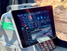

These Two figure showsthe equipment used in pilingworkonsitei.e.SR285R machinewasused forpilingandsecondimageisaboutthescreenthat showsthehowmuch depth till piling isdone and stratafordifferentlayer.
5. Boring of Piles: InitialBoringofabout1.5/2.5 meters shall be done by using auger. The diameterofcuttingtoolshallbelesserthanthe outsidediameterofcasingminus75mm.Piles shallbedonebyusingtemporarycasingupto weathered basalt. As per the Sub-Soil Investigationreport(Attached)certifiedbythe agency non cohesive collapsible strata/sandy strataisnotpresent.Therefore,bentoniteshall notuseforboring
6. BENTONITE: But in case of collapse of borehole bentonite slurry shall be used (if required)forboring&flushingofborehole.
7. REINFORCEMENT CAGE LOWERING: Thebar bendingschedulebasedonapproveddrawing isprepared.Reinforcement iscutand bent to requiredsizeandshape.Specifiedcoverblocks shallbeprovidedtoreinforcementcageforthe pile.Reinforcementcageshallbeloweredin2 pieces or more depending on the available length of steel bars & length of pile. Bottom cage is lowered inside the borehole and temporarilysupportedonthecasingpipetop, keepingthedowellengthprojectingaboveand secondcageisliftedandlappedasperapprove drawings or construction drawings. Helical / rings are tied as per approved drawing and main reinforcement laps are tack welded to provide more rigidity to the cage. The cageis furtherloweredintheborehole.Alternatively, both the cages will be lapped & welded on ground&theentirecagewillbeloweredinside the bore. The reinforcement shall project 60 timesbardiametersabovethecutofflevel.

International Research Journal of Engineering and Technology (IRJET) e-ISSN: 2395-0056
Volume: 11 Issue: 06 | Jun 2024 www.irjet.net p-ISSN: 2395-0072
8. SONIC TUBE: Pilemustbeprovidedwith4no’s sonicloggingtubeswhicharerequiredtoverify thestructuralintegrityofpilesbymeansofthe measurement of the time travel of a sound wavefromemittertoreceiverthroughconcrete ofpile.Thesonictubeshallbemadeupofsteel having 1mm thickness and 50mm inner diameter.
9. CONCRETING: After cleaning the bore hole, attachafunneltotheTremiepipeforconcrete pouring, which must be done within 6 hours. Ensure the concrete temperature meets specifications. Pour the concrete through the Tremie, keeping the pipe 300 mm above the borebottomandembeddedinconcreteby1.0 to1.5meters.Afterconcretingtotherequired level,withdrawthetemporarycasingandmove the rig to the next pile. Check the concrete's workability, and prepare and test concrete cubesfor7and28-daystrength.Onceallpiles arecastandweakconcreteisremoved,submit a drawing showing the exact pile locations relativetothecolumncenterline.
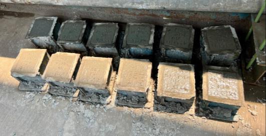
Fig -2:Concretecubefortesting
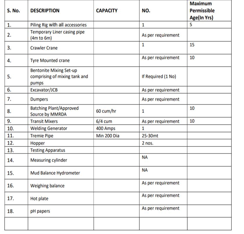
CONSTRUCTION EQUIPMENT: Thesearelistofequipment requiredforcastinsitupileasfollowing.
Thistableshowstherequirementofequipmentforcastin situpileforconstructionworkwiththeirnumberrequired on site. This data is taken from directly report of detailed progressreportofprojectthatisestimatingthatitrequires thismuchrequirementequipment.
Table -1:Equipmentrequiredforcastinsitupile.
3 PILE CAP:
Pile caps are essential components in deep foundation systems,servingasthecriticallinkbetweenthepilesandthe superstructure they support. They play a vital role in distributingloadsevenlyacrossthepilesandensuringthe structuralintegrityofthefoundation.Inthecontextofurban infrastructureprojectsliketheMumbaiMetroLine2B,pile caps are particularly important due to the high loads and complexsoilconditionsencountered.
3.1 Purpose and Function of Pile Caps:
Theprimaryfunctionofapilecapistotransferloadsfrom thesuperstructure,suchasbridgesorbuildings,tothepiles below. This load transfer is crucial for maintaining the stabilityandperformanceofthestructure.Pilecapalsohelps to distribute load evenly on all over the place. And also it enhancesthestructuralstabilitytoprovidesolidfoundation andreducesthesettlementinsoil.
3.2 Utility Problems in the Construction of Pile Cap:
The construction of pile caps, particularly in urban environments, can encounter various utility-related challenges. These challenges arise due to the presence of existing underground and above-ground utilities, such as water lines, sewage systems, electrical cables, and communication networks. Addressing these challenges effectively is crucial to ensuring the smooth progress of construction and the safety of both workers and the surroundingcommunity.Thissectionoutlinesthecommon

International Research Journal of Engineering and Technology (IRJET) e-ISSN: 2395-0056
Volume: 11 Issue: 06 | Jun 2024 www.irjet.net p-ISSN: 2395-0072
utilityproblemsencounteredduringtheconstructionofpile capsandthestrategiesusedtomanagethem.
3.3
1. Identification of Existing Utilities: One of the initial challenges in the construction of pile caps is accurately identifyingthelocationandtypeofexistingutilities.Failure todosocanleadtoaccidentaldamage,servicedisruptions, andincreasedprojectcosts.
Solution: Conduct comprehensive utility surveys using techniques such as Ground Penetrating Radar (GPR), electromagnetic detection, and potholing. These surveys helpcreateaccuratemapsofundergroundutilities.
2.Managing Unexpected Utility Encounters:
Despite thorough planning, unexpected utility encounters can occur during construction, leading to delays and additionalcosts
Solution: Establish contingency plans for managing unexpectedutilityencounters.Thisincludeshavingstandby crewsandequipmentreadyforimmediateresponse,aswell as maintaining open lines of communication with utility providers.
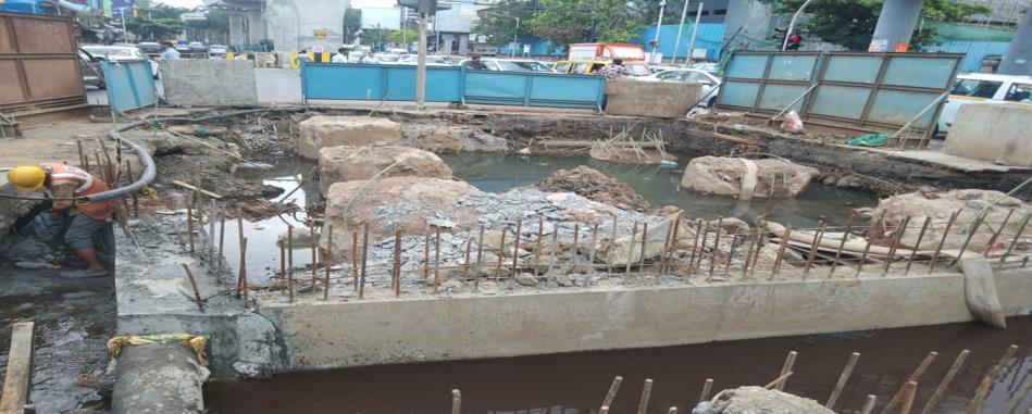
So,thisisthecasewhileweareworkingonsitetheutility problemarisethatwatercomesfromthedrainagelinedue chokingorfailureofdrainagelinesotocounterthisweneed tosatisfyallthestakeholdersfirstandmakeawayforthe drainagewaterbycreatingdiversiontheline.Ittakeslotsof timebecauseofunexpectedutilityencounters.
Thisfigureshowsthatwhileworkingonthepilecap,autility problem arose due to a damaged drainage pipeline. To resolve this, a diversion slab was created to redirect the waterflow,allowingtheremainingwatertobepumpedout from the site. Such utility problems are common in infrastructureprojectslikemetrobridges.Toaddressthis situation, all stakeholders came together, including the senior site engineer, the deputy project manager, and the
project manager. Additionally, representatives from the client side, MMRDA, and government bodies such as BMC andMCGMwereinvolved.
Preparation and Layout: Clearthesiteandsetout thepilecapdimensionsasperthedesign.Ensureall necessary materials and equipment are available on-site.
Excavation: Excavate the area to the required depth and dimensions of the pile cap. Maintain stableexcavationsideswithshoringifneeded.
Pile Head Preparation: Trim the piles to the correctlevel,ensuringtheyarecleanandfreefrom debris.Exposethepilereinforcementtoallowfor properbondingwiththepilecapreinforcement.
Formwork Installation: Erect formwork around the excavationtocreatethe shapeofthepilecap. Ensuretheformworkissecureandwell-supported toholdtheweightoftheconcrete.
Reinforcement Placement: Place reinforcement bars as per the design specifications, ensuring proper spacing and alignment.Tiethereinforcementbarssecurelyand ensure they are positioned correctly within the formwork.
Concrete Pouring: Pour concrete into the formwork, ensuring it is evenly distributed and properlycompacted.Usevibratorstoeliminateair pockets and ensure good bonding with the pile reinforcement.
Curing: Curetheconcreteproperlytoachievethe requiredstrength.Maintainthecuringprocessfor the specified duration, typically using water or curingcompounds.
Formwork Removal: Oncetheconcretehasgained sufficientstrength,removetheformworkcarefully. Inspectthepilecapforanydefectsorirregularities andmakenecessaryrepairs.
Finishing: Applyfinishingtouchestotheexposed surfacesofthepilecap.Ensurethepilecapisclean andreadyforthenextstageofconstruction.
4.
These results are based on the different parameter of the primary objective of this study was to analyse the constructionandperformanceofcastinsitupilesandpile capsforMetroLine2BinMumbai,withaspecificfocuson PierNumber370atBandraStation.Theresultspresented hereinprovideinsightsintothestructuralintegrityandloadbearing capacities of these components, contributing valuabledatatothefieldofmetrobridgeconstruction.
1. GEOTECHNICAL INVESTIGATION: Thegeotechnical investigationfortheconstructionofcastinsitupiles

International Research Journal of Engineering and Technology (IRJET) e-ISSN: 2395-0056
Volume: 11 Issue: 06 | Jun 2024 www.irjet.net p-ISSN: 2395-0072
iscrucialforunderstandingthesubsurfaceconditions, whichdirectlyinfluencethedesignandexecutionof the piling work. This report presents a detailed analysis of borehole data obtained from the construction site at Bandra Station for pier number 370. The borehole details include soil stratification, groundwaterlevels,andtheengineeringpropertiesof each soil layer. These data are used to calculate the bearingcapacityandsettlementcharacteristicsofthe piles. The borehole investigation involved drilling multipleboreholesatstrategiclocationsaroundthe site. Each borehole was logged to document the varioussoillayersencountered.Thefollowingtable summarizesthekeydetailsfromtheboreholelogs:
Table -2: Soilinvestigationdetails
Preparation of soil report
Calculation of Bearing Capacity:
Thebearingcapacityofthepileisdeterminedusingthesoil propertiesobtainedfromtheboreholelogs.Thecalculation isperformedforeachlayerencountered,usingthefollowing equationforultimatebearingcapacity(Qu):
Qu= qf = c'Nc + γDNγ + 0.5γBNγ cisthecohesionofthesoil.
σistheeffectiveoverburdenpressure.
γistheunitweightofthesoil.
Bisthewidthordiameterofthepile.
����, ����, ����N c, N q, N γ are bearing capacity factors dependentonthesurfacefrictionangle
Now calculate one value from table for ultimate bearing capacityforBH-01atdepthof9-14meterhavingc=15
Wecancalculatefromthistheoreticalformulaalsobutaswe workonsitetheformulatetocalculatethebearingcapacity isrequiredasfollowing
Step 1: End Bearing Capacity (Qb)
Theendbearingcapacityforapileincohesivesoilisgiven by:
Qb=Ap×c×Nc
Calculate the cross-sectional area of the pile base (Ap): Ap=π/4×d2=π/4×(1.2)2=1.131m
Calculate the end bearing capacity (Qb): Qb=1.131m2×15kN/m2×9=152.685kN
Step 2: Skin Friction (Qs):
Qs=Perimeterofpile×Length×c×α perimeterofpile=π×d
Length=5meters(from9mto14m)
αistheadhesionfactor,typicallyaround0.7forcohesive soils.
Calculate the perimeter of the pile: π×d=π×1.2≈3.77m
Calculate the skin friction (Qs): 3.77m×5m×15kN/m2×0.7=198.225kN
Step 3: Total Ultimate Bearing Capacity (Qu):
Thetotalultimatebearingcapacityisthesumofthe endbearingcapacityandtheskin friction:
Qu=Qb+Qs=152.685kN+198.225kN=350.91kN
Summary :
End Bearing Capacity (Qb):152.685kN
Skin Friction (Qs):198.225kN
Total Ultimate Bearing Capacity (Qu):350.91kN
Thus,theultimatebearingcapacityofthepileforthegiven parametersisapproximately 350.91 kN
Theultimatebearingcapacityofthepile,combiningtheend bearingcapacityof152.685kNandskinfrictionof198.225 kN,resultsinatotalofapproximately350.91kN.Thisvalue indicates the maximum load the pile can support before failure.

International Research Journal of Engineering and Technology (IRJET) e-ISSN: 2395-0056
Volume: 11 Issue: 06 | Jun 2024 www.irjet.net p-ISSN: 2395-0072
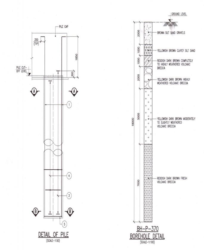
This figure shows about the borehole detail of soil at differentstratafromweexecutethepileworkonsite.
2. Load Combinations in Cast in Situ Piles:
Thestructuralintegrityandsafetyofcastinsitupiles arecriticallydependentontheaccurateassessment andapplicationofvariousloadcombinations.These loadcombinationsareessentialforensuringthatthe piles can withstand the different forces they will encounterduringtheirservicelife.Theprimaryload combinationsconsideredforcastinsitupilesinclude deadload,liveload,windload,seismicload,andany additionalenvironmentaloraccidentalloads.
Load Calculations
DeadLoad(DL):Weightofthestructureitself.
����=Volumeofconcrete×Densityofconcrete
DL=Volumeofconcrete×Densityofconcrete
Forapileofdiameter��=1.2�� d=1.2mandlength��=18��L=18m, Volume=��(��2)2��=��(1.22)2×30=33.93��
LiveLoad(LL):Imposedloadfromtrafficand utilities.
��=DesignvalueasperIRCspecifications
LL=DesignvalueasperIRCspecifications
Assuminganestimatedliveloadof500kN,
UltimateLoad(UL):����=1.5×(����+����)=1.5× (848.25����+500����)=2022.375����
UL=1.5×(DL+LL=1.5×(848.25kN+500kN) =2022.375kN
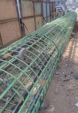
1. Reinforcement Calculation to calculate Bars: Bar bending schedules (BBS) are critical in the construction of reinforced concrete structures, ensuringthatreinforcementbarsareaccurately fabricated and placed according to design specifications. In cast in situ piles, vertical bars provide essential support against compressive and tensile forces, contributing to the pile’s overallstabilityandload-bearingcapacity.This section provides a detailed calculation of bar bending for vertical bars, demonstrating the processthroughasamplecalculation.
Sample Calculation: Vertical Bar Bending in Cast In Situ Pile
Given Data:
Diameter of vertical bar (D) = 20 mm
Length of pile (L) = 14 meters
Concrete cover = 75 mm
Number of vertical bars = 16
Length of pile = 1.585m
Lap Length =63D
Dia of Pile - 1200mm
Calculation Steps:
Step 1: Determine the Length of One Vertical Bar:
cutting length of bar = Lsection+lengthofpile uptocutofflevel+lengthofpilecap+laplength -(cover+bend+bar)
=250+15850+1850+1260-(75+75+(2x 20)+40)=18,980mm =18.98m
Step 2: Calculate the Total Length of Vertical Bars Required: =18.980x16=303.68m
Step 3: Weight of Steel Required: weight of bar = d^2/162=2.46kg, fortotalbar=46.86kg for16bar=750kg
This sample calculation outlines the process of determining the length and weight of vertical bars needed for a cast in situ pile, ensuring precisioninbarbendingschedulesandoptimal materialusage.
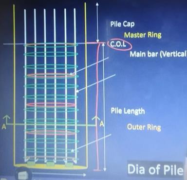
Also, there are three kinds of majorly bar required for calculation of pile in bar bending schedule such as master ring, outer ring and verticalmainbar.

International Research Journal of Engineering and Technology (IRJET) e-ISSN: 2395-0056
Volume: 11 Issue: 06 | Jun 2024 www.irjet.net p-ISSN: 2395-0072
2.Concrete Mix Design: Theconcretemixdesignisa criticalaspectofconstructingcastinsitupiles,as it determines the durability, strength, and workabilityoftheconcreteused.Forpiernumber 370 at Bandra Station, the mix design process involvedmeticulousplanningtomeetthespecific requirementsofthesiteconditionsandstructural demands. The mix design for M35 Grade Of Concreteforpilefoundationsprovidedhereisfor reference purpose only. Actual site conditions varyandthusthisshouldbeadjustedasperthe locationandotherfactors.Thefollowingoutline process and calculations involved in designing theconcretemixforthisproject:
GradeofConcrete:M35
CharacteristicStrength(Fck):35Mpa
TestDataforMaterial:
AggregateType:Crushed
SpecificGravity
Cement:3.15
CoarseAggregate:2.67
FineAggregate:2.62
WaterAbsorption:
CoarseAggregate:0.5%
FineAggregate:1.0%
MIXDESIGN
Take Sand content as percentage of total aggregates=36%
Select Water Cement Ratio = 0.43 for concrete gradeM35
SelectWaterContent=172Kg
Hence,CementContent=172/0.43=400Kg/ M3
M35 mix design ratio: Mixture of cement: sand: aggregate - 1:1.6:2.907
PILE CAP CALCULATION: The pile cap is a critical structural element in the foundation system of metro elevated bridges, designed to distribute loads from the superstructure to the pilesembeddedintheground.FortheMetroLine 2BprojectinMumbai,thecalculationofthepile cap involves determining the appropriate dimensions and reinforcement to ensure adequate load transfer and structural integrity.
Accurate calculation of the pile cap dimensions and reinforcement is essential for ensuring the stability and durability of the structure.
PILE CHIPPING IN PILE CAP:
Pilechippingisavitalpost-constructionprocess forcastinsitupiles,ensuringasmoothsurface forpilecapsandproperpilealignment.Forthe MetroLine2BprojectinMumbai,theprocedure beginswithsiteinspectionandmarkingthecutoff level on the pile head. Using pneumatic or hydraulicchippinghammers,excessconcreteis graduallychippedawaytothemarkedlevel.The pile head surface is then finished smoothly. Throughout the process, strict safety protocols and quality control measures are maintained, includinginspectionsandnon-destructivetesting to ensure the integrity and dimensions of the chipped pile head. This systematic approach ensures the pile's readiness for subsequent structuralelements.
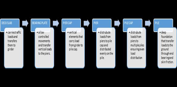
Thisdiagramshowsabouttheloadtransferpathsummary mechanism of elevated bridge and from this we can understandabouttheloadtransferoffcomponents.
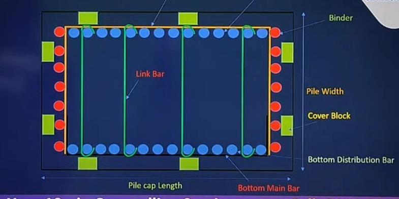
CALCULATION OF REINFORCEMENT OF PILE CAP:
Tocalculatethis,weneedtoknowaboutthegivendataso thatwecancalculatethecuttinglengthofrequiredforpile cap.Beforethatincalculationofreinforcementofpilecap thatisbarbendingscheduletherequiredbaris
Distributionbar
Binderbar
Linkbar
Mainbar
STEP 1) given data:
pilecapsize:7700x5700x2000mm
clearcover:75mm
spacing:150mm
bottomreinforcementbar25mm
diameterofbinderbar16mm

International Research Journal of Engineering and Technology (IRJET) e-ISSN: 2395-0056
Volume: 11 Issue: 06 | Jun 2024 www.irjet.net p-ISSN: 2395-0072
Nowwecalculateonebottommainbarforpilecapfromthe drawinggivendataasfollows:
Calculate Cutting length: width of pile cap+2(length of l)(cover+bend+bar)
=5700+2x(300)(2x75+2x2x25+2x16) =6018mm
Number of bar= Effective length of pile cap/spacing+1 Effectivelengthofpilecap=Pilelength-(2xcover+2xbinder) =7700-(2x75+2x16) =7518mm
Numberofbar=7518/150+1=51.12
STEP 2) Weight of steel required: D^2/162 =25x25/162 =3.858kg
Total weight of steel required at length= weight of steel x cutting length of bar x no. of bar =3.858x7518x51.12 =1482.706kg
Thiscalculationisbasedondrawingandonlywecalculate forbottommainbarreinforcementforpaperpurposeonly.
Result and Discussion Interpretation:
Theintegrationofgeotechnicaldata,precisereinforcement detailing,optimizedconcretemixdesign,andthoroughload analysiscreatedastrongfoundationsystemfortheMetro Line2Bproject.Geotechnicalinvestigationguidedpiledepth andplacement,ensuringproperload-bearingcapacity.The reinforcementBBSmaintainedstructuralintegrityandmet design standards. The concrete mix design provided the necessary strength and durability. Comprehensive load analysisensuredthefoundationcouldhandledifferentload conditions,guaranteeingsafetyandstability.Thisapproach showshowcombiningdetailedengineeringpracticesleads toareliableanddurablefoundationsystem
Thisresearchpaperdetailedtheconstructionofcastinsitu pilesandpilecapsforPierNumber370atBandraStation, partofMumbaiMetroLine2B.Itcoveredthegeotechnical investigation process, including borehole drilling and soil sampling,whichinformedthedesignparameters.Thepaper describedtheconcretemixdesign,reinforcementdetailing, andconstructionsequence,fromsitepreparationandpile boring to concreting and pile cap formation. Advanced equipment like rotary piling rigs and tremie pipes for underwater concreting were essential for overcoming construction challenges. The study highlighted the importance of thorough planning, continuous monitoring, and adaptive problem-solving in urban infrastructure projects.Thesefindingsprovidevaluableinsightsforfuture projects and contribute to the body of knowledge in civil engineering.
[1] IS Code 456:2000 Code of practice for plain and reinforcedconcrete.
[2] IS 1892:1979 – Code of practice for subsurface investigationforfoundations.
[3] liu-et-al-2014-optimization-study-on-blasting-schemeof-metro-stations-subsurface-excavating-obliquethrough-pile.
[4] IS 2911 (Part 1/Sec 2):2010 – Code of practice for designandconstructionofpilefoundations-Boredcast insitupiles
[5] Vol. 3, Issue 2, pp: (74-80), Month: October 2016 –March2017,Availableat: www.paperpublications.org PileFoundationAssociatedtoMetroRailHyderabad
[6] Use of large-diameter, cast–in situ concrete pipe piles forembankmentoversoftclay(cdnsciencepub.com)Use of large-diameter, cast–in situ concrete pipe piles for embankmentoversoftclay
[7] Construction Technique of Pile-Board Subgrade Crossing Over-Shallow-Embedded Metro in Deep Soft Ground
[8] Wada, Akira, "Skin Friction and Pile Design" (2004). International Conference on Case Histories in GeotechnicalEngineering.14.SKINFRICTIONANDPILE DESIGN
[9] Comparative_evaluation_of_load_bearing_capacity_of_bo red_piles_using_numerical_approach_empirical_co_relations
[10] DetailedProgressReportforLine2bmetro

International Research Journal of Engineering and Technology (IRJET) e-ISSN: 2395-0056
Volume: 11 Issue: 06 | Jun 2024 www.irjet.net p-ISSN: 2395-0072
[11] ConcreteMixDesignNeville,A.M.,&Brooks,J.J.(2010).
[12] Exercisefordesignofcast-in siturcpile.
[13] AlldataistakingfromDrawing.
BIOGRAPHIES


I am currently pursuing MBA, in
Advanced Construction Management and my area of interestisinprojectplanningand controlling.
I am currently pursuing MBA, in Advanced Construction Management and I have already published two research paper on IRJET.
I am currently pursuing MBA in Advanced Construction Management student at NICMAR, specializingin industry-standard software and have hands-on experience through internships andprojects
2024, IRJET | Impact Factor value: 8.226 | ISO 9001:2008