
International Research Journal of Engineering and Technology (IRJET) e-ISSN: 2395-0056
Volume: 11 Issue: 06 | June 2024 www.irjet.net p-ISSN: 2395-0072

International Research Journal of Engineering and Technology (IRJET) e-ISSN: 2395-0056
Volume: 11 Issue: 06 | June 2024 www.irjet.net p-ISSN: 2395-0072
Harshitha
.S1 ,
Jegidha
K.J2 ,
Kathir
vel3 ,
1 PG student, Dept. of Civil Engineering, ADHIYAMAAN College of Engineering Hosur, India
2 Assistant professor, Dept. of Civil Engineering, ADHIYAMAAN College of Engineering Hosur, India
3 Assistant professor, Dept. of Civil Engineering, ADHIYAMAAN College of Engineering Hosur, India ***
Abstract - This paper aims to review the strengthening techniques of Reinforced Concrete (RC) beams using steel jacket. The structural elements with poor strength and low bearing capacity are due to seismic activity, aging, temperature conditions, and attack of fire. To restore the strength as well as the age of the entire structure, retrofitting video wrapping or jacketing technique is used. Nowadays, retrofitting is widely used in the world. The present study focuses on the performance of galvanized-iron wire mesh(GI) in the rectangular reinforced column of the weaker section which delays the crack patterns andbucklingeffectaslifespan increases with the three incremental intervalsof25%foreach of the four columns. Further,comparingthehigherpercentage mesh mesh-wrapped columns with the lower percentage wrapped ones.
Key Words: Retrofitting, Galvanized iron wire mesh, jacketing technique, strength.
1. INTRODUCTION
Column is the major element which carries compressive loadsofthesuperstructuretothesubstructure.Thefailure of the column leads to destruction or performance is comparatively very low. Generally, failure occurs due to overloading, weaker cross-sectional area, dynamic loads, elasticinstability,Seismicactivity,fire,corrodedsteel,etc... Toregainthestrengthofdamaged/deficientcolumnscanbe rehabilitatedbyretrofittingtechnique.Jacketingisoneofthe most occurring and economical methods of retrofitting techniques in major projects. Steel Jacket, Reinforced Concrete Jacket, Fibre Reinforced and Polymer Composite are few types of Jacketing. The steel jacketing method consistsofGalvanizedIron(GI)wiremeshthatimprovesthe ductility,compressionstrength,andgoodconfinementtothe column.
Muhammad N. S. Hadi et al (2011) investigated various materials such as fiberglass wire mesh (FGFM), standard aluminumflymesh(SAFM),andGalvanizedsteelwiremesh of12.7*12.7mmsize(S12.7WM).Totalsixteennumbersof circular columns were loaded under eccentric, concentric,
andpurebendingloading.Thisstudyshowsanincreasein bothstrengthand ductility ofcompression members with additionofthesematerials.Amongallspecimens,highloadcarryingcapacitywasincreasedbywiremeshandductility wasimprovedbyFGFM.
AzamAmiretal.mentionedabouttheGIWireMeshearlier in2013.ThisstudydealswiththecombinationofFRPand WireMeshappliedatcriticalsectionstostabilizetheexisting building columns of three no's with greater seismic resistanceandstrength.FRPsheetswereusedforhorizontal wrapsinthefirststrengtheningschemeandwiremeshin the2ndstrengtheningscheme.Amongthese,highstrength wasachievedbyFRPsheet,andductilitywasincreaseddue to FRP and wire mesh. FRP jacketing can be adopted for strengtheningpurposesinfurtherretrofittingprojects.
Amrul Kaish et al (2013) researched improving square jacketingtechnique(SJT)torestorethestrengthofexisting RCcolumns.Introducingtwoschemesinthisstudytoreduce theconcentrationofstressandcracksatcornersi.e.,(i)all corners were to be strengthened and (ii) reducing corner stresses.AtotaleightnumbersofsquareRCcolumnswere loadedunderconcentriccompressiveloadinguntilfailure. Amongeightnumbers,sixnumbersareretrofittedonesand theremainingtwoareofcontrolspecimens.Threetypesof jacketingtechniqueswereusedsuchas(a)Withtheaddition ofwiremeshofasinglelayer,(b)Withtheadditionofone layerofwiremeshandthecornersofcolumnarerounded, and(c)Withtheadditionofsinglelayerandtwomoreextra layersatallcornersofthecolumn.
Bishnu Gupt et al (2014)conducted tests on nine columns withtwotypesofretrofittingmethods,theyarewiremesh mortar jacketing (WMM) and steel cage mortar jacketing (SCM) of three specimens each are compared with plain reinforcedcolumns(CS).Variationsinresultsincomparison withWMMandSCMare1.75and2.28timesgreaterthanCS. WMM got the higher Stiffness value as compared to CS. According to strength consideration SCM is preferred and WMMinabsorptionconsideration.
Manikandeswaran et al (2015) have done experimental work on nine RC columns with two types of jacketing techniques; the Ferro cement technique and steel angles
International Research Journal of Engineering and Technology (IRJET) e-ISSN: 2395-0056
Volume: 11 Issue: 06 | June 2024 www.irjet.net p-ISSN: 2395-0072
withstrips.Thisstudyisaimedtoachievehighload-bearing capacityascomparedtoRCcolumns.Basedonthisstudy,it wasconcludedthatsteelangleswithstripsimprovedloadbearing capacity by 40% and Ferro cement technique by 65%incomparisontoRCcolumn.
MuhammedSalihetal(2016)conductedexperimentalwork on Ferro cement confinement in four numbers of square columnswithlowstrengthalongwiththeadditionof0.1%of polypropylenefibersinmortarmix.Beforeretrofittingusing Ferro cement jacketing technique, columns were loaded underultimateload.Thereisanincreaseintheload-carrying capacity of these retrofitted columns in comparison to controlspecimensandnospallingofconcretecover.
3.1
Cement
OrdinaryPortlandcementof53Gradeswasusedforthe casting of rectangular reinforced concretecolumns and wire mesh confinement in the experimental work. The specificgravityofcementis3.15.
Coarse Aggregate
Acoarseaggregateof20mminsizeandaspecificgravityis 2.884wasusedintheexperimentalwork.
Fine Aggregate
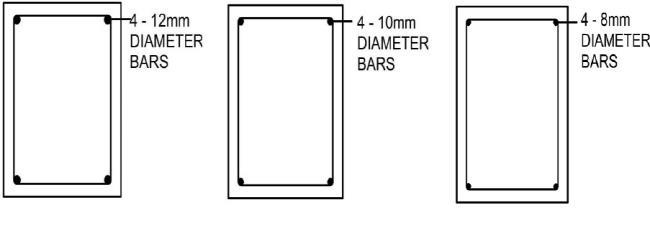
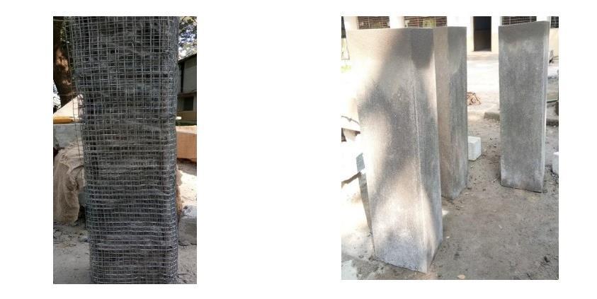
FineAggregatebelongstozoneIIanditsspecificgravityis 2.6wasusedinthisstudy.GI Wire Mesh
ThediameteroftheGalvanizedIronwiremeshwas1.3mm withspacingof15mmX15mmspacing.
3.2 Mix Proportion
Mix was designed as per the specifications of IS: 102621982togainatargetstrengthof31.6N/mm2.Accordingto thedesigncalculations,thecementcontentwas438kg/m3 . Thewater-cementratiotakenfromthedesignwas0.45.
Table 1 Mix propotion
3.3 Casting of RC columns
Four rectangular reinforced concrete columns havingacross-sectionalareaof230x300mm2andlengthof
1000mmwerecastalongwithconsiderationof1%ofsteel in design. Among all the four specimens, one is of control specimen(CS)andtheotherthreeareretrofittedspecimens (RS). 4 –12mm Ø and 4 –8mm Ø longitudinal rebar and stirrups of 8mm diameter lateral ties @ 192mm c/c was used in the control specimen. The other three specimens wereprovidedwithlesslongitudinalreinforcementdetails suchas12mm,10mm,and8mmrebarswereshownbelow inFigure1andFigure2.
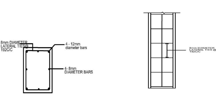
1ReinforcementDetailingoftheControlSpecimen
3
Figure2DetailingofRetrofittedSpecimens
GI wire mesh was used in the steel jacketing techniquewithvariouspercentagesof25%,50%,and75% ofwiremeshbyreducinglongitudinalreinforcementdetails. Differentsizesofrebarwereusedsuchas12,10,and8mm diameters in each specimen as per design considerations. Afterthedurationofthe28-daycuringperiod,a20mmclear coverwaschippedbychippinghammer,andthen3,3.5,and 4 numbers of layers of wire mesh were wrapped with no gapsinbetweenthelayersaroundthesurfaceofthechipped areaofthespecimen.Tomakethemeshfirmitwastiedto the longitudinal reinforcement with bending wires. Plasteringwasdoneforthemeshedcolumnswitharatioof 1:2 as per the considerations. Duration of curing for retrofittedspecimenswas28days.
International Research Journal of Engineering and Technology (IRJET) e-ISSN: 2395-0056
Volume: 11 Issue: 06 | June 2024 www.irjet.net p-ISSN: 2395-0072
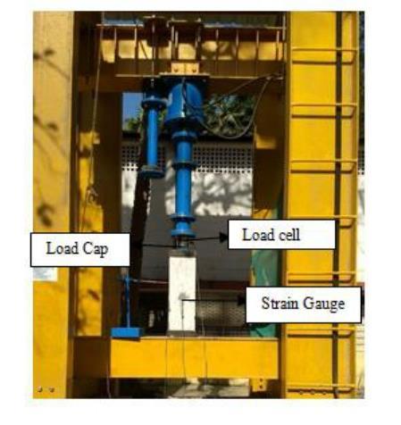
3.5 Testing Procedure
Thecolumnwasplacedsuchthatpositioningofthe loadcelloftheloadingframeisexactlytothecenterofthe topsurfaceofthecolumn.Twosteelcapswereprovidedat thetopandbottomendsofthecolumnsothattheyrestrict the spalling of the concrete during loading. Two Strain gaugeswereplacedeitherinverticalorhorizontalpositions at the center on any of the two sides. Gauge wire and connectorwiresoftheframeweresolderedandkeepthem inanundisturbedpositionandLVDTwasarrangedcarefully. Theprobeoftheloadingframewasconnectedtotheload cell. The loading frame with the test setup was shown in Figure5.
4. RESULTS AND DISCUSSIONS
Themaximumloadcarriedbythespecimensand theirdeflectionswerenotedinbelowtable1.
Table2LoadandDeflectionofeachmember
Maximum and minimum loads carried by RS2 and RS1.Confinementof50%hasmorestrengththanthatof25% confinement.
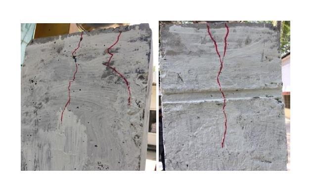
The control specimen was axially loaded and readings of eachsecondwererecorded.Asperdesign,theultimateload is 960.342KN. The maximum load-bearing capacity of the memberis1008.2KN.Initialcrackinghavebeenstartedat theloadof994.5KNatthetopend atadepthof300mm vertically.Theconcentrationofstresswasmoreatthe toptheendofthecolumn.Slightspallinghasoccurred atthetopsurfaceoftheconcretemember.Thecrack patterncanbeobservedinFigure6.
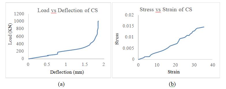
FromFigure.7(a)itwasshownthattheminimumdeflection ofthecolumnis0.35mmataloadof58.8KN.Thedeflection in between loads of 86.1KN to 92.2KN and 128.1KN to 179.7KN were relatively the same and later there was a gradual increase along with the load. The maximum deflectionoccurredattheloadof1008.2KNis1.85mm.
Fromthefigure.7(b)showsthevariationsbetweenstress andstrain,Initialstrainoccurredat0.000852KN/mm2.Then thereisanincreaseinstrainforaboutavariationof3.5to6 at constant stress and is gradually increased up to the maximumof35.5at0.014611KN/mm2 .
International Research Journal of Engineering and Technology (IRJET) e-ISSN: 2395-0056
Volume: 11 Issue: 06 | June 2024 www.irjet.net p-ISSN: 2395-0072
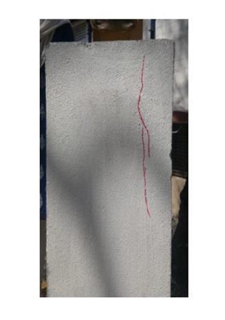
RS1wasprovidedwitha25%areaofwiremeshwhichwas axiallyloadedupto1096.9KN.Crackswereformedfromthe topend.Initialcrackingstartedattheloadof1044.5KN.This wasmoreductilethanthecontrolspecimenasthereisless impactofstressandhighload-bearingcapacityandalsoage of the structural member was increased. Restrengthening extendsthefailureperiodbyprovidingmeshrefinementto thismember.
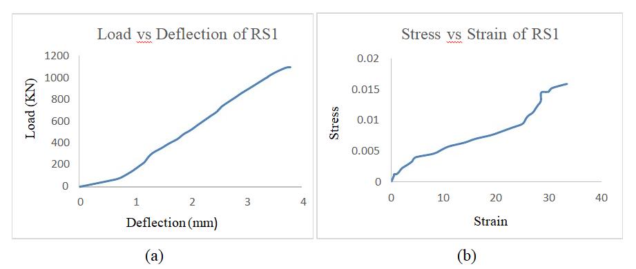
In the figure. 9(a), the load and deflection curve of the retrofittedspecimen-1havebeenshown.Fromthegraph,it isseenthatthedeflectioncurvehasbeenincreasedwithan increase of load linearly up to the ultimate load of the specimen.Theminimumdeflectionofthespecimenoccurred at0.67mmandisconstantforaloadof70.3KN.
The stress-strain curve for the retrofitted specimen1 is showninfigure.9(b).Theinitialstrainisoccurredatastress of0.001018KN/mm2.Thecurveislinearlyincreasedwithan
increase in stress of 0.009389KN/mm2 and suddenly increaseduptothestrainof33.5.
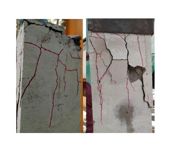
RS2 was provided with 50% of wire mesh with reduced longitudinalreinforcement.Stressconcentrationwashigher inthetopsectionascrackswerepassedtowardsthecenter due to repeated loadings. The behavior of the specimen duringtheloadingswasabouttobuckleasitexceededits compressivestrengthandthememberalmostenteredthe buckling stage. Comparatively, this refinement gave good strength and high bearing capacity as compared to the controlspecimenandRetrofittedspecimen1.
In the figure. 11(a), the load-deflection of retrofitted specimen-2havebeenshown.Deflectionstartedattheload of23.9KNandwaslinearlyincreasedwithadeflectionfrom 1.14mm to 3.34mm at an approximate constant load, and suddenly increased. The maximum deflection of the memberatanultimateloadof1158KNwasat5.02mm. ThedeflectionwasnotaslinearasRS1.
Thestress-straincurvefromthefigure11(b)showsthatthe minimum strain (i.e., 2.5) occurred at the stress of
International Research Journal of Engineering and Technology (IRJET) e-ISSN: 2395-0056
Volume: 11 Issue: 06 | June 2024 www.irjet.net p-ISSN: 2395-0072
0.000346KN/mm2andwasincreasedwithanincreasingload linearlyuptotheloadof0.010778KN/mm2.Then,thecurve is rapidly increased up to a strain of 74 at stress 0.016785KN/mm2
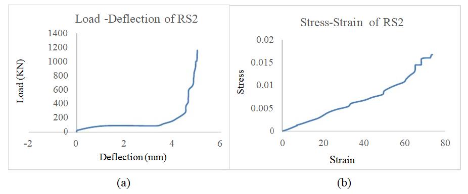
Figure11
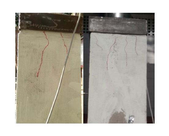
Acolumnwith75%meshconfinementwasplacedunderthe loadingframefortesting.Afterthedurationof495.4sec,the initialcrackstartedattheloadof1056.7KN.Thepatternof crackformationwasthesameasremainingspecimens.The maximum capacity of the specimen to carry the load was 1157.4KN
12
Inthefigure.13(a),theLoad-Deflectiongraphofretrofitted specimen3showsthatthedeflectioninitiallystartedatthe loadof15KNanddeflectionhasincreasedfrom0.18mmto 0.26mmat88.3KN.Thedeflectionisthenlinearlyincreased andreachesalevelof2.71mmataloadof1010KN.Itisthen rapidly increased from 2.8mm to 7.6mm with a constant increaseofloadfrom1009.6KNto1157.4KNrespectively. Themaximumdeflectionofthememberisat7.6mmwitha loadof1157.4KN.
In the figure. 13(b), the graph shows that the curve is linearlyincreasedwithaninitialstrainoccurringatastress
of 0.00021KN/mm2 up to the strain of 29 with the stress 0.00738KN/mm2.Thenthereisagradualincreaseinstrain upto49alongwiththestressof0.0164KN/mm2 .
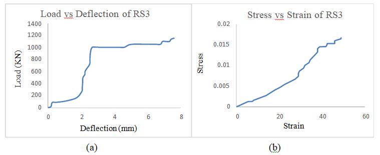
Figure13
Figure14showstheloadcapacitiesofeachspecimen.The control specimen carried the ultimate load of 1008.2KN. Retrofitted specimens were compared with the control specimen. RS1 carried a load of 1096.9KN. RS2 and RS3 reached the ultimate load at 1158.2 and 1157.4 KN. RS2 which was with 50% mesh refinement got high strength concerning RS1 and RS3. As per my consideration, it was recommendedtopreferwrappingwiremeshupto50%was considerable as it gives strength effectively. If more than 50%ofmeshrefinementwasusedthenitgivesalmostsame strengthasit.
Figure15showsthetimeatfailureofspecimens.RS3took 549.8secondstofailitindicatesthatthebrittlenaturehas reduced due to mesh and it increases the ductility of the structureasitwasmoreductilethanCS,RS1,andRS2.
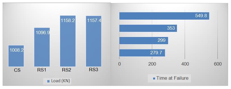
Figure14Loadcarrying capacityofspecimen
Figure15Durationof failureperiodspecimen
Figure16consistsofStress-Straincurves.CSwasstrainedat thelowestvalueof35.5thenRS2wasstrainedatthehighest valueof74.Stress-Strainvariesalongwiththeloadi.e.ifthe loadincreasesalsothereisanincreaseinstrain.
Fromthefigure17,itshowsthevariationsinload-deflection curves of each specimen. The curve of RS1 was linearly increased than that of all specimens. CS was suddenly increasedfromtheloadof149.9KNandRS2alsoincreased fromtheloadof115.9KN.RS3wasmoredeflectedthanthat
International Research Journal of Engineering and Technology (IRJET) e-ISSN: 2395-0056
Volume: 11 Issue: 06 | June 2024 www.irjet.net p-ISSN: 2395-0072
ofallspecimens.Deflectiondependsupontheload-carrying capacity of the member if the load has increased then deflectionmayalsoincrease.
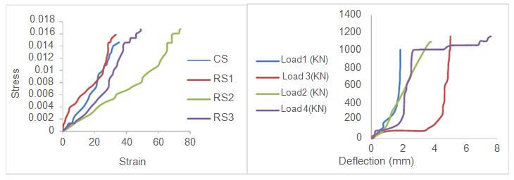
Figure16Stressvs StrainCurvesof Specimens
6.
Figure17Loadvs DeflectionCurvesof Specimens
Observation from all the results of four specimens have concluded that RS2 and RS3 are 1.14 times greaterthanCSandRS1is1.08timesgreaterthanCS.
In comparison between retrofitted specimens, RS2 andRS3are1.05timesgreaterthanthatofRS1
RS2andRS3gotalmostthesamestrengthasRS1and mesh refinement of 50% was suggested for the membersinfuturepurposes.
RS3tookalongtimetofailasitindicatesalessbrittle natureandmoreductilitynatureofthemember.
RS2wasmorestrainedthanotherspecimenslikeCS, RS1, and RS3 as it increased along with the loadcarryingcapacity.
[1]Abd-ELhamed.,Ezz–EldeenM.K.,H.A.,“Retrofitting andStrengtheningofDamagedReinforcedConcrete Columns Using Steel Angles Wrapped with Steel Wire Mesh”, International Journal of Modern EngineeringResearch,2014;4(12),16-24.
[2]Amrul Kaish A.B.M., Alam M.R., Jamil M., Wahed M.A.,“FerrocementJacketingforRestrengtheningof Square Reinforced Concrete Column under Concentric Compressive Load”, ELSEVIER, 2013; 720-728.
[3]Anagha. A.R., Shibi Varghese., “A Study on Strengthening of R.C.C Columns by Ferrocement Jacketing”, International Journal of Science Technology&Engineering,2017;3(11),110-115.
[4]Azam Amir., Amjad Nasser., Orooj Azam., “Strengthening of Existing Building Column Using FRPWrap&GIWireMesh”,InternationalJournalof Scientific&EngineeringResearch,2013;4(5),211216.
[5]Bishnu Gupt Gautam., Lakshmipathy M., Senthil KumaranG.,“ExperimentalStudyonRetrofitting of Square RC Short Column Subjected to Concentric Axial Loading ByJacketing”InternationalJournalof Civil Engineeringand Technology, 2014;5(8),140147.
[6]Manikandeswaran O., Irin Mary Martin., "Comparative Study of Columns Strengthenedby Steel Angles and Ferrocement Jacketing”, International Journal of Research in Advent Technology,2015;10-11.
[7]Muhammad N.S Hadi., Hua Zhao., “Experimental Study of High-Strength Concrete Columns Confined with Different Types of Mesh under Eccentric and Concentric Load”, Journal of MaterialsinCivilEngineering,2011;23(6),1-10.
[8]Muhammed Salih D.S., Arunkumar C., “Strengthening of Reinforced Concrete Column Using Jacketing Technique”, International Conference on Engineering Innovations and Solutions,2016;35-38.
[9] Tore E., Comert M., Demir C., Ilki A., Marasli M., “Seismic Retrofit of Columns Using Basalt Mesh Reinforced Sprayed GRC jacket”, GRC,2015; Dubai,1-7.
[10] Yan Xiao., ASCE M., Hui Wu., “Retrofit of Reinforced Concrete Columns Using Partially Stiffened Steel Jackets”, Journal of Structural Engineering©ASCE,2003;129(6), 725- 732.