International Research Journal of Engineering and Technology (IRJET) e-ISSN: 2395-0056
Volume: 11 Issue: 06 | Jun 2024 www.irjet.net p-ISSN: 2395-0072


International Research Journal of Engineering and Technology (IRJET) e-ISSN: 2395-0056
Volume: 11 Issue: 06 | Jun 2024 www.irjet.net p-ISSN: 2395-0072
Aayush Dhokne1, Manoj Gore1, Mayuresh Desai1, Sudhanshu Gurav1 , Dr. S. V. Chaitanya2
1U.G. Student, Dept. of Mechanical Engineering, AISSMS COE, Pune, India
2Head of Department, Dept. of Mechanical Engineering, AISSMS COE, Pune, India
Abstract - This is a research paper on Design and development of propulsion system using ionic principle. Ion thrusters have emerged as an efficient alternative to conventional propulsion systems due to their high specific impulse, resulting in minimal fuel requirements. While the thrust, they generate is significantly lower compared to chemical propulsion systems, ion thrusters excel in various mission applications, including orbital positioning for geostationary satellites, orbit and attitude control, and versatilemissionprofiles.Unlikechemicalpropulsion,whichis unsuitable for long-duration missions, ion thrusters enable successful long-range missions. Electric propulsion (EP) facilitates numerous strategic missions by NASA and other space agencies, aiding in the exploration of our solar system, the discovery of new planets, stars, galaxies, and potentially habitable Earth-like planets in neighboring systems, and the search for extraterrestrial life. The development of EP technology supports these missions by integrating advanced technologies into ongoing projects. This article provides a conciseoverviewofelectricpropulsionsystems,withaspecific focus on ion thrusters.
Key Words: Ionic Thruster, Corona Discharge, Ions, Propulsion System, Hall Thruster, Spacecraft Travel, Propellent, Final year Project.
An ion thruster is a spacecraft propulsion system that generates thrust by ionizing and accelerating propellant, differing from traditional chemical rockets which rely on combustion. It operates on the principle of electrostatic acceleration of ions, often using gases like xenon [1]. This technology,whichdatestotheearly20thcentury,hasseen significantadvancementsinrecentdecades,particularlyin spaceexploration.Ionthrustersarehighlyefficient,offering much higher specific impulse compared to conventional rocket engines, which is crucial for long-duration space missions due to their fuel economy [2]. The ionization process in these thrusters involves electron guns or RF antennastocreatepositivelychargedions,whicharethen acceleratedbyanelectricfieldtoproducethrust.Although they generate lower thrust than chemical rockets, their abilitytoruncontinuouslyforextendedperiodsmakesthem ideal for position maintenance, orbit control, and interplanetarytravel[3].Thishighefficiencyanddurability make ion thrusters suitable for applications requiring
continuouslow-thrustmaneuvers,suchasstationkeeping, orbitadjustments,andlong-durationmissions[4] Theyare commonly used in geostationary satellites, deep space probes, and scientific missions where efficiency and longevityareprioritizedoverrapidacceleration[5].
Developacomprehensivedesignandmodellingframework for an efficient and reliable ionic thruster, addressing key parameterssuchaspropulsionefficiency,thrust-to-weight ratio, power consumption, and operational stability. This involves optimizing the thruster's geometry, electrode configuration, and power supply to maximize thrust generation while minimizing energy consumption and potentialfailurepoints.Thegoalistoachieveapracticaland scalable propulsion solution suitable for various space missions, from satellite maneuvers to deep space exploration.
Todevelopasmall-scaletechnologydemonstratorthat ispropelledbyionizationofair.
Tounderstandtheworkingofionizationprinciple.
Todevelopathrustwithoutamovingpart.
The ion engine operates on a straightforward principle, using a strong electric field between two grids acting as electrodestoaccelerateheavypositiveions.Theseionsform a high-speed exhaust stream, generating relatively low thrust but achieving high specific impulse (Isp). The propellantmustbeionizedbeforethisprocess. Inanionic thruster,a gaspropellantentersa dischargechamberata controlledrate.Ahot,hollowcathode(negativeelectrode)at the center of the chamber emits electrons, which are attractedtoacylindricalanode(positiveelectrode)around thechamberwalls.Someof the electronscollidewith and ionizeatomsofthepropellant,creatingpositivelycharged ions. These ions are then drawn toward the grids to be accelerated.

International Research Journal of Engineering and Technology (IRJET) e-ISSN: 2395-0056
Volume: 11 Issue: 06 | Jun 2024 www.irjet.net p-ISSN: 2395-0072

Thekeyfunctionalcomponentsofanionthrusterare:
- Ionization Chamber: Controls losses and influences the thruster'sefficiency.
-Grids:Essentialforionextractioncapabilitiesandsubjectto erosionfromionimpacts.
-Neutralizer:Balancesthechargeoftheexhauststream.
-PowerSupplies:Significantlyimpacttheoverallmassand the number of parts, influencing the power system's final weight.
ThehighvoltageDCsupply,whichcanprovideapotential differenceupto150kV(kilovolt),isthebasicrequirementfor theionthruster.Toaccomplishthisrequirementhere,buck regulatorandPhenovoDC3.7to7.4Vto150kVhighvoltage generator Transformer Boost Inverter module through a pushtoonswitch.Althoughthedistributorclaimstogetthe 800kv-1000kvpotentialdifference,theoutputreceivedwas 100kV~150kV at 5V and 0.3A, though this method is not veryefficient,withouttheaccessofhighvoltagemeasuring toolsthisisoneofthereliablemethods.
Coppertubesserveaselectrodesinionicthrustersprimarily due to their superior electrical and thermal conductivity. This allows them to efficiently transmit the electrical currentsrequiredtoionizethepropellant,oftenanoblegas like xenon. These copper electrodes play a vital role in creating the electrostatic field that accelerates the ions, generatingthrust.Furthermore,copper'sexcellentthermal conductivity helps dissipate the heat produced during ionization,preventingoverheatingandensuringthethruster componentsmaintaintheirstructuralintegrity.Themetal's durabilityandresistancetocorrosionmakeitwell-suitedfor the extreme conditions of space, contributing to the longevity and reliability of ionic thrusters on extended missions. The hollow copper of 5mm diameter is used as cathodesharpedgeelectrodes.
The copper wire electrodes are essential in creating the electrostaticfieldthatacceleratestheionstoproducethrust. Additionally, copper's high thermal conductivity helps to dissipatetheheatgeneratedduringtheionizationprocess, which prevents overheating and maintains the thruster's structural integrity. Copper wire of 30 Gauge is used as electrode, sharp edges are created on wire to produce coronadischarge.
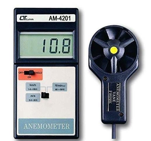
Themostdependabledevicefordetectingwindthrustisthe anemometer.Typically,windvelocityismeasuredusingthis instrument,andthewindthrustcanbeestimatedbasedon thedetector'sarea.Inourstudy,weutilizedtheLutronAM4201portableanemometer,whichfeaturesarangeof0.430m/s,aresolutionof0.1m/s,andanaccuracyof±2%.

3.5 Weighing Scale:
DigitalKitchenWeighingScaleof10kgX1gmisUsed


International Research Journal of Engineering and Technology (IRJET) e-ISSN: 2395-0056
Volume: 11 Issue: 06 | Jun 2024 www.irjet.net p-ISSN: 2395-0072
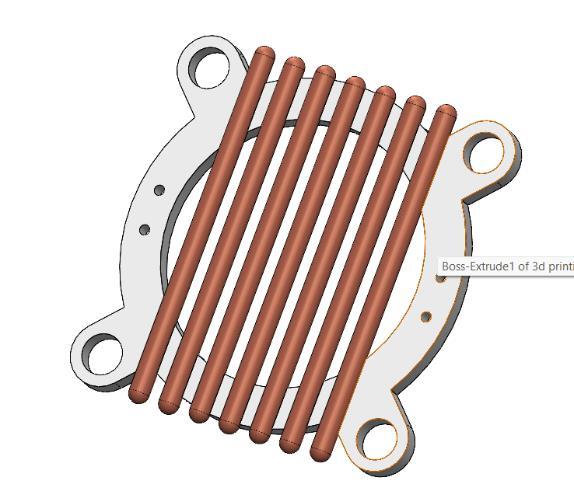
The model for the thrusters has been prepared using SolidWorkssoftware.Itconsistsoftwocircularrings,onefor the anode connection and the other for the cathode connection.Bothringshaveaninnerdiameter(ID)of65mm and an outer diameter (OD) of 85mm. The anode ring featuresagroovetosetawirefilament,whilethecathode ring has a similar design but includes small semi-circular spacesforattachingcopperwires.Themodelisfabricated usingadditivemanufacturing.
Thethrustermodelwasdesignedspecificallyforpropulsion purposesandcreatedusingSolidWorkssoftware.Thedesign includestwocircularrings,eachservingadistinctfunction: onefortheanodeconnectionandtheotherforthecathode connection.
AnodeRing:
Dimensions:Theanoderinghasaninnerdiameter(ID) of 65mmandanouterdiameter(OD)of85mm.Itincludesa groove along its circumference to securely set a wire filament.Thisgrooveensuresthatthefilamentremainsin placeandmaintainsproperalignmentduringthethruster's operation.
CathodeRing:
Dimensions: The cathode ring shares the same inner and outerdiametersastheanodering,withanIDof65mmand anODof85mm.Unliketheanodering,thecathoderingis designedwithsmallsemi-circularspacesalongitsperimeter. Thesespacesarespecificallycreatedtoattachcopperwires, whichareessentialforthethruster'sfunction.
Both rings were meticulously modeled in SolidWorks, leveraging the software's advanced design capabilities to ensureprecisionandfunctionality.Thechoiceofdimensions andfeatures wasdriven by the need to createan efficient andeffectivepropulsionsystem.


The final model was fabricated using additive manufacturing,alsoknownas3Dprinting.Thismethodwas chosen for its ability to produce complex geometries with high precision and minimal material waste. Additive manufacturing allows for the production of the intricate featuresrequiredintheanodeandcathoderings,suchasthe grooveforthewirefilamentandthesemi-circularspacesfor thecopperwires.
Byusingadditivemanufacturing,thedesignensuresthatthe components are lightweight yet robust, capable of withstandingtheoperationalstressesofionthrusters.This approachnotonlyfacilitatestheproductionofcustomparts butalsoallowsforrapidprototypinganditeration,enabling continuousimprovementofthethrusterdesign.
Ionization Chamber: Construct a small-scale ionization chamberusingmaterialsthatcanwithstandhighvoltages andprovidegoodelectricalinsulation.
Electrode Configuration: Design anode and cathode electrodeswithinthechambertocreateanelectricfieldfor ion acceleration, ensuring proper spacing for efficient ionization.
Power Supply: Utilize a high-voltage power supply to generate the necessary electric field for ionizing and acceleratingairions.
Measurement Instruments: Install voltmeters, ammeters, and pressure gauges to monitor voltage, current, and chamberpressureduringtheexperiment.
IonizationProcess:
1.Evacuatetheionizationchambertolowerairpressureand facilitateionization.
2.Introduceairandapplyhighvoltagebetweenelectrodes toionizetheairmolecules.

International Research Journal of Engineering and Technology (IRJET) e-ISSN: 2395-0056
Volume: 11 Issue: 06 | Jun 2024 www.irjet.net p-ISSN: 2395-0072
3. Monitor ionization by measuring current flow and observingpressurechanges.
IonAcceleration:
1.Applyanelectricfieldtoacceleratetheions,ensuringitis strongenoughtoovercomeairdensitydragforces.
2.Measureaccelerationvoltageandcurrenttocalculateion velocity.
ThrustMeasurement:
1.Installathrustmeasurementdevice,suchasabalanceor forcesensor,toquantifythegeneratedthrust.
2. Record thrust readings under varying experimental conditions,suchasdifferentvoltagelevelsorairpressures.
DataAnalysis:
1.Analyzethedatatodeterminetherelationshipbetween appliedvoltage,ioncurrent,andthrust.
2. Calculate the specific impulse and efficiency of the ion thrusterusingthemeasuredthrustandpowerconsumption.

Considerations and Limitations: Air as a propellant has lower ionization efficiency compared to noble gases like xenon, resulting in lower thrust levels. The presence of nitrogen and oxygen in air may lead to the formation of undesirable byproducts,suchasozone,whichcouldaffect experimentalresults.Earth'sgravityandatmosphericdrag impose additional challenges for measuring thrust accurately.

The efficiency of the ion thruster is dependent on thrust created by the ion thruster. Here We will try to make a mathematical model give the thrust created by the ionic wind.Theequationofthrustisgivenasfollows:
F=2��P__ gIsp
Where:
F isthethrustforceinN,
η is theefficiency, Ionic thruster hasapropulsiveefficiencyaround65–80%.
P istheelectricalpowerusedbythethrusterin W,(outputvoltage=150kV,outputcurrent= 0.5Amp)
Isp isthespecificimpulseinseconds,generally ionic thruster has specific impulse around 2000–5000s.
Consideringpropulsiveefficiencyas75%andspecificimpulse as 3000 and substituting values in equation.
F=2x0.75x150x103_x0.5_ 9.81x3000
F=1.7838N
Thethrustcreatedbytheionicwindwillbe1.7838Newtons. Now,wewillcheckwiththeexperimentalvalueoftheforce.

International Research Journal of Engineering and Technology (IRJET) e-ISSN: 2395-0056
Volume: 11 Issue: 06 | Jun 2024 www.irjet.net p-ISSN: 2395-0072
7.1 Experimentation and Validation
EXPERIMENTALPROCEDURE:
Oncedonewiththesetup,movethegridcylinderslider5cm away from the sharp edge electrodes to avoid the direct spark.Startthepowersupplytothecircuit.Wecancontrol the circuit with push to on button. Press the button to initiate the ionization process between the grid cylinders and the sharp edge electrodes. Ensure that the circuit remainsactivefornomorethan10-15secondstoprevent overheatingissues.Positionthefaceoftheanemometer'sfan atananglewhereitregistersthemaximumreadingforthe designated distance between the grid cylinders and sharp edgeelectrodes.Recordthisreading.
OBSERVATIONTABLE:
Table -1: ObservationTable

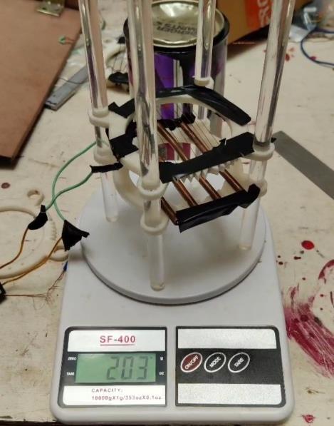
Fig -8: Thrusterplacedonweighingscale
ExperimentalValueofthrustcreatedis0.203kgor1.9914N
As we conclude this experiment, we acknowledge its significanceintheongoingexplorationandadvancementof propulsion technology. The challenges we faced and the insightswegainedserveasinspirationsforfutureresearch and development. Through our investigation of ion propulsion and the use of air as a propellant, we have contributedtoagrowingbodyofknowledgethatwillpropel ustowardnewfrontiers.
3.8
4.0
Next,graduallymovethegridcylindersliderawayfromthe sharpedge electrodesata slowpaceandrecordthewind speed displayed by the anemometer. Repeat this process threetimesforeachpositionandcalculatetheaverageofthe threereadingsforaccuracy.
7.2 Experimentation and Validation Using Weighing Scale
PROCEDURE:
Step1:Puttheionicthrustermodelontheweighingscale.
Step2:Taretheweightofthemodeltozero.
Step3:connectthebatteriesandstartthethruster.
Step4:Notethereadingofweighingscale.
Looking ahead, we envision a future where the principles uncoveredinthisexperimentdrivefurtherinnovationand discovery. By refining ion propulsion techniques and expanding our understanding of its applications, we open doors to numerous possibilities in both terrestrial and extraterrestrial realms. This experiment not only marks a milestone in propulsion technology but also stands as a testament to the relentless pursuit of knowledge and the humanspiritofexploration.
Inconclusion,theexperimentwithanionicthrusterusingair as a propellant underscores the importance of curiosity, innovation, and perseverance in our quest to unlock the universe'smysteries.Aswecontinuetopushtheboundaries of what is possible, we move ever closer to realizing our dreams of exploring the cosmos and deepening our understandingoftheworldaroundus.
1.DeepSpaceExploration:Ionthrustersareutilizedindeep spacemissionsduetotheirhighspecificimpulse,enabling spacecraft to travel greater distances with minimal propellant. This efficiency can benefit future missions to outerplanetsandinterstellartargets.

International Research Journal of Engineering and Technology (IRJET) e-ISSN: 2395-0056
Volume: 11 Issue: 06 | Jun 2024 www.irjet.net p-ISSN: 2395-0072
2.OrbitalStation-KeepingandDebrisRemoval:Ionthrusters aid in satellite station-keeping, allowing satellites to maintain their positions in orbit and prolonging their operationallifetimes.Additionally,ionthrusterscansupport effortstoclearspacedebris.
3.CommercialSpaceApplications:Asthecommercialspace industry expands, ion thrusters can facilitate satellite deployment, constellation maintenance, and in-space transportation.
4.SpaceTourism:Ionthrusterscouldplayasignificantrole in future space tourism missions, providing reliable and efficientpropulsionforlongerjourneysbeyondEarth'sorbit.
5.AdvancedPropulsionResearch:Scientistsaredeveloping moreadvancedionthrustertechnologies,includingmagnetic ionthrustersandotherelectricpropulsionvariants,which couldenhanceperformanceandefficiency.
10. ACKNOWLEDGEMENT
We would like to express our heartfelt gratitude to our project guide, Dr. S. V. Chaitanya, for their invaluable guidance.Wearealsodeeplythankfultoourteammembers, whosecontributionswereessentialtothecompletionofthis project.Additionally,weareindebtedtoourcollegestafffor theirvaluableassistancethroughoutourjourney.Finally,we extendoursincereappreciationtoourfamiliesandfriends fortheirunwaveringsupportandunderstandingduringthe courseofthisproject.
11. REFERENCES
[1] Jet Propulsion Laboratory (NASA), “Power On! Ion Propulsion System.” [Online]. Available: http://dawn.jpl.nasa.gov/technology/ion_prop.asp. [Accessed:09-Jun-2016]
[2] R. G. Jahn and E. Y. Choueiri, “Electric Propulsion. Technology Programmes,” ESA Publications Division, 2002.
[3] E.Y.Choueiri,“ACriticalHistoryofElectricPropulsion: TheFirst50Years(1906-1956),”JournalofPropulsion andPower,vol.20,no.2,pp.193–203,2004.
[4] NASA,“GlennContributionstoDeepSpace1,”14-Apr2015.Available http://www.nasa.gov/centers/glenn/about/history/ds 1.html.[Accessed:23-Mar-2016].
[5] S. Anthony, “NASA’s NEXT ion drive breaks world record,willeventuallypowerinterplanetarymissions.”


AayushDhokne
U.G. Student, Dept. of Mechanical Engineering, AISSMS COE, Pune, India
ManojGore
U.G. Student, Dept. of Mechanical Engineering, AISSMS COE, Pune, India
MayureshDesai
U.G. Student, Dept. of Mechanical Engineering, AISSMS COE, Pune, India
SudhanshuGurav
U.G Student, Dept. of Mechanical Engineering, AISSMS COE, Pune, India
Dr S. V Chaitanya
Head of Department, Dept. of Mechanical Engineering, AISSMS COE,Pune,India