
InternationalResearchJournalofEngineeringandTechnology (IRJET) e-ISSN: 2395-0056
Volume: 11 Issue: 06 | Jun 2024 www.irjet.net p-ISSN: 2395-0072


InternationalResearchJournalofEngineeringandTechnology (IRJET) e-ISSN: 2395-0056
Volume: 11 Issue: 06 | Jun 2024 www.irjet.net p-ISSN: 2395-0072
AshinaT.R1,FathimaSThaikudiyil2,Dr.GeorgeKGeorge3
1Post Graduate student, Department of Civil Engineering, KMEA Engineering College, Edathala Ernakulam. Kerala
2Assistant Professor, Department of Civil Engineering, KMEA Engineering College, Edathala Ernakulam, Kerala
3 Assistant Professor, Department of Civil Engineering, KMEA Engineering College, Edathala Ernakulum, Kerala
Abstract - Reduced beam section design provides a more predictable and reliable behavior at the beam column connection during seismic event. RBS enhances the ductility of the beam and it made the column safe from overall collapse of a structure but it reduced the load bearing capacity of beam considerably.to overcome the lack of moment capability of beam this study aims to implement a pretensioning bolt with plate welded across the RBS. The main objective of this paper is to evaluate the performance of reduced beam section(RBS) with various design modification,specificallyfocusingonstrengtheningmethods involving bolts and plates. The study aims to determine whether the diameter of bolts used in these strengthened RBS designs influences the load bearing capacity of the beam.
Key Words: Reduced beam section, loadbearingcapacity, collapse,beam,column,bolts.
A moment resisting frame (MRF) is a structural system commonlyusedinbuildingstoresistlateralloads,suchas those generated by wind or earthquakes. It consists of beams and columns connected together to form a rigid frame that can transfer and distribute these loads throughout the structure. MRFs are highly efficient in terms of material usage and construction costs. They can provide a high strength-to-weight ratio, allowing for lighter and more economical designs compared to other structural systems they offer flexibility in architectural design by providing open floor plans with minimal obstructions. The absence of diagonal bracing allows for more usable space and better utilization of the building. MRFs can provide an aesthetically pleasing appearance due to their clean and unobstructed structural lines. This makes them suitable for modern architectural designs. MRFstypicallyhaveredundantloadpaths,meaningthatif one member fails, the load can be redistributed to other members. This enhances the overall robustness and resilienceofthestructure.robustnessandresilienceofthe structure.
Lateral stability is a crucial aspect in the design and performance of moment resisting frames (MRFs) during seismicevents.Seismicstabilityjointsarecommonlyused inMRFstoenhancetheirlateralstabilityandensuretheir
ability to withstand strong earthquake forces. Seismic stabilityjointsaredesignedtoprovidecontrolledyielding andenergydissipationduringseismicevents.Thesejoints are typically located at specific levels along the height of the MRF, such as at beam-column connections or at the baseofthestructure.Theperformanceofseismicstability jointsiscriticalinensuringtheoverallstabilityandsafety of MRFs during earthquakes. These joints must be designed to have sufficient strength and ductility to withstand the anticipated seismic forces without failure. Additionally, their behaviour under cyclic loading conditions should be carefully considered to ensure that they can sustain multiple seismic events without significant degradation in performance. Several factors need to be considered in the design and evaluation of seismic stability joints. These include the selection of appropriate joint types, such as fuse elements or energy dissipating devices, as well as the determination of their capacityandbehaviourunderdifferentloadingconditions. The detailing of these joints is also crucial to ensure proper load transfer and avoid potential weak points or failuremodes
During 1994Northridge,CA earthquake,the beam flangecolumn flange weldments in steel MRF failed at much lower than anticipated load and drift levels. Thus structuralengineersintroducedRBS,whichappearstothe most economical new design method. The RBS protects the welded connection by forcing the plastic hinge in a beamtoformawayfromthecolumnface.Traditionallyit’s a strong column weak beam combination Reduced Beam Sections (RBS) design provides a more predictable and reliable behaviour at the beam-column connection during seismic events. The purpose of an RBS is to enhance the ductility of the beam. By reducing the beam section's width and depth at the ends, the plastic hinge formation canbecontrolledandconfinedwithinthereducedsection. This allows for controlled yielding and energy dissipation during seismic events or other loading conditions, improving the overall ductility of the beam. Providing reduced beam sections on beams instead of the beamcolumn interface allows for improved ductility, maintains the flexural capacity of the beam, preserves the column's design integrity, and facilitates construction processes. The disadvantage faced in RBS is that it reduced the momentcapacity.

Volume: 11 Issue: 06 | Jun 2024 www.irjet.net p-ISSN: 2395-0072
A pretension bolt often referred to as preloaded bolt. It’s a type of fastener which is tightened to a particular tension before it is subjected to an external load. This tensioning ensures the bolt can effectively handle applied loads during service, which improves performances and reliability. Pretension bolts are commonly used in structural applications such as in the construction of building,bridgesandotherinfrastructures.
Theanalyticalstudyconsistsof5modelswithandwithout
Strengthening of RBS and the values of each models are compared. Additionally, critical aspect of this study is ensuring that the plastic hinge formation remains within the RBS region of the beam and doesnot relocate due to modification The cut value of RBS are calculated as per AISC-358specification
R=radiusofcut=(4��2+b2
Wherebf=flangebreadthofbeam,d=depthofbeam
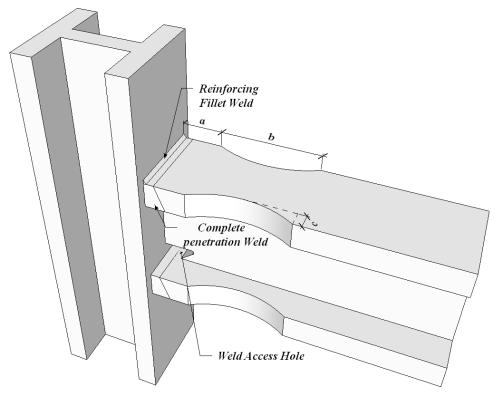
Table -1: Differentmodelswithdesignparameters.
Model1 a=50 b=130c=10
Model2 a=75b=175c=25
Model3 a=62.5b=150c=17.5
Model4 a=75b=130c=10
Model5 a=50b=175c=25
Here the both ends of columns are fixed and the end of beam is free so that the cyclic load is given at the tip of beam in downwards direction. The height of column and thelengthofbeamis975mmand1000mm
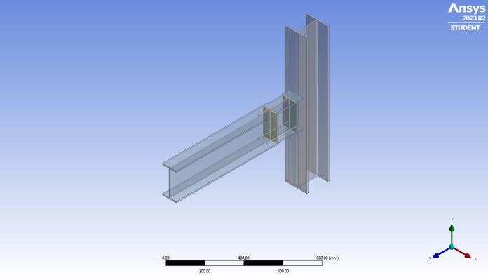
TheRBSregionisstrengthenedwiththehelpof4boltsand a plate across the plastic hinge region. Bolts provide additional shear and tensileresistance, helping to transfer load and improve the overall rigidity of the connection. Platesareaddedtoreinforcethereducedsectionproviding additionalcross–sectionalareaandstiffness
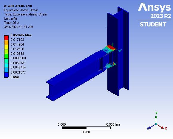
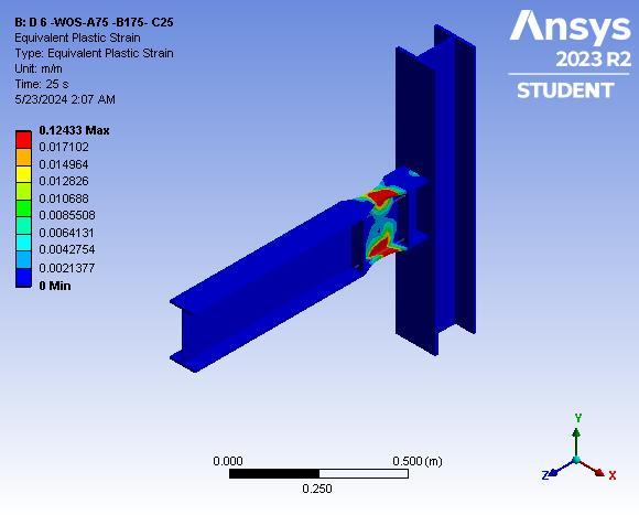
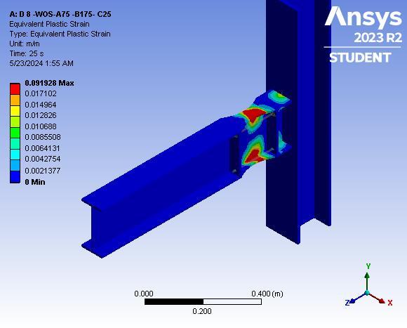
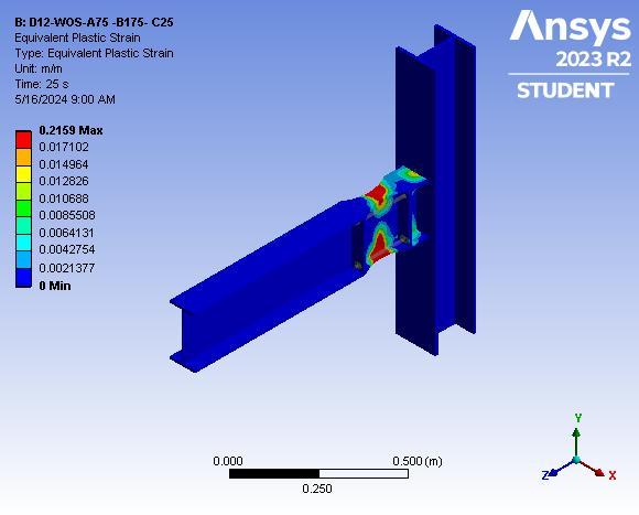
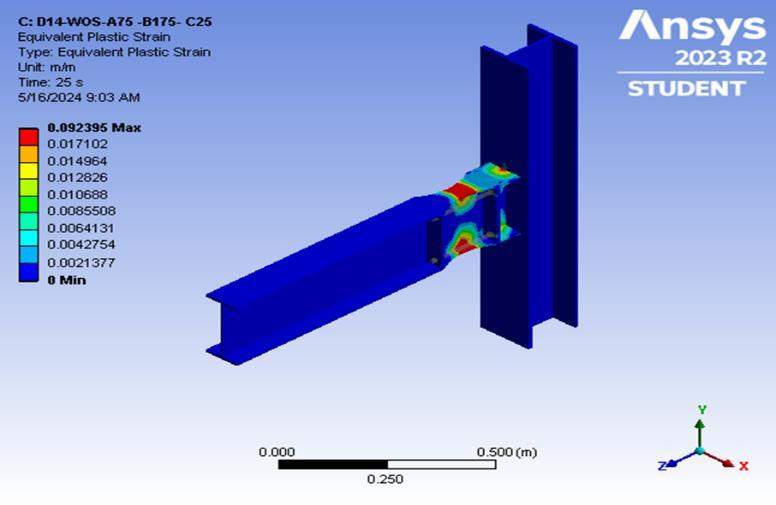
Theequivalentplasticstrainofallmodelsarelistedbelow

Volume: 11 Issue: 06 | Jun 2024 www.irjet.net
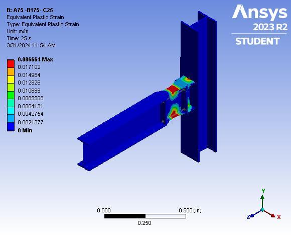
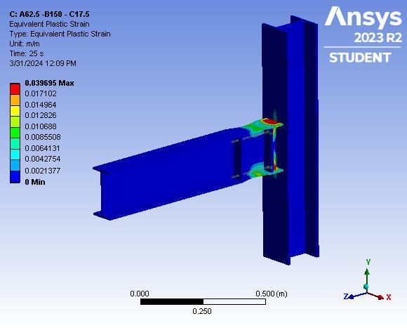
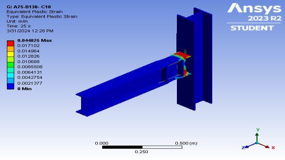
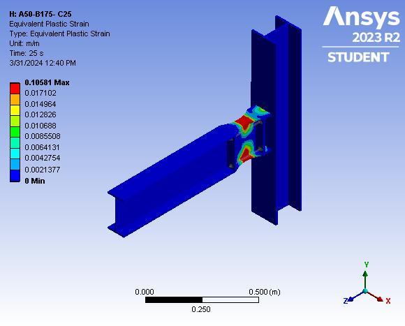
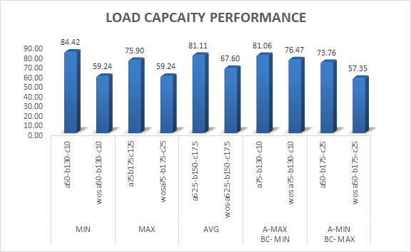
Fig -8: Loadcapacityperformanceofmodelwithand withoutstrengtheningofRBS
Theloadbearingcapacityvariesfromoneanother.Butitis observed that the plastic hinge is relocating from the RBS portion which is not acceptable. The model a50-b175-c25 is the best option as there is no plastic hinge relocation from the RBS portion. The load bearing capacity of a50b175-c25 is 73.76 KN with 26.62 percentage increase in strength than the model a50-b175-c25 without strengtheningwithadriftvalueof3%.
So for further analysis we can take the model a50-b175c25.
The behavior of model 5 under different diameters of bolt 6mm,8mm,10mm,12mm,14mm,16mm,18mm,20mm.isconsideredforthestudy.

InternationalResearchJournalofEngineeringandTechnology (IRJET) e-ISSN: 2395-0056
Volume: 11 Issue: 06 | Jun 2024 www.irjet.net p-ISSN: 2395-0072
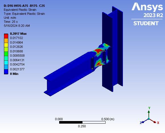
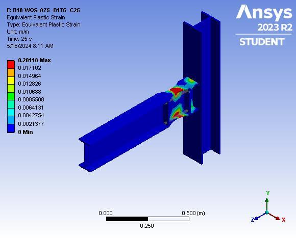
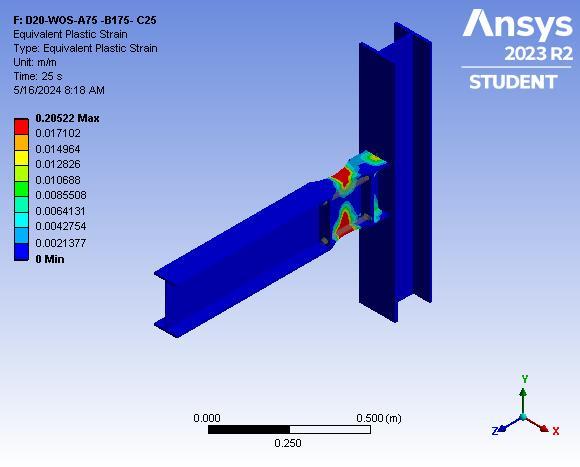
3.1 Equivalent plastic strain of strengthened RBS models


Volume: 11 Issue: 06 | Jun 2024 www.irjet.net
Table: Resultsofmodel5withvariousdiameters
The analysis of model with various diameter started with 6mm, the deformation of beam was 18.7 mm with a load carrying capacity of 64.3kn and drift percentage of 1.at 8mm the deformation of beam was 23mm with load carrying capacity of 73.47 kN and drift percentage of 2.at 10 mm the deformation of beam was 27mm with load bearing capacity of 73.62 kN and drift percentage of 3. at 12mm the deformation of beam was 23mm with load carryingcapacityof74.28kN anddriftpercentageof2.at 14 mm the deformation of beam was 23mm with a load carryingcapacityof74.44kNanddrift percentageof 2.at 16 mm the deformation of beam was 23mm with a load carryingcapacityof74.43kN anddriftpercentageof2.at 16mm the deformation of beam was 23mm with a load carryingcapacityof74.43kN anddriftpercentageof2.at 18mm the deformation of beam was 23mm with a load carryingcapacityof74.44kN anddriftpercentageof2.at 20mm the deformation of beam was 23mm with a load carryingcapacityof74.44kNanddriftpercentageof2.

Fromthe abovegraphitis observedthat diameter of bolt dosent have a crucial role in increasing the moment capability. Diameter 8mm,10mm,12mm, is much more capable in bearing the load, but from 14mm onwards the moment capability remains almost same.as we increase thedia itis foundthat the plastichingeis relocating from
the RBS region to column face and the beam is getting distorted.Theloadbearingcapacityis74.4kNthroughout after 12mm of bolt diameter.it is because of the beam distortion as the bolt gets restrained. From 12 mm the plastic hinge is relocating from the beam to column and thebeamisgettingdistortedhenceitisadvisabletouse8 mm to 10 mm dia of bolt to attain maximum moment capacityofbeamwithstrengthenedRBS.
Reducing the beam section, known as a Reduced Beam Section (RBS), is a common technique to enhancethesafetyofcolumnsfromcollapsebypromoting ductile behavior and controlling the formation of plastic hinges. However, this reduction typically results in a decreased load-bearing capacity. To address this limitation, strengthening the RBS can be implemented to increase its load-bearing capacity while still maintaining the formation of plastic hinges within the RBS portion. One methodofstrengtheningisbyusingboltswithplates. When bolts with plates are employed, they effectively redistribute the applied loads, providing additional supporttotheRBS.Thisredistributionofforcesallowsthe RBS to carry higher loads without compromising its structural integrity. The diameter of the bolts, along with thesizeand thicknessoftheplates, plays a critical role in determining the extent of load capacity enhancement. However, it's important to note that increasing the diameter of bolts with plates can only enhance load capacity up to a certain point. Beyond this threshold, the excessive pressure exerted by the bolts and plates may lead to structural failure due to bolt restraint or other failure modes. Therefore, careful analysis and consideration are necessary to optimize the size and placement of bolts with plates to ensure both increased loadcapacityandstructuralsafety
Theconclusionsobtainedare,
•Indeed,implementingaReducedBeamSection(RBS)can significantly enhance the safety of a column by improving its ability to withstand seismic or other types of loading. By strategically weakening the beam section near the column, the RBS encourages controlled plastic hinge formation, which helps dissipate energy and prevents sudden,catastrophiccollapseduring extreme events. This design approach is a fundamental aspect of ensuring structural resilience and safety in buildings and other engineeredstructures
•ReinforcingtheReducedBeamSection(RBS)withplates andboltscanindeedincreasetheload-bearingcapacityof the structure. By adding plates and bolts, the connection between the beam and the column becomes stronger and more resistant to applied loads. This reinforcement redistributes forces more effectively, allowing the RBS to carry higher loads without compromising its structural

InternationalResearchJournalofEngineeringandTechnology (IRJET) e-ISSN: 2395-0056
Volume: 11 Issue: 06 | Jun 2024 www.irjet.net p-ISSN: 2395-0072
integrity. This method helps optimize the performance of the structure, enhancing its ability to withstand various loading conditions while maintaining the benefits of the RBSdesignintermsofsafetyandresilience.
• Increasing the diameter of bolts in a Reduced Beam Section (RBS) can indeed enhance the load-bearing capacity of the structure up to a certain point. Larger diameterboltsprovidegreaterresistancetoappliedloads and can effectively transfer forces between the beam and the column. This increased capacity allows the RBS to carry heavier loads without compromising its structural integrity. However, it's essential to consider the limits of bolt diameter increases, as excessively large bolts may leadtostructuralissuessuchasexcessivepressureonthe surrounding material or bolt restraint failure. Therefore, carefulanalysisandengineeringjudgmentarerequiredto determine the optimal bolt size to maximize load-bearing capacitywhileensuringstructuralsafety.
1. Anastasiadis, Anthimos S., Marius Mosoarca, and Victor Gioncu. "Design aspects of reduced beam sections for IPE and HEA European profiles." 8th National Conference on MetalStructures,Xanthi.Vol.29.2005.
2. Chen, L., and Y. C. Wang. "Methods of improving survivability of steel beam/column connections in fire." Journal of Constructional Steel Research 79 (2012): 127139.
3. Di Benedetto, Sabatino, et al."Seismic behaviour of steel Moment Resisting Frames with traditional and innovative connections." Procedia Structural Integrity 44 (2023): 1901-1908.
4. Indupriya,G.,andB.Anupriya."Analytical Evaluation of RBS Moment Connection for Indian Profiles Under Seismic Behavior." International Journal of Sustainable Construction Engineering and Technology 13.3 (2022): 90-106.
5. Loulelis, D., G. D. Hatzigeorgiou, and D. E. Beskos. "Moment resisting steel frames under repeated earthquakes." Earthquake and Structures 3.3-4 (2012): 231-248.
6. Moore, Kevin S., James O. Malley, and Michael D. Engelhardt. Design of reduced beam section (RBS) moment frame connections. Los Angeles: Steel Committee of California,1999.
7. Nia, Z. Saneei, M. Ghassemieh, and A. Mazroi. "WUF-W connectionperformancetoboxcolumnsubjectedtouniaxial and biaxial loading." Journal of Constructional Steel Research88(2013):90-108.
8. Quayyum, Shahriar, and Tasnim Hassan. "Seismic performance of a fire-exposed moment-resisting frame." Journal of Structural Engineering 144.11 (2018): 04018206.
9. Rackauskaite, Egle, et al. "Computational analysis of thermal and structural failure criteria of a multi-storey steel frame exposed to fire." Engineering Structures 180 (2019):524-543.
10. Radzi, Noor Azim Mohd, et al. "A Review of the Structural Fire Performance Testing Methods for Beam-toColumn Connections." Advances in Civil Engineering 2021 (2021):1-18.
11.Saleh, Aboozar, Seyed M. Zahrai, and Seyed R. Mirghaderi."Experimental study on innovative tubular web RBS connections in steel MRFs with typical shallow beams." Structural Engineering and Mechanics, An Int'l Journal 57.5(2016):785-808.
12. Swati, Ajay Kulkarni, and Vesmawala Gaurang. "Study of steel moment connection with and without reduced beam section." Case Studies in Structural Engineering 1 (2014): 26-31.
13. Taiyari, Farshad, Antonio Formisano, and Federico M. Mazzolani. "Seismic behaviour assessment of steel moment resisting frames under near-field earthquakes." International Journal ofSteel Structures19(2019):14211430.
14. Wilkinson, Sean, Gordon Hurdman, and Adrian Crowther. "A moment resisting connection for earthquake resistant structures." Journal of Constructional Steel Research62.3(2006):295-302.
15. Eslami, Mohammadreza, Abbas Rezaeian, and Venkatesh Kodur. "Behavior of steel column-trees under fire conditions." Journal of Structural Engineering 144.9 (2018):04018135.