

Design and Performance Analysis of Several Antennas Using CST
Md. Mayn Uddin#1, Md. Uzzal Mia#2, Md. Kamruzzaman Sumon#3
1,2,3Department of Electrical and Electronic Engineering, Jatiya Kabi Kazi Nazrul Islam University, Trishal, Mymensingh-2224, Bangladesh
Abstract: The demand for smaller, lighter, and higherperformance antennas in communication systems has increased. Microstrip antennas are one of the most common antenna types that can suit these requirements. Theyhavenumerousadvantages,includingsmallsize,ease of fabrication, and low cost. In addition to these benefits, they have drawbacks, such as limited bandwidth. The performance parameters of antennas, such as directivity, voltage standing wave ratio, S-parameter, gain, and directivity, have been calculated and compared. The copper-coated substrate material is FR-4 lossy with a dielectric constant of 4.4 and a thickness of 1.5 mm, and the design frequency is 2.4 and 8-12GHz. The feeding mechanism utilized is a 50-ohm microstrip feed line. This paper compares five types of antennas: rectangular microstrip patch antenna, circular patch antenna, dipole antenna, array antenna, and double T shape microstrip patch antenna. We aim to achieve higher gain and efficiency while minimizing the size and cost. Therefore, we are carefully choosing to construct an antenna with a specific frequency and wavelength to meet the required gainandefficiency.Theantennahasthreeslots,oneonthe groundplaneandtwoonthepatch.CSTMicrowavestudio tools replicate the desired patch antenna design. We have used CST microwave tools software to implement this proposed model and achieve good results. Our utmost efforthasbeenmadetoachieveoptimumaccuracy.
Keywords - Antennas, Gain, Directivity, S-parameter, PolarPlot,VSWR
1. INTRODUCTION
Today's digital communication systems require compare, compatible, and affordable antennas. An antenna is an electrical inducer, that converts electromagnetic waves into electrical signals. An antenna produces radiation. When the current inside the conductor is altered, radiations occur by directly increasing or reducing the current wire. This results in a discontinuity within the conductor causing the antenna emitting [1]. Microstrip patch antennas have several advantages over traditional antennas, including reduced weight, volume, and cost, a lower profile, smaller dimensions, easy manufacture, and
conformance [2]. Microstrips are used in a variety of applicationssuchasradars,telemetry,aircraft,navigation, radiofrequency identification (RFID), biomedical systems, themedicalindustry,mobileandsatellitecommunications, missile systems, a global positioning system (GPS) for remote sensing, and so on, due to their compact size and planar structure [3]. The patch, substrate, and ground plane are the three essential components of the MPA design. The copper-based component known as the radiating patch is connected to the top layer of the substrate, while the ground plane is connected to the bottom layer, as depicted in Figure 1 [4]. Due to its characteristicsandability toadopt anygeometricalshape, MPAs have been one of the best candidates for wireless applications. MPAs are divided into four categories [5]. These antennas can be designed and shaped based on the parameters. Patch antennas are available in several shapes,includingrectangles,squares,triangles,andcircles. Acomparisonofvariouspatchantenna shapesisincluded [6].CircularandrectangularMPAsarepopularduetotheir construction and wide range of applications, providing feedline flexibility, a wide frequency range, and increased bandwidth.Eachchangeinthepatch'sdesigncanresultin a new application. This study introduces a new circular antenna approach that uses aperture-coupled line feeding asdescribedinthereference[7].
Basedonperformance, a circular andrectangularantenna operatingintheXbandataresonantfrequencyof10GHz are compared [8], with the rectangular patch antenna outperforming the circular. For a variety of uses, microstrip antennas can also be constructed in the forms of E, Z, T, S, H, and F [9], which describes four different shaped antennas and their outcomes The examination of changes in antenna properties due to form change is presented. A T-shaped device that can switch its polarization in both directions i.e. left and right circular polarization [10]. For wireless communication systems, thedesignedantennaprimarilytargetstheIEEE802.11b/g frequency spectrum (2.4-2.5GHz). With symmetry on two polarization modes, 8.7 dB maximum gain and 7.1% bandwidth effectiveness are achieved. It behaves as an internal antenna. Its principal application is with microwave frequencies. A patch antenna is similar to a
International Research Journal of Engineering and Technology (IRJET) e-ISSN:2395-0056
Volume: 11 Issue: 06 | Jun 2024 www.irjet.net p-ISSN:2395-0072
patch of different-shaped metal foil on a printed circuit board (PCB), with a metal foil ground plane on the other side.
It is created of two metallic plates layered on ascend of one another and mounted on a small, rectangular, flat surface. Compared to conventional antennas, microstrip patchantennasprovideadditionalbenefitsandprospects.
•Lessexpensive
•Lighterinweight
•Lowervolume
•Lowerprofile
•Smallerinsize
•Easiertofabricateandconform
A Microstrip Antenna's most basic configuration consists of a ground plane and a radiating patch on opposite sides of a dielectric substrate. When current from a feed line touches the strip of a microstrip or patch antenna, electromagnetic waves are formed The patch's waves begintospreadoutfromthewidth side. Wedesigned and built a microstrip patch antenna. The patch antenna efficiency at 2.4 GHz is roughly 80%, according to the measurements. There are several techniques to increase antenna bandwidth, such as utilizing different antenna shapes, cutting slots, probe feeding, and thickening a substratewithalowdielectricconstant.
Microstripantennashavethefollowingadvantages:
•Conformal structuresare conceivable(curvesaresimple tobuildaslongastheyarejustinonedirection).
•Lowfabricationcosts
•Formingabigarraywithhalf-wavelengthorlessspacing issimple.
•Compactsize Disadvantagesinclude:
•Limitedbandwidth
•Increasedcomplexity
•Lowpowerhandling.
2. OBJECTIVES
We want to compare the gain efficiency, directivity, Sparameter, and polar plot for rectangular, circular, dipole, arraymicrostrippatchantenna,anddoubleT-shapepatch antennasinthe8-12GHzfrequencyrangeandidentifythe ideal operating frequency for these antennas. We aim to achieve increased gain and efficiency while minimizing size and reducing cost. As a result, we must construct an antenna with a specified frequency and wavelength to achieve the needed gain and efficiency while also meeting therequirementsofminimal sizeandlowcost.Evaluating
andcomparingtheperformanceofdifferentfrequenciesis critical. The antenna is being developed with the CST microwavestudiotool.
3. METHODOLOGY
In our methodology, we explain our process for collecting data. For example, we detail how we run experimental tests on samples, and use current data to develop new studies. Our methodology section includes a full description of our activities and procedures. Initially, we learnedabouttheantennathatweaimtocreate.Welearn howtouseCSTMicrowaveStudiotoolsforantennadesign. Following that, we will design and simulate the antennas, and then present the antenna output for all of them. Finally,wecomparedifferentantennas.
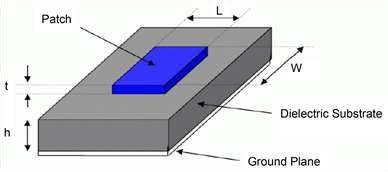
1: Structure of a Microstrip Patch Antenna
Figure 1 shows the layout of a simple Microstrip Patch Antenna (MPA), The MPA is built using microstrip line feeding technology, which results in a smooth antenna surface design Different designs are created for the different frequencies like the 2.4 GHz frequency, which is widely used in Applications in science, industry, and medicine becauseitisanunlicensedfrequency [11] All of these proposed antenna design is simulated using CST microwavestudiotools.Below,youcanfindourworkplan andasuitableflowchart.
Figure
International Research Journal of Engineering and Technology (IRJET) e-ISSN:2395-0056
Volume: 11 Issue: 06 | Jun 2024 www.irjet.net p-ISSN:2395-0072
4.
PROPOSED MODEL

Start
Study about antenna


Parameter calculation

Antenna design

Simulation of antenna
Output of simulation


Figure 2: Flowchart


International Research Journal of Engineering and Technology (IRJET) e-ISSN:2395-0056
Volume: 11 Issue: 06 | Jun 2024 www.irjet.net p-ISSN:2395-0072
5. Literature Review and Theoretical Framework:
Rectangular Microstrip Patch Antenna
Antennas are important components in signal transmissionandreception.Microstrippatchantennasare widely used in wireless communication systems because of their advantageous characteristics, which include compatibility, low cost, small weight, and ease of fabrication.[12].
Industrial, Scientific, and Medical band with 2400-2490 MHz is the most popular band type utilized for microstrip patch antennas in residential, office, and industrial applications. WLAN is an IEEE (Institute of Electrical and Electronics Engineers) wireless network (Wireless Local Area Network) IEEE 802.11 is the overall name for the standard,andIEEE802.11bandIEEE802.11garetheISM wireless LAN standards that operateinthe2.4GHz range. Many studies have been carried out to increase the bandwidthandgainofantennas[13][14][15].Owingtoits low cost and ease of production, the Microstrip Patch Antennafinds extensive application in wireless communication. Its direct printing on PCB makes it very convenient. In this research, the substrate used is a lossy FR-4 material. Mounting a metal patch over a wider ground plane is necessary for the microstrip antenna element. A microwave substrate having a relative permittivityoftwototenisusuallyusedtoprintthepatch. Depending on the application, however, A variety of materials may be used. The lowest loss and highest radiation productivity are typically seen in air or lowthickness froths. [16][17]. A crucial part of the microstrip antennaisthefollowingpatch,whichhasanimpactonthe radiationpattern,impedancematching,bandwidth,return loss, interface current dispersion, and harmonic suppression. [18][19]. A metallic radiating surface on top ofaconnecteddielectricfoundationwithapredetermined thickness forms the basis of an MSA's usual construction. [20].
Nowadays,thesurfacepatchantennaiswidelyutilizeddue to its multiple benefits. However, it has some disadvantages, but they are very little to its numerous advantages.MSAoffersthefollowingadvantages:-
a)Lightweight;
b)Low-profile;
c)Dualandtriplefrequencycapability
Thedisadvantagesofantennasare:
•Lowgain
•Lowbandwidth.
To address this issue, the designer designed a variety of microstrip antennas for their test. They first created an MSA with a single substrate layer and then calculated factors such as gain, visibility, return loss, plus voltage standing waves ratio. After that, they produced a second MSAwithtwounderlyinglayers,stackingthesecondlayer ontopofthefirstusingthesamematerial.Finally,theycut diagonal slots into the MSA, and in the final effort, slots were cut in all four corners of the MSA, For a comparison of the antennas' performance metrics. This initiative intends to fulfill the expanding need for wireless connectivity in a range of contexts. The primary focus of thisresearchisto:-
A. Boost the bandwidth of an antenna.
The antenna's range can be enhanced by increasing the antenna'sheightandloweringthedielectricconstant.
B. Boost an antenna's gain.
A patch's form can be changed to increase a gain; in this paper, a rectangular patch is employed since it reduces patch area by 65-70 percent while simultaneously improvinggain.
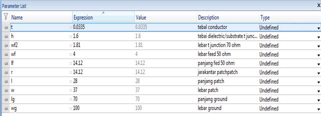
Antenna Design and its Dimensions: Fig. 3 shows the suggestedantennamathematicalterms,whichconsistsofa stripesinputline,patch,andinsulatingsubstrate.WithFR4 lossy, the rectangular patch is segregated from the underlying plane. A dielectric substrate that has the followingmeasurements[21].
Table 1. ProposedAntennaDimensions[20]
The table above displays all of the MSA's planned parameter dimensions. The construction of a rectangular microstrip patch antenna is seen in the image. It is composed of a base plane, a patch, and a substrate of dielectric(FR-4).[14].The antenna'sresonance frequency ("fo"), substrate thickness ("h"), and substrate material's dielectricconstant("εr")areimportantfactorstoconsider. In this investigation, appropriate substrate materials
include FR-4 with relative dielectric constant εr=4.4, height h=1.6 mm, and ground thickness of t=35 μm. This studyseekstoreducereturnlossbymaintainingh,εr,and fo constant while optimizing other parameters. Using the supplied values, the patch width (Wp) is computed using equation(1)asfollows:Wp
Where:
c=free-spacelightvelocity
fo=resonancefrequency.
εr=dielectricconstant.
Since microstrip antennas do not have a homogeneous structure,itcausesachangeintheelectricaltransmittance value.
��reffiscalculatedbyequations2and3.
………………3

Leff is the effective length of the patch and ΔL represents thelengthaugmentationcalculatedbyequations4and5.
As a result, Wp=36 mm, Lp=28.68 mm are found. The width of the ground plane is determined as Wg=65 mm and the length as Lg=65 mm. The Microstrip feeding methodisusedasthefeedingmethodandthelengthofthe transmission line is optimized as 14.75 mm and the thickness as 1.6mm.The width ofthetransmissionlineis determined by changing it according to the impedance match. Two symmetrical slots are made on the patch surface of the antenna. Another slot was opened on the groundplane.Thesimulationsofthedesignedantennaare carriedoutontheCSTStudioSuite.
Design: How to design the rectangular patch antenna is givenbelow
Step1:OpenCSTmicrowavestudio.
Step2:Selecta new project then mw/RF and Optical then select antennas then select planar (patch, slot) then select timedomain.
Step 3: Select minimum and maximum frequency range and give a working frequency list then select all monitors likeE-field,H-field,far-field,etc.
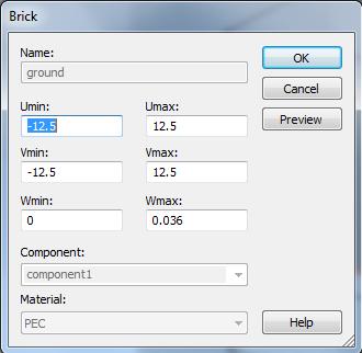
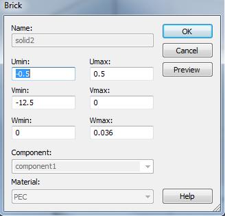
Step 4: Select modeling then select brick then press ESC andgivethevalueasgivenbelow.
Ground:Xaxis–w/2tow/2,Yaxis–l/2tol/2,Zaxis0to–g.
Substrate:Xaxis–w/2tow/2,Yaxis–l/2tol/2,Zaxis0to–g
feedline:Xaxis–wf/2towf/2,Yaxis0to18.16,Zaxis0tog patch:Xaxis–wp/2towp/2,Yaxis–lp/2tolp/2,Zaxishto h+g.

Simulation Output:
Antennasimulationstepsaregivenbelow.
Step1:Calculatewaveguideportsbymacrosfunction.
Figure 3: Microstrip Patch Antenna.
Figure 4: Rectangular Patch Antenna.
International Research Journal of Engineering and Technology (IRJET) e-ISSN:2395-0056
Volume: 11 Issue: 06 | Jun 2024 www.irjet.net p-ISSN:2395-0072
Step 2: Select simulation then select pick face of feed line thenselectwaveguideportoptionandgivethevaluefrom thecalculation.
Step 3: Select simulation then select setup solver and set accuracy -40db, normalized to fixed Impedance 50ohm thenpressstart.
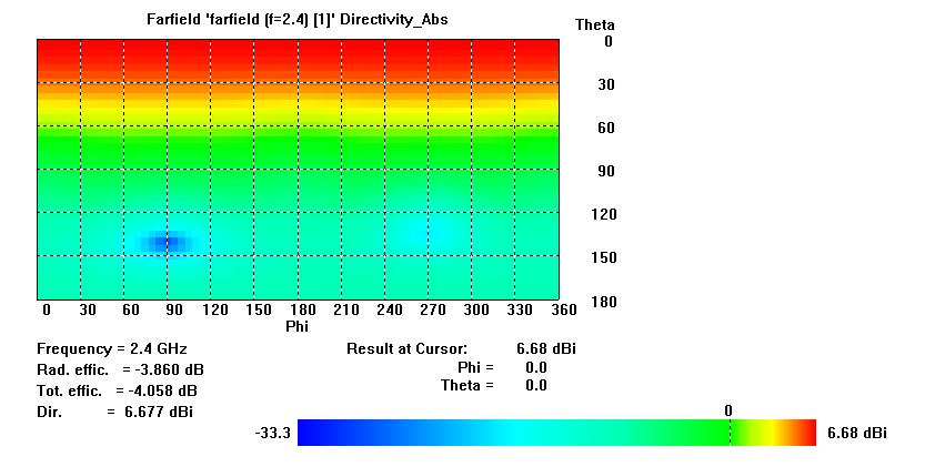
Step 4: After completing the simulation double-click farfieldsandselectthefrequencywhichthefar-fieldwantsto show.
Step 5: Make a performance table at different frequencies which includes operating frequency, total efficiency, radiationefficiency,gain,anddirectivity.
Step6:ToshowS-parameterdoubleclick1-Dresultsthen select S-parameter and to show bandwidth add curve markerat-10dbpoints.
Step7: ToshowVSWR double-click 1-Dresults and Select theVSWRoption.
Step 8: To show the polar plot double click far-fields and selectpolarform.
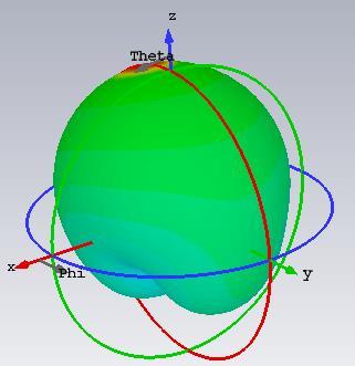
Step 9: To show a 2-D plot double click Far-fields and select2D.


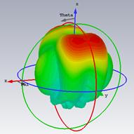

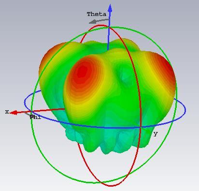

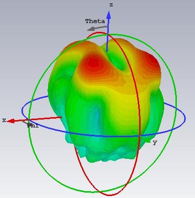

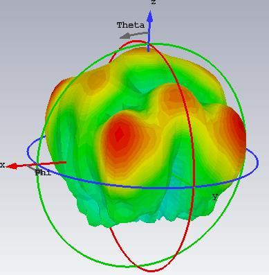
Figure 5: Rectangular Patch Antenna Far-fields at Different Frequencies.
Table 2: Performance Analysis of Rectangular Patch Antenna at Different Frequencies
International Research Journal of Engineering and Technology (IRJET) e-ISSN:2395-0056
Volume: 11 Issue: 06 | Jun 2024 www.irjet.net
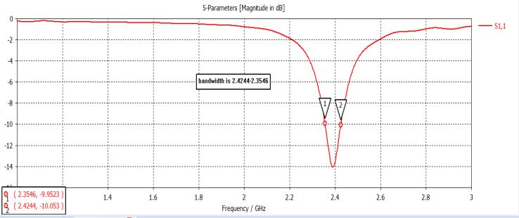
6: S-parameter of Rectangular Patch Antenna.
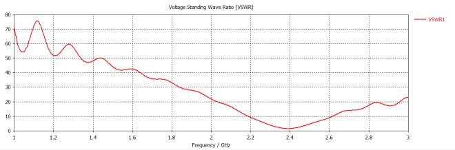
7: VSWR of Rectangular Patch Antenna.
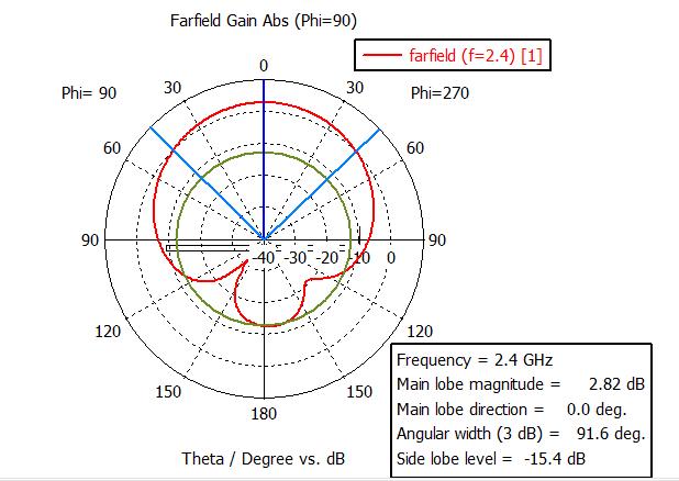

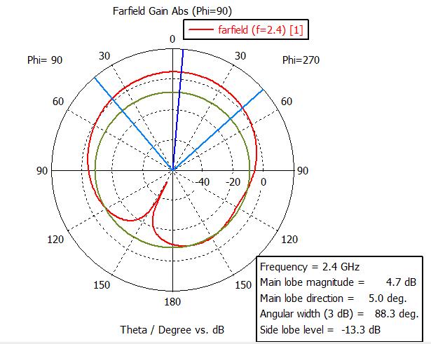
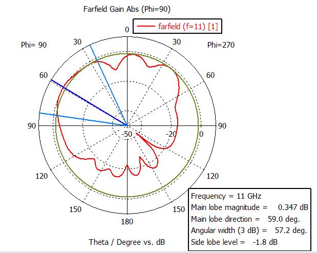
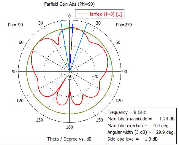
8: Polar Plot at Different frequencies of Rectangular Patch Antenna.
Figure
Figure
Figure
Circular Patch Antenna
ThecircularpatchantennaismadeofFR4-lossy,whichhas a gain of 3 dB and is 4.4 KE, 1.6 mm high. It measures return loss, bandwidth, directivity, antenna gain, and productivity, among other antenna characteristics. Microstrip antenna with a circular patch can be used for WLAN (wireless local area network) applications, Bluetooth, and Internet of Things (IoT) connections. The radiusofthecircularantennais=
WherehisHeight
WisWidth
DisDielectricheight.
Theadvantageofcircularlypolarizedantennasisthatthey do not require specific antenna orientation or signal immunity inthecaseofmultipath propagation. Microstrip antennaswithcircularpolarizationareusedinworldwide positioning satellite (GPS) systems. They are quite expensiveduetotheirlocationandlimitedsize.Thestrips areused in mobile communication,RFID(radio frequency identification),andhealthcare.
Design:
How to design the rectangular patch antenna is given belowstepbystep.
Step1:OpenCSTmicrowavestudio.
Step2: Selecta new project then mw/RF and Optical then select antennas then select planar (patch, slot) then select timedomain.
Step 3: Select minimum and maximum frequency ranges and give a working frequency list then select all monitors likeE-field,H-field,far-field,etc.
Step 4: Select modeling then select brick then press ESC andgivethevalueasgivenbelow.

Specifications
Figure 9: 2-D Plot of Rectangular Patch Antenna.
Figure 10: Ground Specifications.
Figure 11: Substrate Specifications.
Figure
Volume: 11 Issue: 06 | Jun 2024

13: Circular Antenna
Simulation Output:
Antennasimulationstepsaregivenbelow.
Step1:Calculatewaveguideportsbymacrosfunction.
Step 2: Select simulation then select pick face of feed line thenselectwaveguideportoptionandgivethevaluefrom thecalculation.
Step 3: Select simulation then select setup solver and set accuracy -40db, normalized to fixed Impedance 50ohm thenpressstart.
Step 4: After completing the simulation double click farfieldsandselectfrequencieswhichfar-fieldswanttoshow.
Step 5: Make a performance table at different frequencies which includes operating frequency, total efficiency, radiationefficiency,gain,anddirectivity.
Step 6: To show the S-Parameter double click 1-D results then select S-parameter and to show bandwidth add a curvemarkerat-10dBpoints.
Step 7: To show the VSWR double-click 1-D results and selecttheVSWRoption.
Step 8: To show the polar plot double click far-fields and selectpolarform.
Step 9: To show a 2-D plot double click Far-fields and select2-D.


Figure
International Research Journal of Engineering and Technology (IRJET) e-ISSN:2395-0056
Volume: 11 Issue: 06 | Jun 2024 www.irjet.net

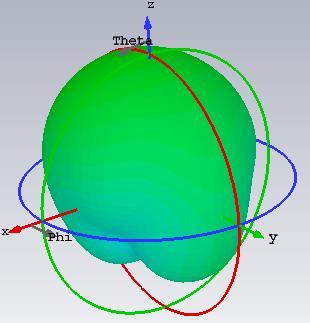


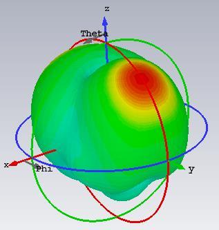
Figure 14: Circular Antenna Far-fields at Different Frequencies.
Table 3: Performance at Different Frequencies of Circular Antenna.
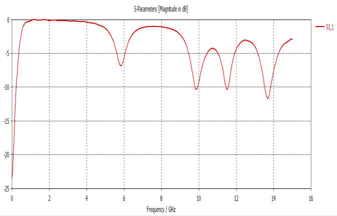
Figure 15: S-parameter of Circular Antenna.

Figure 16: VSWR of Circular Antenna.
International Research Journal of Engineering and Technology (IRJET) e-ISSN:2395-0056
Volume: 11 Issue: 06 | June 2024 www.irjet.net p-ISSN:2395-0072
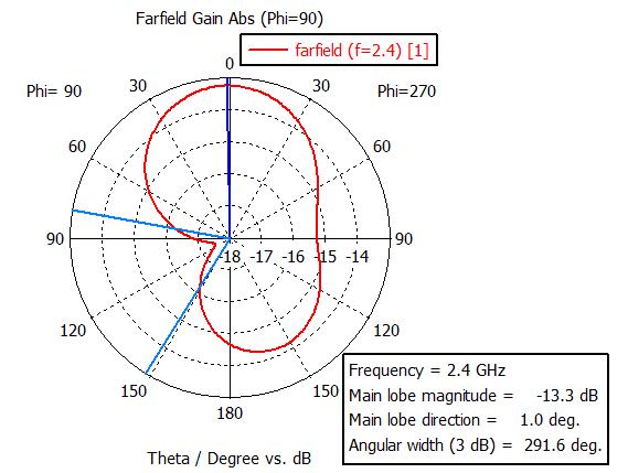
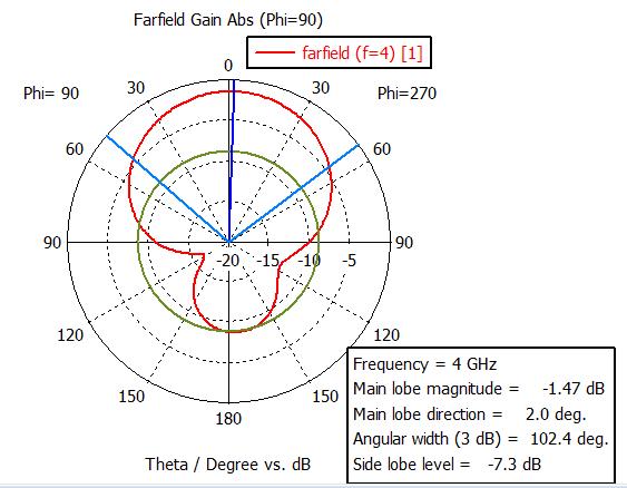
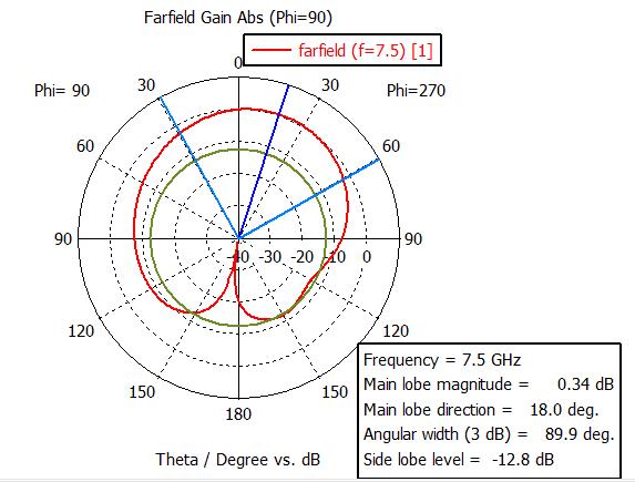
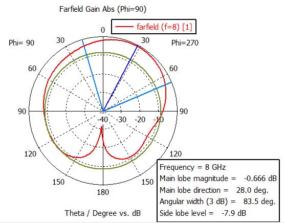
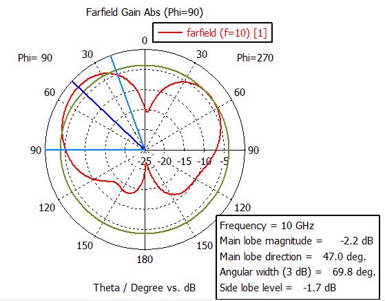

Figure 17: Polar Plot of Circular Antenna.
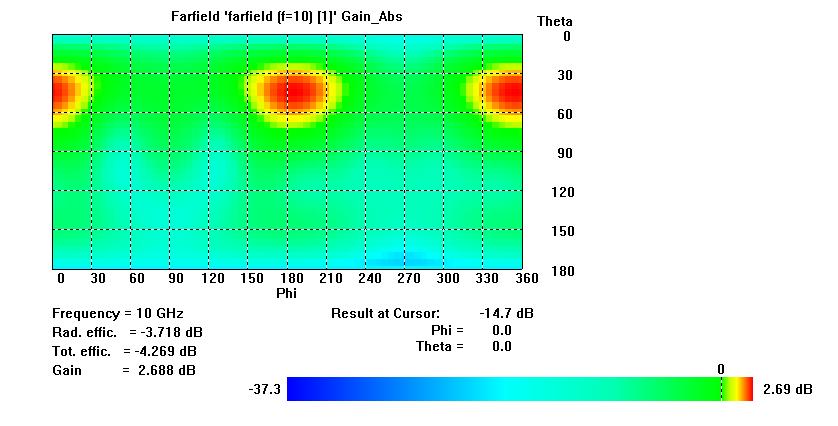
Figure 18: 2D Plot of Circular Antenna.
Dipole antenna:
Thedipoleantenna knownasa doublet[22],isa common formofantennainradioandtelecommunications[23][24]. It is a spreading arrangement with a single node at each end and a path of current, producing radiation patterns
International Research Journal of Engineering and Technology (IRJET) e-ISSN:2395-0056
Volume: 11 Issue: 06 | Jun 2024 www.irjet.net p-ISSN:2395-0072
like those of a basic electric dipole [25].The transmitter sends current to the antenna, which is made up of two similar conducting metals [26], like as power cables or metal poles, and the antenna picks it up. An output signal is produced by the antenna's receiver between its parts. Eachwireislinkedtoeverysideofthefeedlineleadingto the transmitter or receiver. A monopole antenna is made outofasinglerodorconductorwithoneendlinkedtothe feedline[27][28].Themostfrequentkindisthecenter-fed half-wave dipole, which is a little less than half a wavelength When a half-wave polarity is positioned vertically,itproducesanomnidirectionalantenna;whenit ispositionedhorizontally,itproducesaweaklydirectional antenna.Theradiationdistributionofahalf-wavedipoleis highest perpendicular to the conductor and zero in the axialdirection.[29][30].
Application:
Dipole antennas are used in many applications, both as antennas and as components of larger complex antennas where they may act as the dominant radiating element. Theyareemployedinseveralradiosystems,suchasthose fortransmissionacceptance,commonradioreception,and two-wayradiocommunication,alongandnumerous other uses.
Antenna advantage:
They're both inexpensive and profitable. The benefit of using dipole antennas is that they can receive balanced transmissions. The device's two-pole configuration allows it to receive signals over a wide frequency range. It also aids the device in resolving signal conflicts while maintainingoptimalreceptionquality.
Antenna Design:
Aparameterlistisgivenbelow.
Name Expression value description
R 2.5 2.5 Radiusofwire gap 20 20 The gap between twowire
Zo 50
Figure 19: Parameter list of dipole antenna.
How to design the Dipole antenna is given below step by step.
Step1:OpenCSTmicrowavestudio.
Step 2: Select new project then mw/RF and Optical then select antennas then select wire antenna then select time domain.
Step 3: Select minimum and maximum frequency ranges and give a working frequency list then select all monitors likeE-field,H-field,far-field,etc.
Step 4: Select modeling then select bond wire then press ESCandgivethevalueasgivenup.
Outerradius:Rinnerradius:0
X-center:0 Y-center:0.
Z-min:-L/2 Z-max:L/2.
Material:Annulledcopper. Forsubstrate:
Outerradius:RInnerradius:0.
Z-min:-gap/2Z-max:gap/2.
Material:copperannealed.
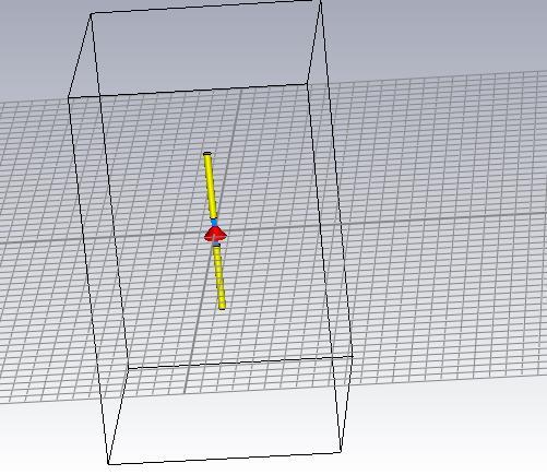
Figure 20: Dipole Antenna.
Simulation output: Antenna simulation steps are given below.
Step1:Calculatewaveguideportsbymacrosfunction.
Step 2: Select simulation then select pick face of feed line thenselectwaveguideportoptionandgivethevaluefrom thecalculation.
Step 3: Select simulation then select setup solver and set accuracy -40dB, normalized to fixed Impedance 50ohm thenpressstart.
Step 4: After completing the simulation double click farfields and select the frequency which far-field want to show.
Step 5: Make a performance table at different frequencies which includes operating frequency, total efficiency, radiationefficiency,gain,anddirectivity.
Step6:ToshowS-parameterdoubleclick1-Dresultsthen select S-parameter and to show bandwidth add curve markerat-10dbpoints.
Step 7: To show VSWR double-click 1-D results and select VSWRoption.
Step 8: To show the polar plot double click far-fields and selectpolarform.
Step 9: To show a 2-D plot double click Far-fields and select2D.

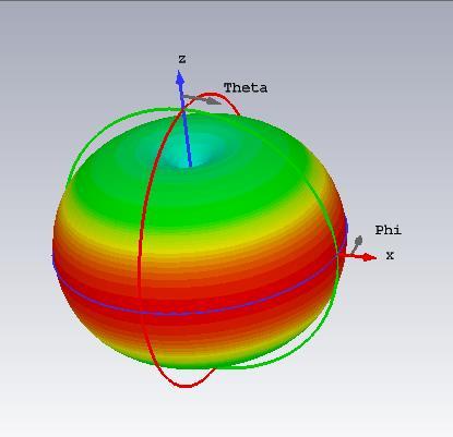
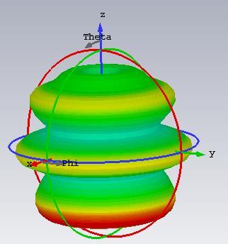
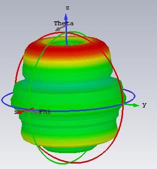


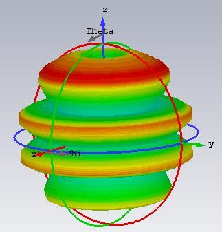

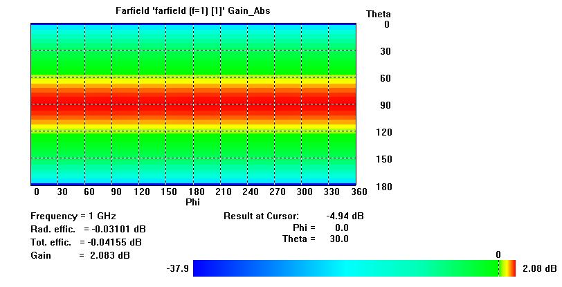
Figure 21: Far-fields at Different Frequencies of Dipole Antenna.
Table 4: Performance Analysis at Different Frequencies of Dipole Antenna.
International Research Journal of Engineering and Technology (IRJET) e-ISSN:2395-0056
Volume: 11 Issue: 06 | Jun 2024 www.irjet.net p-ISSN:2395-0072
S-parameter:

Figure 22: S-parameter of Dipole Antenna.
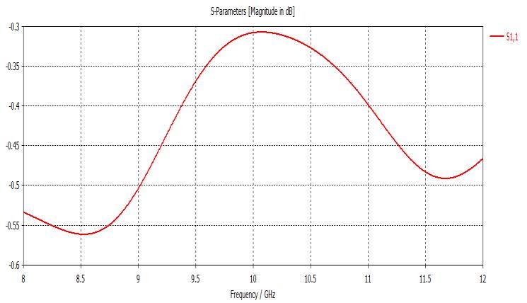
Figure 23: S-parameter at 8-12 GHz.
VSWR:

Figure 24: VSWR Graph of Dipole Antenna.
International
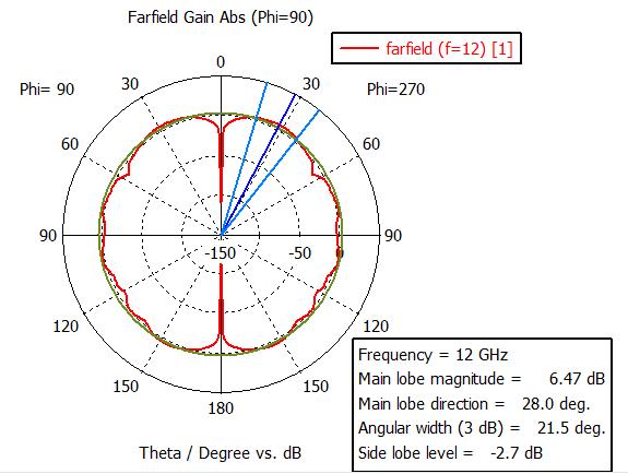

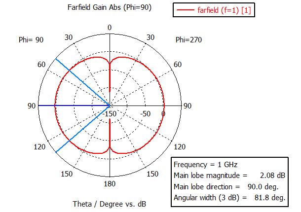
Figure 25: Polar Plot at Different Frequencies of Dipole Antenna.
to link separate antennas to a single transmitter or receiver. Each antenna emits radio waves that combine andsuperposetoincreasetheintensityoftheradiation in targeted directions while blocking out the radiation in other regions. When the receiver is utilized for receiving, the distinct radio frequency currents from each of the various antennas combine in the right phase relationship to amplify signals from desired directions while attenuating signals from undesirable ones. Compared to a singleelement,amulti-elementantennaarraycanprovide alesswidebeamofelectromagneticradiation,bettergain, or both. Generally speaking, the narrower the beam and the higher the gain, the more separate antenna components that are employed. There are some antenna arraysmadeupofthousandsofseparateantennas.Among the many functions of arrays are gain enhancement, route diversity (MIMO) [31], enhanced communication dependability,directiondetermination,electronicsteering oftheradiobeaminvariousdirections,andcancellationof interferencefromcertaindirections.[32].
Advantages:
•Thesignalstrengthgrowsstronger.
•Highdirectivitycanbeachieved.
•Theminorlobesaresignificantlyreduced.
•Thereisahighsignal-to-noiseratio.
•Thereisasignificantgain.
•Thereislesspowerwaste.
•Betterresultsareobtained.
26:
Array Antenna
An antenna array is a collection of linked antennas that functions as a single antenna for both radio wave transmission and reception. Typically, feed lines are used
communications, communications, communications, research is an example of array antenna sorts of elements in an array can be theirradiationpatterns.
ntenna: TheRayleighcriterionstates that the angular breadth of the radio waves produced by an antenna, or its directivity, corresponds to the wavelengthofthewavesdividedbytheantenna'swidth.A directionalantennathatbeamsradiosignalsinarestricted direction can be constructed using one of two general approaches. One way to alter the direction of radio waves is by using large metal surfaces like horns or conical mirrors to reflect them or by using dielectric optics to redirect them. utilizing a single low-gain antenna, into a beam. This form of antenna is called an aperture antenna. Parabolicdishesareanexampleofthistypeofantenna.
Anarray antenna,known as anantenna array,is a second method in which more antennas are joined by the same
Figure
2-D Plot of Dipole Antenna.
International Research Journal of Engineering and Technology (IRJET) e-ISSN:2395-0056
Volume: 11 Issue: 06 | Jun 2024 www.irjet.net p-ISSN:2395-0072
transmitter or receiver. Due to the phenomena of interference, if the inputs are supplied to the antennas in the correct phase, the sphere waves from each individual antenna combine in front of the array to generate plane waves, a beam of electromagnetic radiation going in a particular direction. The power emitted increases as the waves from the several antennas combine when they arriveinphase.
Design: How to design the array antenna is given below stepbystep.
Step1:OpenCSTmicrowavestudio.
Step2: Selecta new project then mw/RF and Optical then select antennas then select planar (patch, slot) then select timedomain.
Step 3: Select a minimum and maximum frequency range and give a working frequency list then select all monitors likeE-field,H-field,far-field,etc.
Step 4: Select modeling then select brick then press ESC andgivethevalueasgivenbelow.
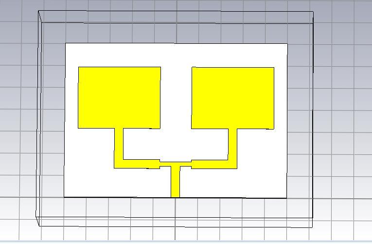
Herewedesignarectangulararrayantenna.Previouslywe designed rectangular and T-shape antennae, same as designed two rectangular antennae upper side of the substrate and downside T-shape antenna then by using Boolean add, we can add two antennas which made the arrayantenna.
Simulation Output
Antennasimulationstepsaregivenbelow.
Step1:Calculatewaveguideportsbymacrosfunction.
Step 2: Select the simulation then select pick face of the feed line then select the waveguide port option and give thevaluefromthecalculation.
Step 3: Select the simulation then select setup solver and setaccuracy-40db,normalizedtofixedImpedance50ohm thenpressstart.
Step 4: After completing the simulation double click farfields and select the frequency which far-field want to show.
Step 5: Make a performance table at different frequencies which includes operating frequency, total efficiency, radiationefficiency,gain,anddirectivity.
Step6:ToshowS-parameterdoubleclick1-Dresultsthen select S-parameter and to show bandwidth add curve markerat-10dbpoints.
Step 7: To show VSWR double-click 1-D results and select VSWRoption.
Step 8: To show the polar plot double click far-fields and selectpolarform.
Step 9: To show a 2-D plot double click Far-fields and select2D.
Figure 27: Parameters of Array Antenna.
Figure 28: Array Antenna.
International Research Journal of Engineering and Technology (IRJET) e-ISSN:2395-0056

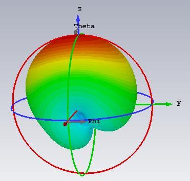
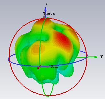
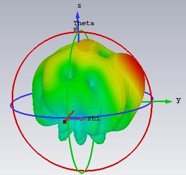

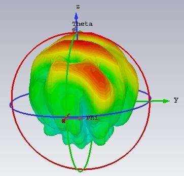
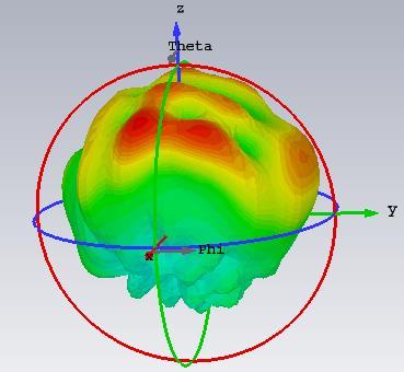
Figure 29: Array Antenna Far-fields at Different Frequencies
Table 5: Performance Analysis of Array Antenna at Different Frequencies.
International Research Journal of Engineering and Technology (IRJET) e-ISSN:2395-0056
Volume: 11 Issue: 06 | Jun 2024 www.irjet.net
S-Parameter:
30: S-parameter at Different Frequencies of Array Antenna.
VSWR:

31: VSWR at Different Frequencies of Array Antenna.
Figure
Figure
PolarPlot:
International Research Journal of Engineering and Technology (IRJET) e-ISSN:2395-0056
Volume: 11 Issue: 06 | Jun 2024 www.irjet.net p-ISSN:2395-0072

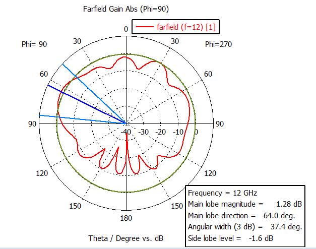
Figure 32: Polar Plot at Different Frequencies of Array Antenna.
2-Dplot:
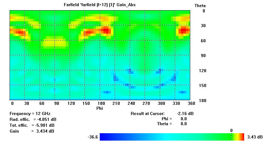
Figure 33: 2D Plot of Array Antenna.
T Shape patch antenna
Transverse capacitive loading wires connected to the top ofamonopoleelectromagneticantennadefineaT-antenna [33].IntheVLF,LF,MF,andshortwavebands,T-antennas are frequently employed as broadcasting antennas for
amateur radio stations as well as long-wave and mediumwave AM radio stations [34][35] [36]. Additionally, they can act as receiving antennas for shortwave listening. The antenna iscomposed ofone or more insulation horizontal wiresthatarehungbetweentworadiomasts orbuildings forreinforcement[33][36].
A vertical wire that passes through the center of the horizontalcablesandswingslowtothegroundisattached to the transmitter or receiver. The name comes from the 'T' shape formed by the two halves. The bottom of the vertical wire and a ground connection are attached to the transmitter or receiver. The T-antenna is a top-loading monopoleantenna.Otherantennasinthiscategoryinclude the inverted L, umbrella, and triangle. Before 1920, it was invented during the early years of radio, during the wirelessera.Itfunctionsasatransmittingantenna.TheTshaped microstrip patch antenna is intended to operate between2and12GHz.
The T-shaped antenna is tiny and flat, with a high gain. Ground structures are used to increase the antenna's bandwidth[37].
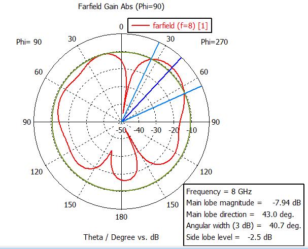
These constructions are created by etching rectangular groovesintothesoil.Circularpolarizedbetween2.5and9 GHzisproducedbyinsertingfourslitsontoasquarepatch with a T-shaped slot; this frequency range is appropriate for WiMAX applications. Compared to earlier designs for circularly polarized antennas, this construction is smaller. Two frequencies are explored for radiation patterns: 2.5GHzand 9GHz. The antenna issimulated using the CST and VSWR. The simulated and observed data were contrastedatthesefrequencies.
Antenna Design:
How to design the T-Shape patch antenna is given below stepbystep.
Step1:OpenCSTmicrowavestudio.
Step2:Selecta new project then mw/RF and Optical then select antennas then select planar (patch, slot) then select timedomain.
Step3:Selecttheminimumandmaximumfrequencyrange and give a working frequency list then select all monitors likeE-field,H-field,far-field,etc.
Step 4: Select modeling then select brick then press ESC andgivethevalueasgivenbelow.
Figure1illustratestheschematicdiagramoftheproposed double T-shape patch antenna. As shown in Figure 1, a waveguide through the silver block is connected with the silicon block for feeding light into the antenna. The geometricparametersareasfollows:
Ground:l=30nm,w=45nm,h=.3nm,
International Research Journal of Engineering and Technology (IRJET) e-ISSN:2395-0056
Volume: 11 Issue: 06 | Jun 2024 www.irjet.net p-ISSN:2395-0072
Substrate:sameasground
Component 1: Uaxix:-l/2 to l/2, Vaxis: 12nm-18nm , Waxis:0.3nm
Component 2: Uaxix: -l/3 to l/3, Vaxis: 4nm-9nm , Waxis: 0.3nm
Component 3: Uaxix: -2.5 to 2.5, Vaxis:-w/2-4nm, Waxis: 0.3nm
Component4: Uaxix: -2.5 to 2.5, Vaxis: 9-12nm, Waxis: 0.3nm
Component5: Uaxix: -l/2 to -3.5, Vaxis: -h/2-3nm , Waxis: 0.3nm
Component6: Uaxix: 3.2 to l/2, Vaxis: -h/2-3nm , Waxis: 0.3nm
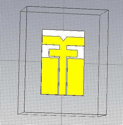
Figure 34: T-shape Antenna
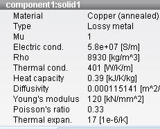
For simulation, a beam of light with TE polarization (xpolarization)isfedintotheT-shapeantennaviathesilicon waveguide. At the frequency of 2.4 GHz, the material propertiesareshowninthebelowfigure.
Simulation Output
Antennasimulationstepsaregivenbelow.
Step1:Calculatewaveguideportsbymacrosfunction.
Step2:Selectthesimulationselectthepickfaceofthefeed line then select the waveguide port option and give the valuefromthecalculation.
Step 3: Select simulation then select setup solver and set accuracy -40db, normalized to fixed Impedance 50ohm thenpressstart.
Step 4: After completing the simulation double click farfields and select the frequency which far-fields want to show.
Step 5: Make a performance table at different frequencies which includes operating frequency, total efficiency, radiationefficiency,gain,anddirectivity.
Step6:ToshowS-parameterdoubleclick1-Dresultsthen select S-parameter and to show bandwidth add curve markerat-10dbpoints.
Step 7: To show the VSWR double-click 1-D results and selecttheVSWRoption.
Step 8: To show the polar plot double click far-fields and selectpolarform.
Step 9: To show a 2-D plot double click Far-fields and select2D.

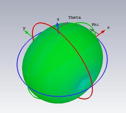

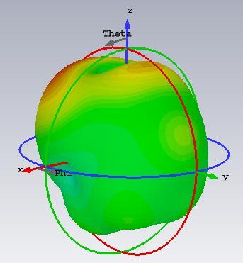
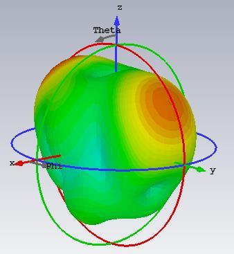
Figure 35: Component Values of T shape.
Volume: 11 Issue: 06 | Jun

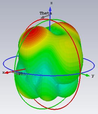

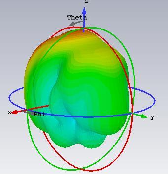
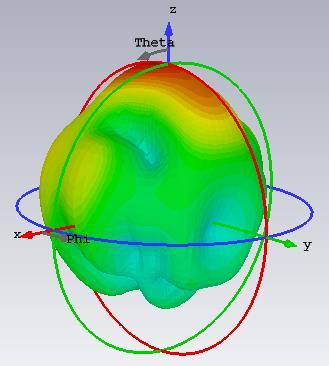
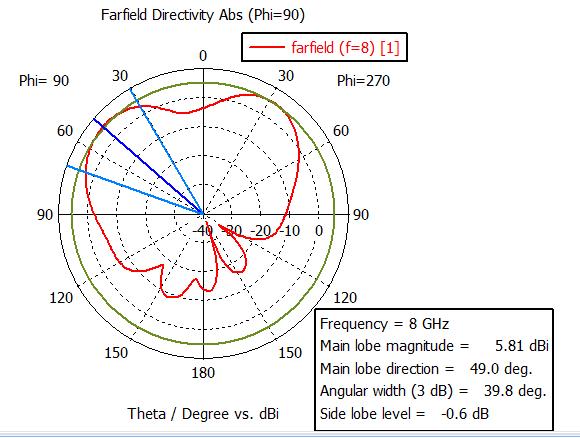
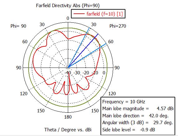
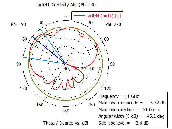
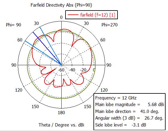
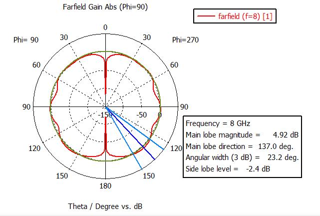
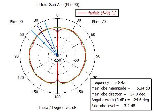
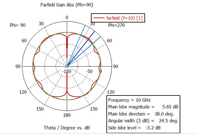
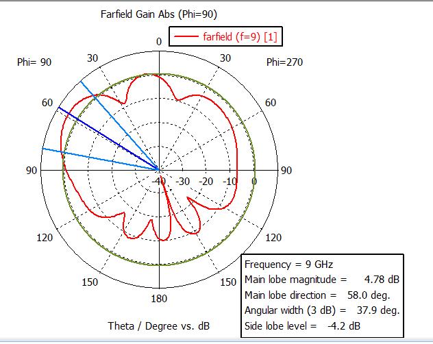
Figure 36: T Shape Antenna Far-fields Radiation Pattern at Different Frequencies
Theperformancetableisgivenbelow.
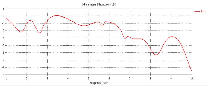
Figure 37: S-parameter of T Shape.
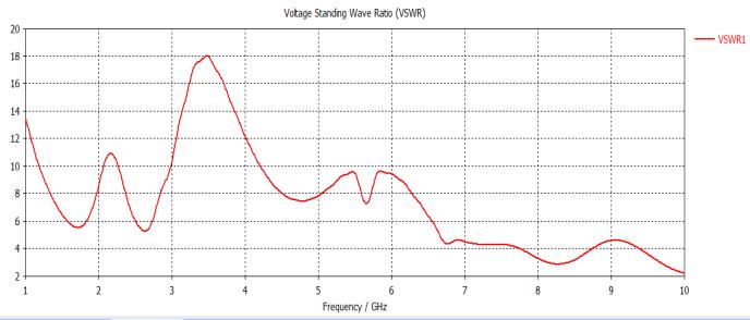
38: VSWR of T Shape.
Polarplot:
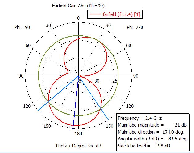
Table 6: T Shape Output Performance Analysis at Different Frequencies.
Figure
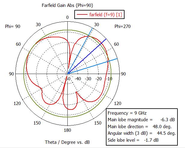
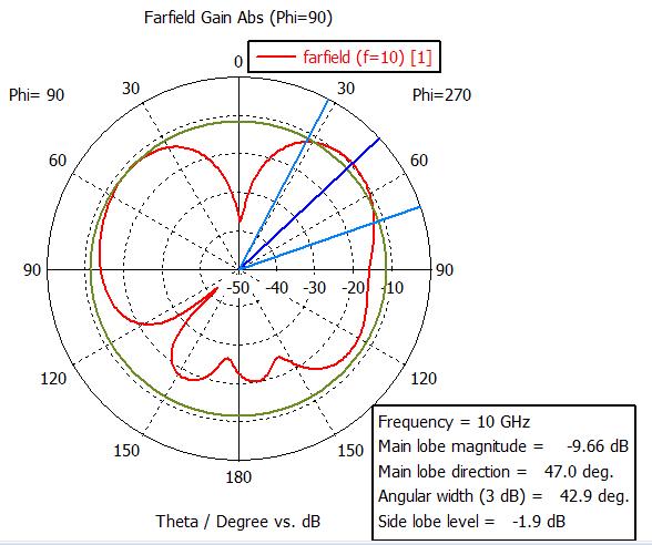
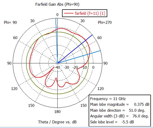
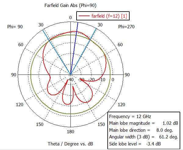
Figure 39: Polar Plot at Different Frequencies of T shape.
6. Expected Outcomes and Contribution of the Research
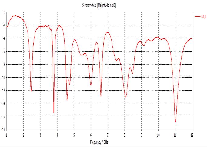
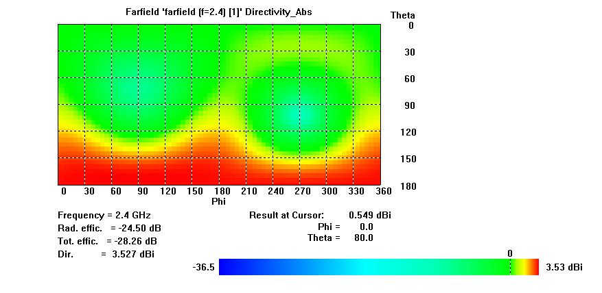
The software has been implemented. We have used CST microwave tools software to implement this proposed model and achieve good results. Our utmost effort has beenmadetoachieveoptimumaccuracy.Inthisstudy,we examined the results of Gain, Directivity, S-parameter, VSWR,polarplot,and2Dplot.TheRectangularmicrostrip patch antenna was the top performer in our analysis. It is suitable for operation at 2.4GHz. At 2.4 GHz, the total efficiencyis-3.90dB,witharadiationefficiencyof-3.33dB, a gain of 4.37dB, and a directivity of 7.71dBi. The frequency directivity at 9GHz, 10GHz, and 11GHz is good, but gain and radiation efficiency are low, as shown in the analysis table. The bandwidth is 2.35-2.42GHz, according to the S-parameter. The circular antenna was the second antenna. It works well at a frequency of 10GHz. Total efficiencyis-4.27dB,radiationefficiencyis-3.72dB,gainis 2.69dB,anddirectivityis6.41dBiatthisfrequency.
Thedipoleantennaisthethirdoption.Thetotalefficiency is -0.41dB, the radiation efficiency is -0.31dB, the gain is 2.08dB,andthedirectivityis2.11dBat1GHz.Thegainand directivity are higher at other frequencies, but the radiation efficiency is much lower. The bandwidth is 0.12GHzaccordingtotheS-parameter.
The array antenna is the fourth. The 2.4GHz frequency is ideal. The total efficiency is -3.91dB, the radiation efficiencyis-3.54dB,thegainis4.70dB,andthedirectivity is 8.24dBi, according to the array antenna performance tableat2.4GHzfrequency. Thedirectivityis12.05dBiand the gain is 6.10dB at 10GHz, yet the radiation efficiency is lower than the overall efficiency. And at 11GHz the gain anddirectivityarealsogood.
Figure 40: 2D Plot of T shape.
International Research Journal of Engineering and Technology (IRJET) e-ISSN:2395-0056
Volume: 11 Issue: 06 | Jun 2024 www.irjet.net
The last one is a microstrip patch antenna with a double T.The system operates effectively at a 12GHz frequency. The overall efficiency at 12 GHz, as indicated in the performance analysis table, is -7.78dB, with a higher radiation efficiency of -7.47dB compared to other frequencies. It has a gain of 1.01dB and a directivity of 8.47dBi,bothofwhichsurpassthoseofotherfrequencies. Each antenna also features polar plots, S-parameters, and 2D plots. The antennas are constructed using FR-4 lossy copper-coated substrate material with a dielectric constant of 4.4 and a thickness of 1.5 mm. The feeding mechanismemployedisamicrostrip50feedline.
7. Future Work
The potential for enhancement is substantial, with the opportunity to extend the component and design to incorporate antennas. Enhancements can involve the utilization of various antenna types, including MIMO antennas, operating at increased frequencies. This advancementwillenablethedetectionoftumorsorcancer cells, such as brain tumors, in the future. Additionally, antennas can be developed for WiFi, WiMAX, and satellite communicationsystems.
8. Conclusion
WefirstthankedAllah,theAlmighty.Completingitwasnot easy. We first learn about CST microwave tools in this section. We learnhow toconstruct antennas andsimulate antennas by using these tools. Antenna is currently a research area in the field of communication. Finally, we completed our work on "Analyzing the performance of several antennas in comparison". Some difficulties with the device's operation were encountered when doing the task. Many software functions and calculations have been incorporated into our work that are commonly used and will aid in efficient analysis. We have put in maximum efforttoensurethehighestlevelofaccuracy.Inthisstudy, we conducted comparisons of Gain, Directivity, Sparameter, VSWR, polar plot, and 2D plot. Five types of antennas are discussed in this paper: the Rectangular microstrip patch antenna, circular patch antenna, dipole antenna, array antenna, and double T shape microstrip patch antenna. The rectangular antenna operates at 2.4GHz, the circular antenna at 10GHz, the Dipole at 10GHz, the Array antenna at 2.4GHz, and the double T shape antenna at 12GHz. There will be numerous opportunitiesforfutureworkonantennas.
9. References:
[1] V. Thakur and S. Kashyap, “A Review Paper on Techniques and Design for Microstrip Patch Antenna”, Int. J. Adv. Res. Electr. Electron. Instrum. Eng., vol. 4, no. 2, pp. 656–662, 2015.
[2] S.Bisht,S.Saini,V.Prakash,andB.Nautiyal,“Study the Various Feeding Techniques of Microstrip Antenna Using Design and Simulation Using CST Microwave Studio”, Int. J. Emerg. Technol. Adv. Eng., vol. 4, no. 9, pp. 318–324, 2014.
[3] T.Ferdous,A.Nayna,andF.Ahmed,“Comparative Study of Rectangular and Circular Microstrip Patch Antennas in X Band”, Int. Conf. Electr. Eng., Inf. Commun. Technol., 2014.
[4] P Mane, S. A. Patil, and P. C. Dhanawade, “Comparative Study of Microstrip Antenna for Different Substrate Material at Different Frequencies”, Int. J. Emerg. Eng. Res. Technol., vol. 2, no. 9, pp. 18–23, 2014.
[5] I. Singh and V. S. Tripathi, “Microstrip Patch Antenna and its Applications” Indrasen Singh al., Int. J. Comp. Tech. Appl., vol. 2, no. 5, pp. 1595–1599, 2011.
[6] S. Tilekar, “Comparative Study of Rectangular, Square, Circular, and Meander Patch Microstrip Antenna,” Int. J. Electr. Electron. Data Commun,no.1,pp.106–109,2015.
[7] J. A. Navarro, K. Chang, J. Tolleson, S. Sanzgiri, T. Instruments, “Design for a Circular Patch Antenna Fed by an Aperture Coupled Microstrip Line. To Improve The Performance, a Cavity Surrounds the Patch to Reduce the Surface Wave Interactions in an Array Environment and Improve Heat Dissipation for Active Devices”, Antennas Propag. Soc. Symp. 1991 Dig. London, Ontario, Canada, vol. 2, pp. 1094–1097, 1991.
[8] S. Shrivastava and A. Bhargava, “A Comparative Study of Different Shaped Patch Antennas with and Without Slots”, Int. J. Eng. Dev. Res., vol. 2, no. 3, pp. 3306–3312, 2014.
[9] R. Khan, T. Jamal, M. I. Aslam, I. Ahmed, and E. Technologies, “Comparative Analysis of
International Research Journal of Engineering and Technology (IRJET) e-ISSN:2395-0056
Volume: 11 Issue: 06 | Jun 2024 www.irjet.net p-ISSN:2395-0072
Different Patch Antennas”, 1st International Electr. Eng. Congr, no. IEEC, 2016.
[10] A. Khidre, S. Member, K. Lee, F. Yang, S. Member, and A. Z. Elsherbeni, “Circular Polarization Reconfigurable Wideband E - Shaped Patch Antenna for Wireless Applications”, IEEE Trans. Antennas Propag., no. c, pp. 1–5, 2011
[11] Tao Dong, Yue Xu, and Jingwen He “Plasmonic Nanoantenna Array Design, Nanoplasmonics’’, Carlos J. Bueno-Alejo, Intech Open, pp.1-5(January 4th, 2020).
[12] W.A.E.Ali,E.K.I.Hamad,M.A.BassiunyandM.Z. M. Hamdalla “Complementary Split Ring Resonator Based Triple Band Microstrip Antenna for WLAN/WiMAX Applications”, 1st International Electr. Eng. Congr, no. IEEC, 2016.
[13] C.ŞekerandM.T.Güneşer,"Design and Simulation of 26 GHz Patch Antenna for 5G Mobile Handset", 11th International Conference on Electrical and Electronics Engineering (ELECO), 2019, pp. 676-678, doi: 10.23919/ELECO47770.2019.8990634.
[14] H.G.AkhavanandD.M.Syahkal,“Study of Coupled Slot Antennas Fed by Microstrip Lines”, 10th International Conference on Antennas and Propagation, Edinburgh, UK, vol. 1, pp. 1290–1292, 1997.
[15] R. Vaughan and J. B. Anderson, Channels, “Propagation and Antennas for Mobile Communications”, IEEE, London, 2003.
[16] Tansarıkaya, “Geniş Bandlı Yama Antenna Tasarımı (Doctoral dissertation”, Fen Bilimleri Enstitüsü 2007.
[17] Wa'il, A., Shaaban, R. M., & Duffy, A. P. “Design, Simulation, and Fabrication of a Double annular Ring Microstrip Antenna Based on Gaps with Multiband Feature”, Engineering Science and Technology, an International Journal 2021.
[18] Acıkaya, F. C., & Yıldırım, B. S, “A Dual-Band Microstrip Patch Antenna for 2.45/5-GHz WLAN Applications”, AEU-International Journal
of Electronics and Communications, 2021,p. 141, 153957.
[19] Wa'il, A., Shaaban, R. M., & Tahir, A., “Design, Simulation and Measurement of Triple Band Annular ring Microstrip Antenna Based on Shape of Crescent Moon”, AEU-International Journal of Electronics and Communications, 2021,p.117, 153133
[20] Shera Prabjyot Singh, Ashish Singh, Deepak Upadhyay, Sunilkumar Pal, Mahesh Munde, “Design and Fabrication of Microstrip Patch Antenna at 2.4 GHz for WLAN Application using HFSS”, IOSR Journal of Electronics and Communication Engineering (IOSR-JECE) Special issue AETM’16 Volume No. 1
[21] B.Sai Sandeep; S.Sreenath Kashyap, “Design and Simulation of Microstrip Patch Array antenna for Wireless Communication at 2.4 GHz”, International Journal of Scientific & Engineering Research, Volume 3, Issue 11, November 2012.
[22] Winder, Steve; Carr, Joseph, “Newnes Radio and RF Engineering Pocket Book” (3rd ed.2002). Newnes. p. 4. ISBN 0080497470
[23] Acıkaya, F. C., & Yıldırım, B. S, “A Dual-Band Microstrip Patch Antenna for 2.45/5-GHz WLAN applications”, AEU-International Journal of Electronics and Communications,2002,p. 141, 153957.
[24] Basu, Dipak, “Dictionary of Pure and Applied Physics (2nd ed.)”,CRC Press. 2010, p. 21. ISBN 978-1420050226.
[25] Bodnar, Donald, ANSI/IEEE Std 145-1993 IEEE “Standard Definitions of Terms for Antennas”, New York, NY: The Institute of Electrical and Electronics Engineers, Inc.1993, pp. 10,2,102
[26] "Dipole Antenna / Aerial tutorial", Resources. Radio-Electronics.com. Adrio Communications, Ltd. 2011.Retrieved29April2013.
[27] Rouse, Margaret, "Dipole Antenna". Online IT Encyclopedia. whatis.techtarget.com Retrieved 29 April2013.
[28] Balanis, Constantine A, “Modern Antenna Handbook. John Wiley & Sons”. p. 2.3. ISBN 9781118209752
International Research Journal of Engineering and Technology (IRJET) e-ISSN:2395-0056
Volume: 11 Issue: 06 | Jun 2024 www.irjet.net p-ISSN:2395-0072
[29] Balanis, Constantine A. (2011),“ Modern Antenna Handbook. John Wiley and Sons”, pp. 2–1. ISBN 978-1118209752.
[30] Stutzman, Warren L.; Thiele, Gary A., “Antenna Theory and Design”, John Wiley and Sons, 2012 pp. 74–75. ISBN 978-0470576649.
[31] Poole, Ian, "What is MIMO? Multiple Input Multiple Output Tutorial", Antennas and propagation. Radio-electronics Communications RetrievedFebruary23,2017.
[32] Bevelacqua, Peter, "Array Antennas", Antennatheory.com RetrievedFebruary23,2017
[33] Graf,RudolfF,“Modern Dictionary of Electronics”, 7th Ed. USA: Newnes. 1999 p. 761. ISBN 0-75069866-7
[34] Chatterjee, Rajeswari, “Antenna Theory and Practice, 2nd Ed”. New Delhi: New Age International, 2006 pp. 243–244. ISBN 81-2240881-8
[35] Rudge,AlanW,“The Handbook of Antenna Design”, Vol. 2. IET. 19983 pp. 554, 578–579. ISBN 0906048-87-7
[36] Edwards, R.J. G4FGQ, “The Simple Tee Antenna”, Antenna design library Retrieved 23 February 2012
[37] Straw, R. Dean, “The ARRL Antenna Book (19th ed.)” USA: American Radio Relay League. 2006 pp 6-36. ISBN 0-87259-817-9